BP480V09 - Power bank Tripp Lite - Free user manual and instructions
Find the device manual for free BP480V09 Tripp Lite in PDF.
User questions about BP480V09 Tripp Lite
0 question about this device. Answer the ones you know or ask your own.
Ask a new question about this device
Download the instructions for your Power bank in PDF format for free! Find your manual BP480V09 - Tripp Lite and take your electronic device back in hand. On this page are published all the documents necessary for the use of your device. BP480V09 by Tripp Lite.
USER MANUAL BP480V09 Tripp Lite
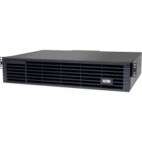
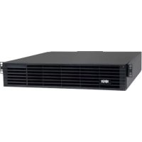
External Battery Pack
for Use with 3-Phase Online S3MX Series (S3M30KX/40KX)
Models: BP480V09, BP480V10, BP480V10-NIB
natural_image
Line drawing of a rectangular industrial machine with wheels and a side panel (no text or symbols)- Important Safety Warnings 2
- Installation and Setup 3
2.1 Rear Panel View 3
2.2 Battery Pack Installation and Setup 3
2.3 Installing Batteries in an External Battery Pack Cabinet 6
-
Specifications 8
-
Storage and Service 9
- Warranty 9
Español 10
Français 19
Русский 28
Deutsch
37

text_image
TRIPP·LITE
Manufacturing
Excellence.
1111 W. 35th Street, Chicago, IL 60609 USA • www.tripplite.com/support
Copyright © 2018 Tripp Lite. All rights reserved.
1. Important Safety Warnings

SAVE THESE INSTRUCTIONS
All sections of this manual contain instructions and warnings that must be followed during the installation and operation of the battery cabinet described in this manual. Read ALL instructions thoroughly before attempting to move, install or connect your battery cabinet. Failure to heed these warnings may affect your warranty and cause serious property damage and/or personal injury.

DANGER! LETHAL HIGH VOLTAGE HAZARD!
All wiring should be performed by a qualified electrician, in accordance with the warnings in this manual and all applicable electrical and safety codes. Incorrect wiring may cause serious personal injury and property damage.
Installation and Location Warnings
• Install the battery cabinet in a controlled indoor environment, away from moisture, temperature extremes, flammable liquids and gasses, conductive contaminants, dust and direct sunlight.
• Install the battery cabinet in a level, structurally sound location.
- The battery cabinet is very heavy; use extreme caution when moving or lifting the unit.
- Operate the battery cabinet at indoor temperatures between 0^ and 40^ (32°F and 104°F) and 30-90% non-condensing humidity only. For optimum battery performance, maintain an ambient indoor temperature of 25^ (77°F).
- Leave adequate space around the front and rear of the battery cabinet for proper ventilation. Do not block, cover or insert objects into the external ventilation openings of the battery cabinet.
- Do not place any object on the battery cabinet, especially containers of liquid.
- Do not attempt to stack the battery cabinet. Attempting to stack the battery cabinet may cause permanent damage and create a potential for serious personal injury.
- Do not attempt to unpack or move the battery cabinet without assistance. Use appropriate handling equipment rated to bear the weight and bulk of the battery cabinet, such as freight elevators, pallet jacks and forklifts. (Fully extend forks under load. Spread forks to maximum possible width under load. Lift cabinet from bottom only. Wear safety shoes.)
- For emergency use, install a fire extinguisher rated for energized electrical equipment fires (Class C rating or exact equivalent, with a non-conductive extinguishing agent) near the battery cabinet.
Connection Warnings
- The battery cabinet contains hazardous high voltages that have the potential to cause personal injury or death from electric shock.
- The battery cabinet has its own energy source. The output terminals may be live even when the battery cabinet is not connected to a UPS system.
- The battery cabinet must be suitably grounded according to all applicable electrical wiring regulations.
- Use of this equipment in life support applications where failure of this equipment can reasonably be expected to cause the failure of the life support equipment or to significantly affect its safety or effectiveness is not recommended.
- De-energize all input and output power sources before installing cables or making electrical connections.
- Use flexible cable of sufficient length to permit battery cabinet servicing.
- Use ferrule caps to cover termination cables and prevent frayed ends from shorting on terminal blocks. Use cabling rated VW-1, FT-1 or better. Use cable sleeves and connector clamps.
- Confirm that all cables are marked correctly according to their purpose, polarity and diameter.
- Observe proper polarity by connecting negative to negative and positive to positive (and center string to center string, where applicable). Failure to observe proper polarity may damage the batteries and create a serious risk of personal injury and property damage.
- Wiring should be performed by trained, qualified electricians only. Refer to the UPS unit's Owner's Manual for wire sizing.
Battery Warnings
- The battery cabinet does not require routine maintenance by the user. There are no user-serviceable parts inside. Only qualified, knowledgeable service personnel familiar with all required precautions should open the access panels for any reason. Keep unauthorized personnel away from batteries.
- The battery cabinet contains valve-regulated recombinant lead-acid (VRLA) batteries. Do not attempt to add water to these batteries or sample the electrolyte specific gravity.
- Valve-regulated recombinant lead-acid (VRLA) batteries can contain an explosive mixture of hydrogen gas. DO NOT SMOKE when near batteries. DO NOT cause flames or sparks near batteries. Discharge static electricity from body before touching batteries. DO NOT open or mutilate batteries—released electrolyte is harmful to the skin and eyes and may be toxic. DO NOT dispose of batteries in a fire—they may explode.
1. Important Safety Warnings

- Batteries present a risk of electrical shock and burns from high short-circuit current. Battery connection or replacement should be performed only by qualified service personnel, observing proper precautions. Use tools with insulated handles. Remove watches, rings or other metal objects. Wear rubber gloves and boots. Do not short or bridge the battery terminals with any object. Do not lay tools or metal parts on top of batteries. Use tools with insulated handles. There are no user-serviceable parts inside the battery cabinet. Battery replacement should be performed only by authorized service personnel using the same number and type of batteries (sealed lead-acid). The batteries are recyclable. Refer to your local codes for disposal requirements or visit http://www.tripplite.com/support/recycling-program for recycling information. Tripp Lite offers a complete line of UPS System Replacement Battery Cartridges (R.B.C.). Visit Tripp Lite on the Web at https://www.tripplite.com/products/battery-finder/ to locate the specific replacement battery for your UPS.
- Replace batteries with equivalent batteries (same number and type) available from Tripp Lite.
- Fuse replacement should only be performed by qualified service personnel. Replace with only the same type and rating: 30A, 600V.
- The batteries are recyclable. Refer to local codes for disposal requirements. Do not dispose of batteries except through approved channels in accordance with all applicable local, state and national regulations.
- Do not connect or disconnect batteries when the UPS system is operating from the battery supply or when the unit is not in bypass mode. Disconnect the charging source prior to connection or disconnecting battery terminals.
- If the charging source remains off for an extended period of time, it should be turned on periodically to allow the batteries to recharge. The charging source should be turned on and the batteries should be recharged at least one uninterrupted 24-hour period every 3 months. Failure to recharge the batteries periodically may cause permanent battery damage.
- Allow batteries to charge uninterrupted for 24 hours after installation.
2. Installation and Setup
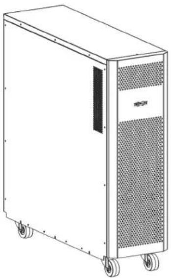
2.1 Rear Panel View
Note: Inspect the unit before performing installation. Make sure nothing inside the package is damaged. Keep the original packaging for future use.
1 DC Connector: Connects to UPS or a second battery pack. For more information, see Connecting a UPS to the Battery Pack in section 2.2 Battery Pack Installation and Setup.
② Fuse Holder: Battery over-current protection fuse holder.
2.2 Battery Pack Installation and Setup
Unpacking and Inspection
- Remove the battery pack from the packaging.
Note: The battery pack is very heavy. Be cautious when unpacking and lifting the unit to avoid injury.
-
Inspect the package contents for impact or other damage:
-
Battery Pack Unit
- Owner's Manual
- Battery Connection Cable
text_image
Second Battery Pack (Optional) UPS 1 280-pc. Battery Pack
2. Installation and Setup
Selecting Installation Site
To minimize the possibility of damage to the battery bank and extend the life of the batteries, follow the instructions below:
- Maintain at least 20 cm (8 inches) clearance between the unit's rear panel and a wall (or other obstructions).
- Do not block airflow to the unit's ventilation openings.
- Ensure the installation site environmental conditions are in accordance with the unit's working specifications to avoid overheating and/or excessive moisture.
- Do not place the unit in a dusty or corrosive environment or near any flammable objects.
- This unit is not designed for outdoor use.
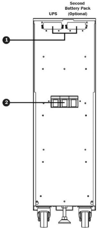
Connecting a UPS to the Battery Pack
The external battery pack will increase the battery runtime. As a result, recharge time will also increase. The diagram below shows a UPS connected to a battery pack using the included cable, and the battery pack connected to an optional second battery pack.

Before attempting to connect the battery pack to a UPS, please follow the Removing Battery Connector Cover and Installing Battery Cable Bracket procedure.
text_image
Technical diagram showing front and rear views of a server rack with fan and drive unit, annotated with red and blue circles indicating connection points.2. Installation and Setup
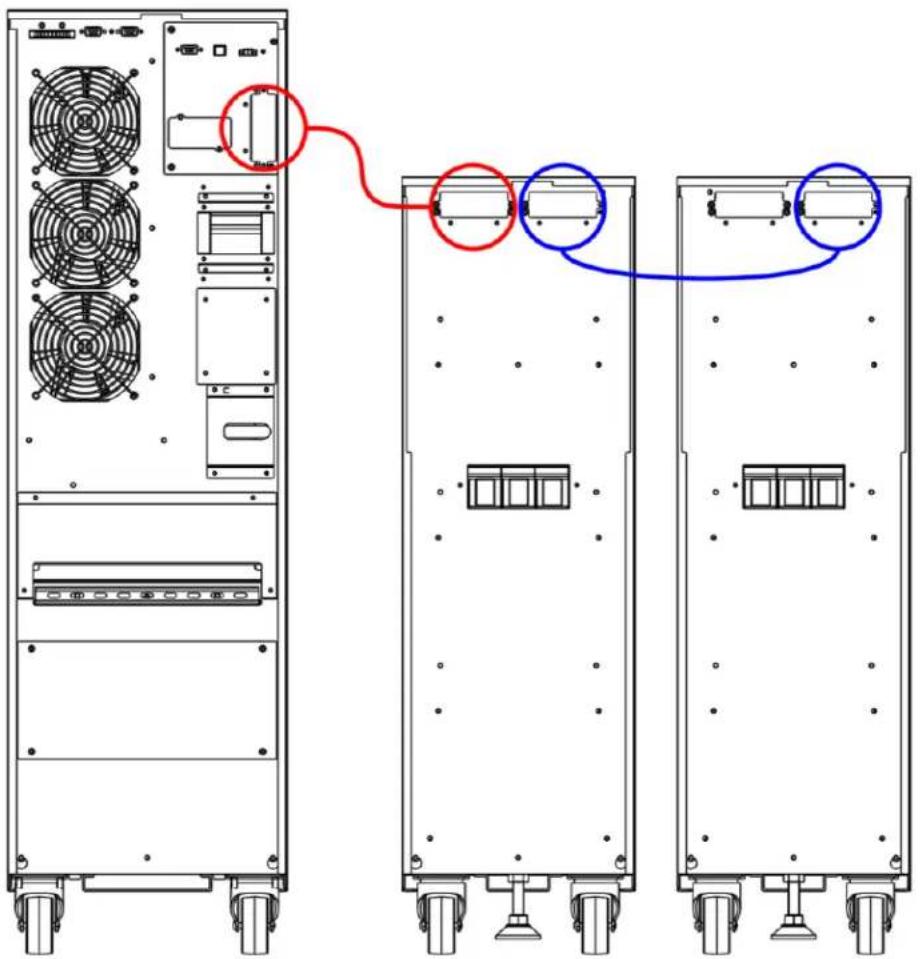
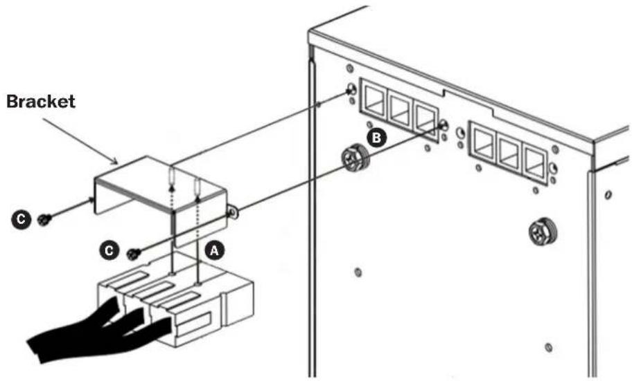
Removing Battery Connector Cover and Installing Battery Cable Bracket
- Unscrew the screws securing the cover of the battery pack's UPS DC connector. Remove cover and save screws for step 4.
Note: The UPS DC connector is located on the left side.
-
Attach the cable bracket to the battery cable A.
-
Connect the external battery connector to battery pack B.
Notes:
• Make sure the cable is fully inserted into their connectors.
- Small sparks may result during battery connection; this is normal.
- Be sure to connect the protective earth wire ring terminals to the earth bonding screw on each cabinet.
- Use the two screws removed in step 2 to secure the battery cable to the battery pack cabinet ⓒ.
text_image
Bracket C A B2. Installation and Setup
2.3 Installing Batteries in an External Battery Pack Cabinet

If your external battery pack cabinet does not include batteries installed, follow the proper procedures to install batteries inside the unit.
MAKE SURE THE BATTERY PACK CABINET IS DISCONNECTED FROM THE UPS BEFORE PERFORMING THE FOLLOWING SEQUENCE OF OPERATIONS.
WARNING:
• Equipment should be installed by service personnel.
- When installing the batteries, use the same battery number and type as shown on the battery label.
- Do not open or mutilate the battery or batteries. The released electrolyte is harmful to the skin and eyes.
- A battery can present a risk of electric shock and high short-circuit current. Observe the following precautions when working on batteries:
o Remove watches, rings or other metal objects.
o Use tools with insulated handles.
Install Batteries in an External Battery Pack Cabinet:
Note: Refer to the External Battery Pack Wiring Diagram and External Battery Pack Cabinet Battery Wiring Table for more information.
- Remove the two side plates and four barrier plates.
- Install 80 batteries into the battery pack.
- Route the cables through the opening behind the battery breaker. DO NOT route cables through or around the shelves.
- Reinstall the four barrier plates to secure all batteries.

When installing the barrier plates, do not short circuit the battery terminals. Injury or fire may result.
- Connect the two red wires, two black wires and four blue wires from the fuse holder to the batteries.
- Connect four 320 mm wires.
- Connect 72 100 mm wires.
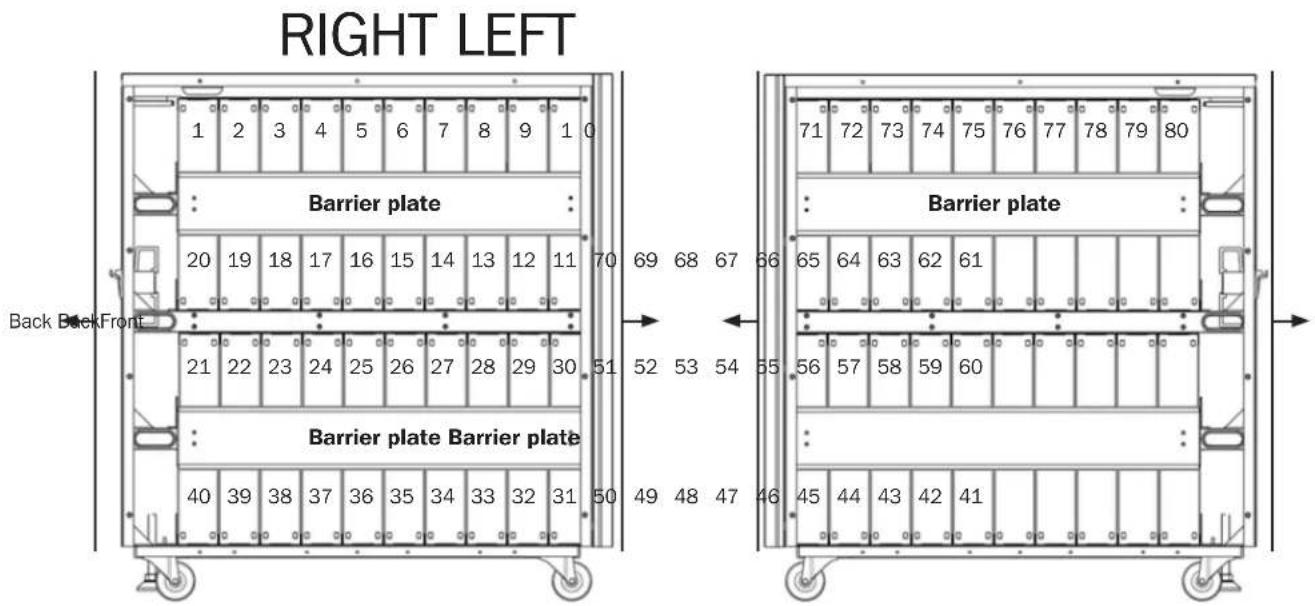
External Battery Pack Wiring Diagram
text_image
RIGHT LEFT 1 2 3 4 5 6 7 8 9 1 0 Barrier plate 20 19 18 17 16 15 14 13 12 11 70 69 68 67 66 Back BackFront Barrier plate Barrier plate 40 39 38 37 36 35 34 33 32 31 50 49 48 47 46 Barrier plate 71 72 73 74 75 76 77 78 79 80 Barrier plate 65 64 63 62 61 56 57 58 59 60 45 44 43 42 412. Installation and Setup
Notes:
- The numbers listed in the diagram are "Battery Numbers" from 1 to 80, which are used for battery position identification.
- Connector cables are labeled by polarity and the respective battery number it connects to. For example, the cable labeled "40 (+)" should connect to battery number 40's positive battery terminal. Refer to the battery connection diagram for all connector cable assignments.
The numbers listed in the diagram are "Battery Numbers" from 1 to 80, which are used for battery position identification. - Connector cables are labeled by polarity and the respective battery number it connects to. For example, the cable labeled "40 (+)" should connect to battery number 40's positive battery terminal. Refer to the battery connection diagram for all connector cable assignments.

text_image
DC CONNECTOR EXTERNAL FUSE HOLDER (100A/700V FUSE) FUSE BOARD (30A/600V) FUSE BOARD (30A/600V)FUSE BOARD (30A/600V) 100 mm wire 320 mm wire 320 mm wire Front 320 mm wire 320 mm wire 45 44 43 42 41 80 (+) 61 (N) 60 (N) Back 10 71 72 73 74 75 76 77 78 79 80 70 69 68 67 66 65 64 63 62 61 51 52 53 54 55 56 57 58 59 60 DEExternal Battery Pack Wiring Table
| BAT Number | 1 | 2 | 3 | 4 | 5 | 6 | 7 | 8 | 9 | 10 | ||||||||||
| Terminal | - | + | - | + | - | + | - | + | - | + | - | + | - | + | - | + | - | + | - | + |
| Connection Wire | Black Wire from Fuse Holder | 100 mm Wire | 100 mm Wire | 100 mm Wire | 100 mm Wire | 100 mm Wire | 100 mm Wire | 100 mm Wire | 100 mm Wire | 100 mm Wire | See Below | |||||||||
| BAT Number | 10 | 11 | 12 | 13 | 14 | 15 | 16 | 17 | 18 | 19 | ||||||||||
| Terminal | - | + | - | + | - | + | - | + | - | + | - | + | - | + | - | + | - | + | - | + |
| Connection Wire | 320 mm Wire | 100 mm Wire | 100 mm Wire | 100 mm Wire | 100 mm Wire | 100 mm Wire | 100 mm Wire | 100 mm Wire | 100 mm Wire | See Below | ||||||||||
| BAT Number | 19 | 20 | 21 | 22 | 23 | 24 | 25 | 26 | 27 | 28 | ||||||||||
| Terminal | - | + | - | + | - | + | - | + | - | + | - | + | - | + | - | + | - | + | - | + |
| Connection Wire | 100 mm Wire | Blue Wire from Fuse Holder | Blue Wire from Fuse Holder | 100 mm Wire | 100 mm Wire | 100 mm Wire | 100 mm Wire | 100 mm Wire | 100 mm Wire | 100 mm Wire | See Below | |||||||||
| BAT Number | 28 | 29 | 30 | 31 | 32 | 33 | 34 | 35 | 36 | 37 | ||||||||||
| Terminal | - | + | - | + | - | + | - | + | - | + | - | + | - | + | - | + | - | + | - | + |
| Connection Wire | 100 mm Wire | 100 mm Wire | 320 mm Wire | 100 mm Wire | 100 mm Wire | 100 mm Wire | 100 mm Wire | 100 mm Wire | 100 mm Wire | See Below | ||||||||||
| BAT Number | 37 | 38 | 39 | 40 | ||||
| Terminal | - | + | - | + | - | + | - | + |
| Connection Wire | 100 mm Wire | 100 mm Wire | 100 mm Wire | Red Wire from Fuse Holder | ||||
2. Installation and Setup
| BATNumber 4 | 1 42 43 44 45 46 47 48 49 50 | |||||||||||||||||||
| Terminal | - | + | - | + | - | + | - | + | - | + | - | + | - | + | - | + | - | + | - | + |
| Connection Wire | Black Wire from Fuse Holder | 100 mm Wire | 100 mm Wire | 100 mm Wire | 100 mm Wire | 100 mm Wire | 100 mm Wire | 100 mm Wire | 100 mm Wire | 100 mm Wire | See Below | |||||||||
| BATNumber | 50 51 52 53 54 55 56 57 58 59 | |||||||||||||||||||
| Terminal | - | + | - | + | - | + | - | + | - | + | - | + | - | + | - | + | - | + | - | + |
| Connection Wire | 320 mm Wire | 100 mm Wire | 100 mm Wire | 100 mm Wire | 100 mm Wire | 100 mm Wire | 100 mm Wire | 100 mm Wire | 100 mm Wire | See Below | ||||||||||
| BAT Number | 59 | 60 | 61 | 62 | 63 | 64 | 65 | 66 | 67 | 68 | ||||||||||
| Terminal | - | + | - | + | - | + | - | + | - | + | - | + | - | + | - | + | - | + | - | + |
| Connection Wire | 100 mm Wire | Blue Wire from Fuse Holder | Blue Wire from Fuse Holder | 100 mm Wire | 100 mm Wire | 100 mm Wire | 100 mm Wire | 100 mm Wire | 100 mm Wire | 100 mm Wire | See Below | |||||||||
| BATNumber | 68 69 70 71 72 73 74 75 76 77 | |||||||||||||||||||
| Terminal | - | + | - | + | - | + | - | + | - | + | - | + | - | + | - | + | - | + | - | + |
| Connection Wire | 100 mm Wire | 100 mm Wire | 320 mm Wire | 100 mm Wire | 100 mm Wire | 100 mm Wire | 100 mm Wire | 100 mm Wire | 100 mm Wire | See Below | ||||||||||
| BATNumber | 77 78 79 | 80 | ||||||
| Terminal | - | + | - | + | - | + | - | + |
| Connection Wire | 100 mm Wire | 100 mm Wire | 100 mm Wire | Red Wire from Fuse Holder | ||||
3. Specifications
| Battery Cabinet Model | Included Breakers | Unit Dimensions (H x W x D) | Shipping Dimensions (H x W x D) | Unit Weight | Shipping Weight | Description |
| BP480V09 | kg 290 kg100A Fuses | 836 x 250 x 779 mm 10 | 18.5 x 380 x 919.5 mm | 246.5 kg | 273.5 kg | Battery cabinet with 80 x 9Ah batteries pre-installed. |
| BP480V10 273 kg | Battery cabinet with 80 x 10Ah batteries pre-installed. | |||||
| BP480V10-NIB 55 kg 82 kg | Battery cabinet without batteries installed, but designed for 80 x 10Ah/9Ah batteries. Battery links and fuses included. |
4. Storage and Service
Storage
If the charging source remains off for an extended period of time, it should be turned on periodically to allow the batteries to recharge. The charging source should be turned on and the batteries should be recharged for at least one uninterrupted 24-hour period every 3 months. Failure to recharge the batteries periodically may cause permanent battery damage.
Service
Your Tripp Lite product is covered by the warranty described in this manual. A variety of Extended Warranty and On-Site Service Programs are also available from Tripp Lite. For more information on service, visit www.triplite.com/support. Before returning your product for service, follow these steps:
- Review the installation and operation procedures in this manual to ensure that the service problem does not originate from a misreading of the instructions.
- If the problem continues, do not contact or return the product to the dealer. Instead, visit www.tripplite.com/support.
- If the problem requires service, visit www.triplite.com/support and click the Product Returns link. From here you can request a Returned Material Authorization (RMA) number, which is required for service. This simple on-line form will ask for your unit's model and serial numbers, along with other general purchaser information. The RMA number, along with shipping instructions will be emailed to you. Any damages (direct, indirect, special or consequential) to the product incurred during shipment to Tripp Lite or an authorized Tripp Lite service center are not covered under warranty. Products shipped to Tripp Lite or an authorized Tripp Lite service center must have transportation charges prepaid. Mark the RMA number on the outside of the package. If the product is within its warranty period, enclose a copy of your sales receipt. Return the product for service using an insured carrier to the address given to you when you request the RMA.
5. Warranty
1-YEAR LIMITED WARRANTY
Seller warrants this product, if used in accordance with all applicable instructions, to be free from original defects in material and workmanship for a period of one (1) year from the date of initial purchase. If the product should prove defective in material or workmanship within that period, Seller will repair or replace the product, in its sole discretion. Service under this Warranty can only be obtained by your delivering or shipping the product (with all shipping or delivery charges prepaid) to: Tripp Lite, 1111 W. 35th Street, Chicago, IL 60609 USA. Seller will pay return shipping charges. Visit www.tripplite.com/support before sending any equipment back for repair.
THIS WARRANTY DOES NOT APPLY TO NORMAL WEAR OR TO DAMAGE RESULTING FROM ACCIDENT, MISUSE, ABUSE OR NEGLECT. SELLER MAKES NO EXPRESS WARRANTIES OTHER THAN THE WARRANTY EXPRESSLY SET FORTH HEREIN. EXCEPT TO THE EXTENT PROHIBITED BY APPLICABLE LAW, ALL IMPLIED WARRANTIES, INCLUDING ALL WARRANTIES OF MERCHANTABILITY OR FITNESS, ARE LIMITED IN DURATION TO THE WARRANTY PERIOD SET FORTH ABOVE; AND THIS WARRANTY EXPRESSLY EXCLUDES ALL INCIDENTAL AND CONSEQUENTIAL DAMAGES. (Some states do not allow limitations on how long an implied warranty lasts, and some states do not allow the exclusion or limitation of incidental or consequential damages, so the above limitations or exclusions may not apply to you. This Warranty gives you specific legal rights, and you may have other rights which vary from jurisdiction to jurisdiction).
WARNING: The individual user should take care to determine prior to use whether this device is suitable, adequate or safe for the use intended. Since individual applications are subject to great variation, the manufacturer makes no representation or warranty as to the suitability or fitness of these devices for any specific application.
Regulatory Compliance Identification Numbers
For the purpose of regulatory compliance certifications and identification, your Tripp Lite product has been assigned a unique series number. The series number can be found on the product nameplate label, along with all required approval markings and information. When requesting compliance information for this product, always refer to the series number. The series number should not be confused with the marketing name or model number of the product.
WEEE Compliance Information for Tripp Lite Customers and Recyclers (European Union)

Under the Waste Electrical and Electronic Equipment (WEEE) Directive and implementing regulations, when customers buy new electrical and electronic equipment from Tripp Lite they are entitled to:
- Send old equipment for recycling on a one-for-one, like-for-like basis (this varies depending on the country)
- Send the new equipment back for recycling when this ultimately becomes waste
Tripp Lite has a policy of continuous improvement. Specifications are subject to change without notice.

text_image
TRIPP·LITE
1111 W. 35th Street, Chicago, IL 60609 USA • www.tripplite.com/support
natural_image
Line drawing of a modular electronic device with wheels and a central panel (no text or symbols)1111 W. 35th Street, Chicago, IL 60609 EE UU • www.tripplite.com/support
text_image
Technical diagram showing front and rear views of a server rack with fan, ventilation units, and labeled connectorsnatural_image
Line drawing of a rectangular industrial machine with wheels and a side panel (no text or symbols)text_image
Technical diagram showing front and rear views of a server rack with fan, drive, and ventilation units connected by red and blue wiring.2. Installation et configuration
text_image
Support A B C C2. Installation et configuration
GARANTIE LIMITÉE D'UN AN
1111 W. 35th Street, Chicago, IL 60609 USA • www.tripplite.com/support
natural_image
Line drawing of a modular server or rack unit with wheels and a central panel (no text or symbols visible)1111 W. 35th Street, Chicago, IL 60609 USA • www.tripplite.com/support
text_image
Technical diagram showing front and rear views of a server rack with fan and ventilation units, annotated with red and blue circles indicating connection points.
1111 W. 35th Street, Chicago, IL 60609 USA • www.tripplite.com/support
Bedienungsanleitung
natural_image
Line drawing of a rectangular industrial machine with wheels and a side panel (no text or symbols)Manufacturing Excellence.
1111 W. 35th Street, Chicago, IL 60609 USA • www.tripplite.com/support
text_image
Technical diagram showing front and rear views of a server rack with fan and drive unit connections highlighted in red and blue.1111 W. 35th Street, Chicago, IL 60609 USA • www.tripplite.com/support