
PDUBHV101U - Electrical module Tripp Lite - Free user manual and instructions
Find the device manual for free PDUBHV101U Tripp Lite in PDF.

| Product Type | Power Distribution Unit (PDU) with Maintenance Bypass Switch |
| Brand | Tripp Lite |
| Model | PDUBHV101U |
| Dimensions (rack mount) | 48.3 cm (19 inches) wide, 1U height (approx. 4.4 cm), standard depth |
| Weight | Approximately 2 kg (estimated) |
| Input Power | 100-240 V AC, 50/60 Hz (standard mains plug) |
| Rated Current | 10 A (estimated, not specified) |
| Number of Output Outlets | Multiple outlets: one master outlet and a group of controllable outlets (details depend on configuration) |
| Main Functions | Manual switching between UPS and mains via bypass switch, ECO mode for energy saving, load detection on master outlet |
| Mounting | Rack (19 inches) or wall mount, bracket included |
| LED Indicators | Indicators: AC input (green), controllable group output (green), master output (green), bypass mode (yellow) |
| Protection | Built-in circuit breaker on some models |
| Operating Temperature | 0 to 40 °C |
| Operating Humidity | 0 to 95% non-condensing |
| Operating Altitude | 0 to 3,000 m |
| Ingress Protection (IP) Rating | IP20 |
| Safety | Grounding required (2P+E plug), indoor use only, installation by a qualified electrician |
| Maintenance | Clean with a dry cloth, do not use liquids or chemicals |
| Warranty | 2-year limited |
| Standards | Compliant with WEEE directive (EU) |
Frequently Asked Questions - PDUBHV101U Tripp Lite
User questions about PDUBHV101U Tripp Lite
0 question about this device. Answer the ones you know or ask your own.
Ask a new question about this device
Download the instructions for your Electrical module in PDF format for free! Find your manual PDUBHV101U - Tripp Lite and take your electronic device back in hand. On this page are published all the documents necessary for the use of your device. PDUBHV101U by Tripp Lite.
USER MANUAL PDUBHV101U Tripp Lite
- Introduction 2
- Product Overview 2
- Important Safety Warnings 4
- Installation 4
- Warranty & Product Registration 8
Español 9 • Français 17 • Русский 25
WARRANTY REGISTRATION
Register your product today and be automatically entered to win an ISOBAR ^® surge protector in our monthly drawing!
tripplite.com/warranty


Manufacturing Excellence.
1. Introduction
This product is used as an external power distribution unit in conjunction with UPS systems. It enables the user to manually transfer the connected equipment to utility power via a bypass switch, permitting scheduled maintenance or UPS replacement without interruption of connected equipment.
The optional ECO Switching feature enables power savings by automatically powering off Controllable Output Receptacle Group outlets when the device connected to the master outlet is powered off or goes into a low-power consumption mode.
Rack Mount or Wall Mount the Unit
The module can be mounted to a 19-inch enclosure or wall. Follow Figure 1 for rack mounting or Figure 2 for wall mounting.
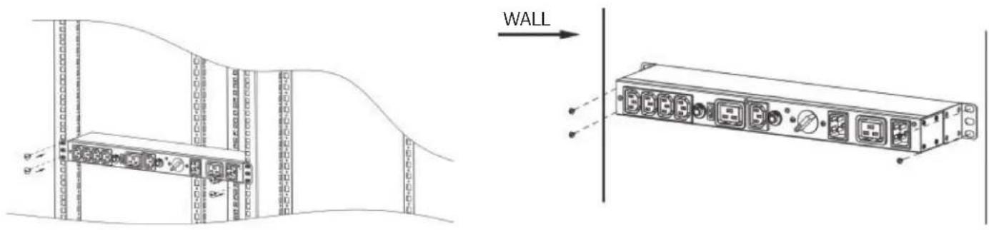
Figure 1: Rack Mounting Figure 2: Wall Mounting
2. Product Overview
PDUBHV101U
PDUBHV201U
PDUBHV20B
PDUB151U
PDUB201U
PDUBHV20D
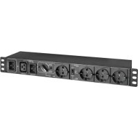
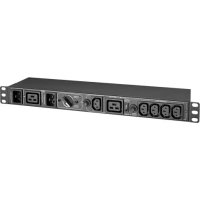
2. Product Overview
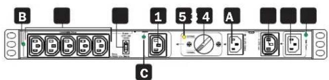
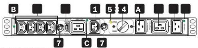
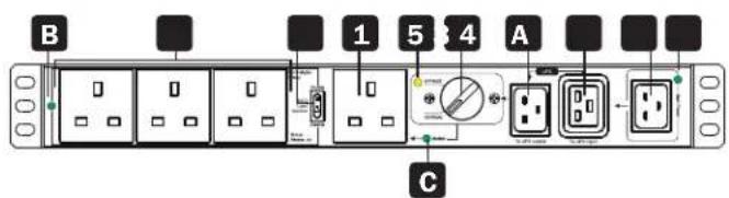
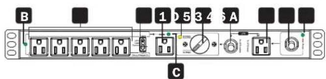
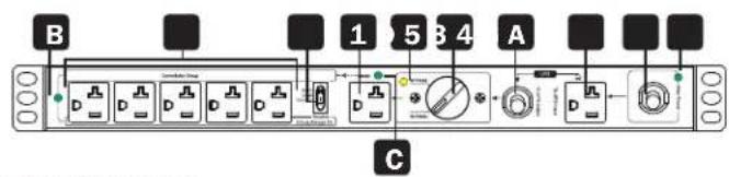
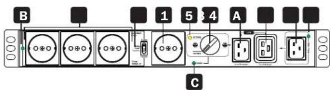
1 Master Output Receptacle(s)
UPS-supported outlet with optional current sense capability. This connection is labeled MASTER on the Bypass PDU.
2 Controllable Output Receptacle Group
UPS-supported outlets with optional power switching capability. These connections are labeled CONTROLLABLE GROUP on the Bypass PDU.
3 Protected UPS Input Power Connection
Connect to a protected UPS output receptacle. This connection is labeled TO UPS OUTPUT on the Bypass PDU.
4 Outlet for UPS Input Power Cord
Connect the UPS input cord here. This connection is labeled TO UPS INPUT on the Bypass PDU.
5 Bypass Switch
Set switch to NORMAL for standard protected UPS operation. Set switch to BYPASS during UPS replacement.
6 Mains AC Inlet/Cord
Connect AC input cord to any compatible mains power source. This connection is labeled MAIN POWER on the Bypass PDU.
7 Circuit Breaker (select models)
8 Enable ECO Load Control Switch
Select DISABLE for always-on operation of controllable outlets. Select ENABLE for optional ECO load-switching capability.
LED Indicators
A Mains AC Input (Green)
Illuminates to indicate mains AC cord/inlet (6) is live.
B Controllable Receptacle Group Output (Green)
Illuminates to indicate Controllable Receptacle Group (2) is live.
C Master Output Receptacle Output (Green)
Illuminates to indicate Master Output Receptacle (1) is live.
D Bypass Mode LED (Yellow)
Illuminates when the Bypass Switch is in the BYPASS position.
3. Important Safety Warnings

CAUTION!
Save these instructions. To safely operate this unit, read and follow all instructions carefully. Read this manual thoroughly before attempting to unpack, install or operate. Retain this manual for further reference.

- The unit is for indoor use only.
- Do not place the unit near liquid or in an excessively damp environment.
- Do not place the unit directly in the sun or near a source of heat.
- Do not let liquid or foreign objects enter the unit.
- Ground the unit using a 2P+ ground socket.
- This equipment is not suitable for use in locations where children are likely to be present.
- The appliance is intended to be installed and operated by a skilled person (qualified electrical technician).

- CAUTION: Electrical shock risk due to the multiple supply connections.
- Use tools with insulated handles.
- Do not touch the AC mains terminals or plug. Before working on the appliance, check for hazardous voltage between all AC mains terminals, both input plug and appliance inlet.
- When installing the unit, ensure the sum of the leakage currents of the unit and the devices it supplies does not exceed 3.5mA.
UPS Location Warnings
| Temperature | Operating 0°C to | 40°C (32°F to 104°F) |
| Storage -20°C to | 50°C (-4°F to 122°F) | |
| Elevation | Operating 0 m to | 3000 m (0 ft. to 9843 ft.): Normal Operation |
| Humidity | 0% to 95% Relative Humidity, Non-Condensing | |
| IP Rating | IP20 | |
4. Installation
Inspection
Remove the unit from the shipping package and inspect it for damage that may have occurred during transport. Notify the carrier and your dealer if any damage is found.
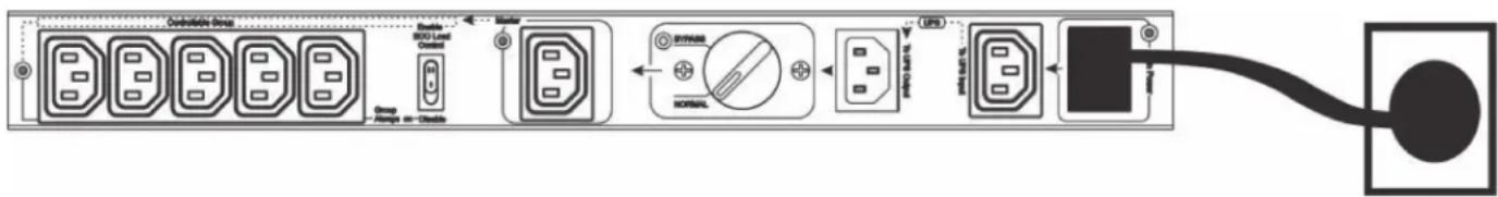
Connect to the Wall Outlet
Plug the Bypass PDU main input cord to an unprotected AC outlet. This connection is labeled MAIN INPUT on the PDU. The MAIN POWER LED will illuminate when mains input is available.
Note: For models PDUBHV101U and PDUBHV201U, you may need to use your UPS system's power cable to connect the Bypass PDU to the AC power source.
4. Installation
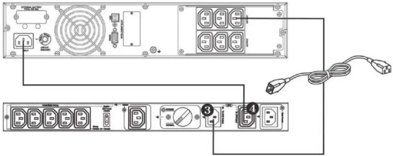
Connect UPS
- Connect the UPS input cord to the outlet for UPS input power cord (4). This outlet is labeled "To UPS Input" on the Bypass PDU.
- Connect the protected UPS input power connection on the Bypass PDU to a protected UPS outlet. This connection is labeled "To UPS Output" on the bypass PDU.
Note: For models PDUBHV101U and PDUBHV201U, use the supplied power cords to make these connections.
Protected UPS Input Power Connection
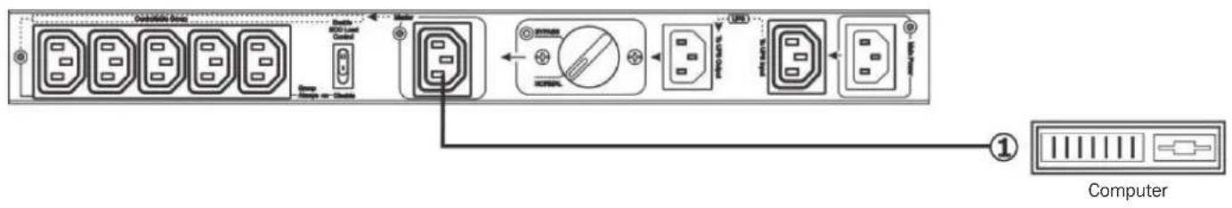
Connect Equipment
There are two types of outputs: Master and Controllable Group receptacles. Outlet functions are controlled by the ECO load control switch. When this switch is set to DISABLE, all outlets will operate in an always-on capacity. In this configuration, protected equipment can be connected to any outlet whether it is part of the Master or Controllable Group set of outlets for always-on operation during both Normal and Bypass Modes.
When the ECO load control switch is set to ENABLE, the device connected to the load-sensing Master outlet will offer automatic power OFF/ON control of the set of Controllable Group outlets. In this configuration, powering off the device connected to the Master outlet will automatically power off the devices connected to the Controllable Group outlets. Anytime the Master outlet current is measured to be 20W or less, the Controllable Group outlets will power off within 1 second.
4. Installation
Plug Computer into Controllable Output Receptacle
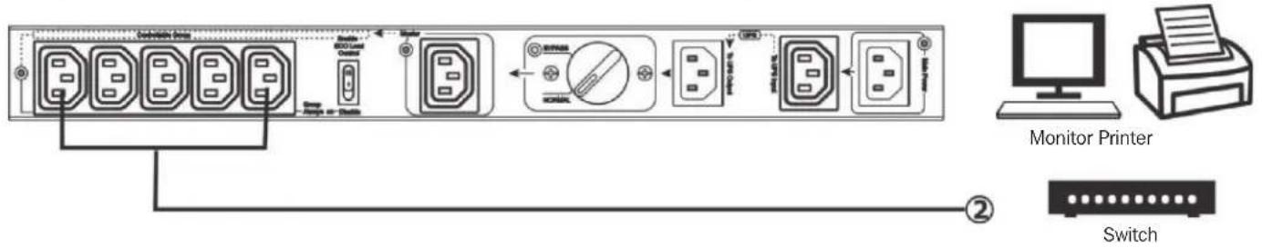
Plug Peripherals into Controllable Output Receptacle Group
Normal/Bypass Mode Operation
Before transferring to maintenance bypass, make sure the Main Power LED is illuminated. Transfer the rotary bypass switch from NORMAL to BYPASS. At this time, the Bypass Mode LED will illuminate and all connected devices will be powered by utility power directly. You may turn off the UPS and disconnect two cables connecting to the UPS. You may now service or replace the UPS.
Transfer to UPS Protection
After maintenance service is complete, ensure the UPS operation is normal. Reconnect the UPS to the unit by following the steps in section 4. Installation. Verify the Main Power LED is illuminated. Then transfer the rotary bypass switch from BYPASS to NORMAL. All connected devices are now protected by the UPS.
ECO Mode Function Operation
After connecting all devices to the unit, press the ECO Mode function switch to ENABLE status (.) The Controllable Receptacle Group LED will illuminate when the connected load on the master output is above 20W. Press the ECO Mode function switch to DISABLE status (△) to disable the function. The Controllable Receptacle Group LED will be illuminated.
4. Installation
Status Indicator Table
| ECO Mode Disabled ECO | Mode Enabled | |||||||||||
| Load Level | Any load level Master load | ad above threshold Master load below threshold | ||||||||||
| Mains Available | Yes | Yes | No | No | Yes | Yes | No | No | Yes | Yes | No | No |
| Transfer Switch Position | Normal | Bypass | Normal | Bypass | Normal | Bypass | Normal | Bypass | Normal | Bypass | Normal | Bypass |
| Mains AC Input LED | Green | Green Off | Off Green | Green | Off Off | Green | Green Off | Off | ||||
| Bypass Mode LED | Off | Yellow | Off | Off | Off | Yellow | Off | Off | Off | Yellow | Off | Off |
| Controllable Receptacle Group LED | Green | Green Green | Green Green | Green Green | Green Green | Green Green | Off Off | Off Off | ||||
| Master LED | Green when outlet is live at any power level | |||||||||||
5. Warranty & Product Registration
2-YEAR LIMITED WARRANTY
TRIPP LITE warrants its products to be free from defects in materials and workmanship for a period of two (2) years from the date of initial purchase. TRIPP LITE's obligation under this warranty is limited to repairing or replacing (at its sole option) any such defective products. To obtain service under this warranty, you must obtain a Returned Material Authorization (RMA) number from TRIPP LITE or an authorized TRIPP LITE service center. Products must be returned to TRIPP LITE or an authorized TRIPP LITE service center with transportation charges prepaid and must be accompanied by a brief description of the problem encountered and proof of date and place of purchase. This warranty does not apply to equipment, which has been damaged by accident, negligence or misapplication or has been altered or modified in any way.
EXCEPT AS PROVIDED HEREIN, TRIPP LITE MAKES NO WARRANTIES, EXPRESS OR IMPLIED, INCLUDING WARRANTIES OF MERCHANTABILITY AND FITNESS FOR A PARTICULAR PURPOSE.
Some states do not permit limitation or exclusion of implied warranties; therefore, the aforesaid limitation(s) or exclusion(s) may not apply to the purchaser.
EXCEPT AS PROVIDED ABOVE, IN NO EVENT WILL TRIPP LITE BE LIABLE FOR DIRECT, INDIRECT, SPECIAL, INCIDENTAL OR CONSEQUENTIAL DAMAGES ARISING OUT OF THE USE OF THIS PRODUCT, EVEN IF ADVISED OF THE POSSIBILITY OF SUCH DAMAGE. Specifically, TRIPP LITE is not liable for any costs, such as lost profits or revenue, loss of equipment, loss of use of equipment, loss of software, loss of data, costs of substitutes, claims by third parties, or otherwise.
Product Registration
Visit tripplite.com/warranty today to register your new Tripp Lite product. You'll be automatically entered into a drawing for a chance to win a FREE Tripp Lite product!*
* No purchase necessary. Void where prohibited. Some restrictions apply. See website for details.
FCC Notice, Class B
This device complies with part 15 of the FCC Rules. Operation is subject to the following two conditions: (1) This device may not cause harmful interference, and (2) this device must accept any interference received, including interference that may cause undesired operation.
Note: This equipment has been tested and found to comply with the limits for a Class B digital device, pursuant to part 15 of the FCC Rules. These limits are designed to provide reasonable protection against harmful interference in a residential installation. This equipment generates, uses and can radiate radio frequency energy and, if not installed and used in accordance with the instructions, may cause harmful interference to radio communications. However, there is no guarantee that interference will not occur in a particular installation. If this equipment does cause harmful interference to radio or television reception, which can be determined by turning the equipment off and on, the user is encouraged to try to correct the interference by one or more of the following measures:
- Reorient or relocate the receiving antenna.
- Increase the separation between the equipment and receiver.
- Connect the equipment into an outlet on a circuit different from that to which the receiver is connected.
- Consult the dealer or an experienced radio/TV technician for help.
Notice: The changes or modifications not expressly approved by the party responsible for compliance could void the user's authority to operate the equivalent.
WEEE Compliance Information for Tripp Lite Customers and Recyclers (European Union)

Under the Waste Electrical and Electronic Equipment (WEEE) Directive and implementing regulations, when customers buy new electrical and electronic equipment from Tripp Lite they are entitled to:
- Send old equipment for recycling on a one-on-one, like-for-like basis (this varies depending on the country)
- Send the new equipment back for recycling when this ultimately becomes waste.
Use of this equipment in life support applications where failure of this equipment can reasonably be expected to cause the failure of life support equipment or to significantly affect its safety or effectiveness is not recommended.
Tripp Lite has a policy of continuous improvement. Specifications are subject to change without notice. Photos and illustrations may differ slightly from actual products.


Manufacturing Excellence.
1111 W. 35th Street, Chicago, IL 60609 USA • tripplite.com/support
20-11-154 93-3C95_RevB
1111 W. 35th Street, Chicago, IL 60609 EE UU • tripplite.com/support
1111 W. 35th Street, Chicago, IL 60609 EE UU • tripplite.com/support
20-11-154 93-3C95_RevB
1111 W. 35th Street, Chicago, IL 60609 USA • tripplite.com/support
4. Installation
1111 W. 35th Street, Chicago, IL 60609 USA • tripplite.com/support
20-11-154 93-3C95_RevB
1111 W. 35th Street, Chicago, IL 60609 USA · tripplite.com/support
4. Установка
Подключение ИБП

1111 W. 35th Street, Chicago, IL 60609 USA - tripplite.com/support
- WARRANTY REGISTRATION
- Introduction
- Rack Mount or Wall Mount the Unit
- Product Overview
- Master Output Receptacle(s)
- Controllable Output Receptacle Group
- Protected UPS Input Power Connection
- Outlet for UPS Input Power Cord
- Bypass Switch
- Mains AC Inlet/Cord
- Circuit Breaker (select models)
- Enable ECO Load Control Switch
- LED Indicators
- A Mains AC Input (Green)
- B Controllable Receptacle Group Output (Green)
- C Master Output Receptacle Output (Green)
- D Bypass Mode LED (Yellow)
- Important Safety Warnings
- CAUTION!
- Installation
- Inspection
- Connect to the Wall Outlet
- Connect UPS
- Connect Equipment
- Normal/Bypass Mode Operation
- Transfer to UPS Protection
- ECO Mode Function Operation
- Warranty & Product Registration
- 2-YEAR LIMITED WARRANTY
- Product Registration
- FCC Notice, Class B
- WEEE Compliance Information for Tripp Lite Customers and Recyclers (European Union)
- Установка
- Подключение ИБП
Brand : Tripp Lite
Model : PDUBHV101U
Category : Electrical module