
SRXFANWM - Computer cooling system Tripp Lite - Free user manual and instructions
Find the device manual for free SRXFANWM Tripp Lite in PDF.

| Product Type | SmartRack Rack Enclosure Roof Fan Kit |
| Brand | Tripp Lite |
| Model | SRXFANWM |
| Category | Computer Hardware Cooling System |
| Use | Extracts hot air from SmartRack wall cabinets for optimal cooling |
| Installation | Mounts inside or outside on cabinet vents; secures with metal screws |
| Power | 120 V AC or 220-240 V AC depending on model; protected circuit max 20 A (120 V) or 16 A (220-240 V) |
| Materials | Metal housing, plastic fan blades |
| Airflow Direction | Reversible: exhaust or intake depending on arrow orientation |
| Safety | Overcurrent protection; mandatory grounding; do not block openings |
| Maintenance | No maintenance required; do not open fan |
| Spare Parts | Not available |
| Repairability | Not user serviceable |
| Warranty | 2-year limited warranty |
| Operating temperature | 0 °C to 40 °C |
| Environment | Controlled indoor, away from moisture and contaminants |
| Standards | Compliant with NEC ANSI/NFPA 70 (120 V) and Canadian Electrical Code |
| Kit contents | Fans, metal screws, adhesive cable anchors with ties |
Frequently Asked Questions - SRXFANWM Tripp Lite
User questions about SRXFANWM Tripp Lite
0 question about this device. Answer the ones you know or ask your own.
Ask a new question about this device
Download the instructions for your Computer cooling system in PDF format for free! Find your manual SRXFANWM - Tripp Lite and take your electronic device back in hand. On this page are published all the documents necessary for the use of your device. SRXFANWM by Tripp Lite.
USER MANUAL SRXFANWM Tripp Lite
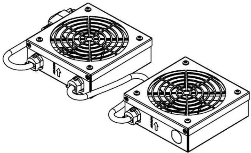
Panel-Mount Roof Fan Kit
Model: SRFANWM
(Series number: AG-0285)
natural_image
Technical line drawing of two heat exchangers with cooling fans and piping (no text or symbols)Español 6 • Français 11
PROTECT YOUR INVESTMENT!
Register your product for quicker service and ultimate peace of mind.
You could also win an ISOBAR6ULTRA surge protector—a \$100 value!
www.tripplite.com/warranty


Important Safety Instructions

SAVE THESE INSTRUCTIONS
This manual contains instructions and warnings that must be followed during the installation and operation of the product described in this manual. Read all instructions and warnings thoroughly before attempting installation. Failure to comply may affect the warranty and cause property damage and personal injury.
Connection, Installation and Location Warnings
- This manual includes instructional safeguards for the skilled person installing the fans.
- Inspect the shipping container and the unit for shipping damage. Do not use the unit if it is damaged.
- The fans are designed to be installed in commercial locations, such as IT data racks where only adults are normally present.
• Install in a controlled indoor environment, away from moisture, temperature extremes, flammable liquids and gasses, conductive contaminants, dust and direct sunlight. - For best performance, keep the indoor temperature between 32^ and 104^ ( 0^ and 40^ ).
- Do not attempt to modify or drill holes into the enclosure for mounting. Use the mounting holes provided.
• Install in accordance with National Electrical Codes (220-240V models).
• Install in accordance with National Electrical Code standards ANSI/NFPA 70 and Canadian Electrical Code, Part I, C22.1 (120V models). - To reduce the risk of fire, connect only to a circuit provided with branch circuit overcurrent protection in accordance with the National Electrical Code, ANSI/NFPA 70 and the Canadian Electrical Code, Part I, C22.1 (120V models).
- Be sure to use maximum 16A overcurrent protection, in accordance with the plug/equipment rating, for the installation (220-240V models).
- Be sure to use maximum 20A overcurrent protection, in accordance with the plug/equipment rating, for the installation (120V models).
- The equipment must be connected to an earthed ground mains socket-outlet.
- The plug on the power supply cord is intended to serve as the disconnect device. Be sure that the socket/outlet is installed near the equipment and easily accessible.
-
Appliance inlet models:
-
Use only approved SJT or H05W-F power cord types in accordance with national regulations.
- Use power cords with a minimum 18 AWG (1.0mm ^2 ) wire gauge.
-
Use only power cords with a protective earthing conductor and a socket outlet with an earthing connection.
-
Securely fasten the fans in place with screws.
- When using tools, use eye protection and follow all other safety precautions recommended by the tool manufacturer and required by applicable regulations.
- The fan does not require routine maintenance. Do not open the fan for any reason. There are no user-serviceable parts inside.
- Keep hair, clothing and loose objects away from the fan intakes. There is a risk of property damage and personal injury.
- Do not obstruct the fan openings. Do not block, cover or insert objects into the openings of the fan.
- Use of this equipment in life support applications where failure of this equipment can reasonably be expected to cause failure of the life support equipment or to significantly affect its safety or effectiveness is not recommended.
Explanation of Symbols
 | Caution, Risk of Danger |
 | Caution, Moving Fan Blades |
Recommended (Interior) Installation
Fans mounted inside the wall-mount enclosure draw air out of the cabinet to provide proper equipment cooling.
natural_image
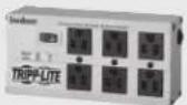
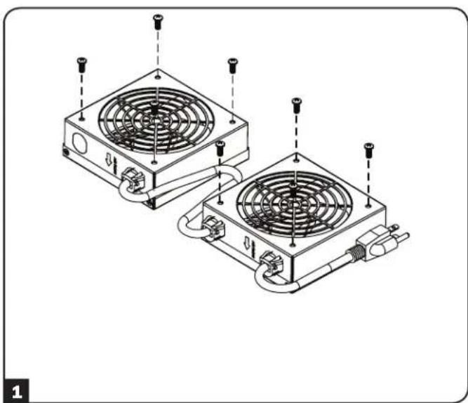
Technical line drawing of two heat exchangers with cooling fans and mounting screws (no text or symbols)1 Remove the metal screws from the vent shrouds.
2 For internal installation, place fan units inside the enclosure and position under the enclosure's vents. To draw warm air out of the enclosure, the airflow arrows should face up toward the top of the enclosure. Use the metal screws removed in step 1 to secure the fans to the enclosure.
Note: To draw cool air into the enclosure, flip the fan units so the airflow arrows point down.
natural_image
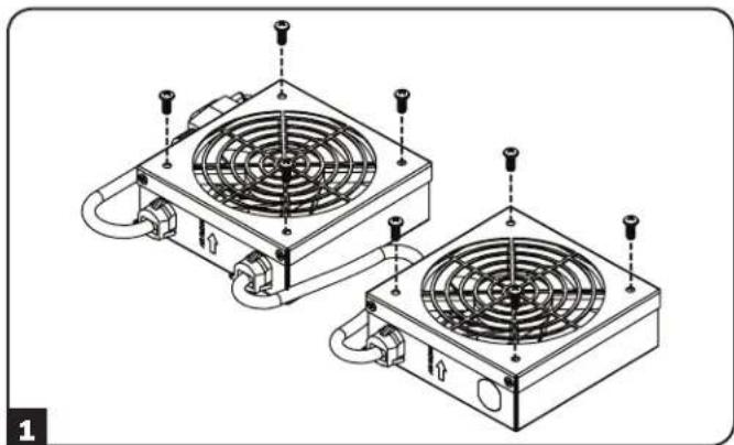
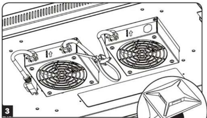
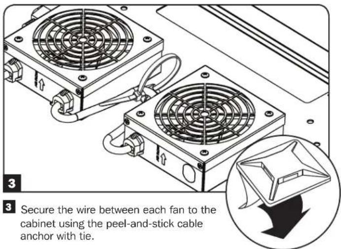
Technical line drawing of a computer front panel with two fans and ventilation slots (no text or symbols)3 Secure the wire between each fan to the cabinet using the peel-and-stick cable anchor with tie.
natural_image
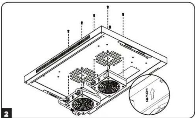
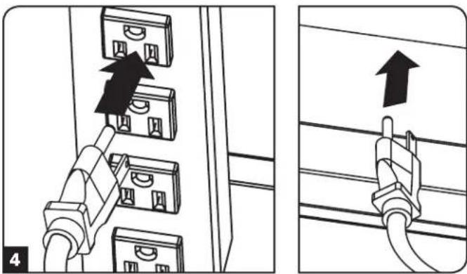
Diagram showing two installation steps of electrical connectors, one with a black arrow indicating the connection to a panel (no text or symbols present)4 Plug the input cable into a power source, such as an internal PDU. For external power connection, utilize the removable cable access panel.
Alternative (Exterior) Installation
Fans mounted outside the wall-mount enclosure draw air out of the cabinet for proper equipment cooling.
natural_image
Technical line drawing of two heat exchangers with cooling fans and mounting screws (no text or symbols)1 Remove the metal screws from the vent shrouds.
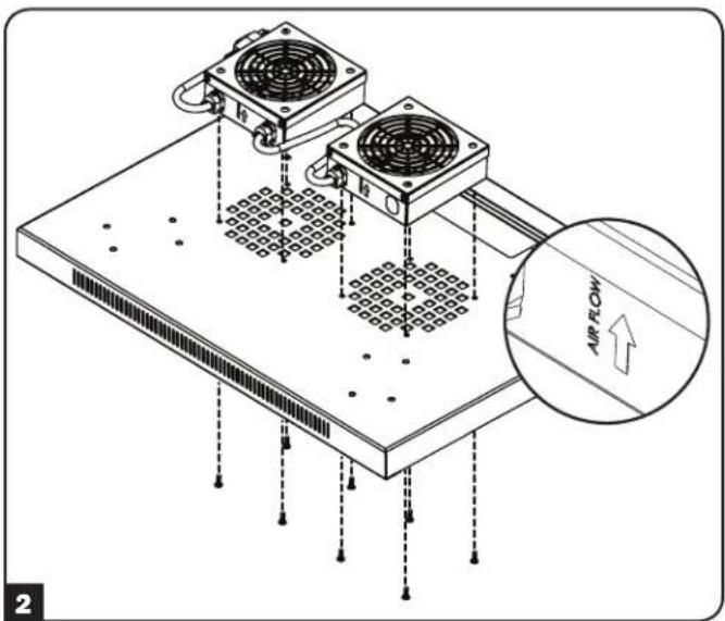
2 For external installation, place fan units outside of the enclosure and position on top of the enclosure's vents. To draw warm air out of the enclosure, the airflow arrows should face up. Use the metal screws removed in step 1 to secure the fans to the enclosure.
natural_image
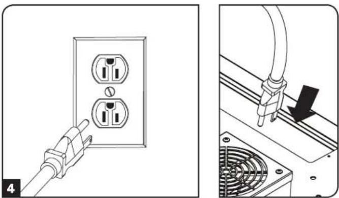
Diagram showing two installation steps: one of a plug inserted into an electrical outlet, the other of a cable with a plug inserted into a fan (no text or symbols present)4 Plug the input cable into a power source, such as a wall outlet. For connection to an internal PDU, utilize the removable cable access panel.
Warranty and Product Registration
2-Year Limited Warranty
Seller warrants this product, if used in accordance with all applicable instructions, to be free from original defects in material and workmanship for a period of 2 years from the date of initial purchase. If the product should prove defective in material or workmanship within that period, Seller will repair or replace the product, at its sole discretion. THIS WARRANTY DOES NOT APPLY TO NORMAL WEAR OR TO DAMAGE RESULTING FROM ACCIDENT, MISUSE, ABUSE OR NEGLECT. SELLER MAKES NO EXPRESS WARRANTIES OTHER THAN THE WARRANTY EXPRESSLY SET FORTH HEREIN. EXCEPT TO THE EXTENT PROHIBITED BY APPLICABLE LAW, ALL IMPLIED WARRANTIES, INCLUDING ALL WARRANTIES OF MERCHANTABILITY OR FITNESS, ARE LIMITED IN DURATION TO THE WARRANTY PERIOD SET FORTH ABOVE; AND THIS WARRANTY EXPRESSLY EXCLUDES ALL INCIDENTAL AND CONSEQUENTIAL DAMAGES. (Some states do not allow limitations on how long an implied warranty lasts, and some states do not allow the exclusion or limitation of incidental or consequential damages, so the above limitations or exclusions may not apply to you. This warranty gives you specific legal rights, and you may have other rights which vary from jurisdiction to jurisdiction).
WARNING: The individual user should take care to determine prior to use whether this device is suitable, adequate or safe for the use intended. Since individual applications are subject to great variation, the manufacturer makes no representation or warranty as to the suitability or fitness of these devices for any specific application.
Product Registration
Visit www.triplite.com/warranty today to register your new Tripp Lite product. You'll be automatically entered into a drawing for a chance to win a FREE Tripp Lite product!* *No purchase necessary. Void where prohibited. Some restrictions apply. See website for details.
Tripp Lite has a policy of continuous improvement. Specifications are subject to change without notice.


1111 W. 35th Street, Chicago, IL 60609 USA • www.tripplite.com/support
natural_image
Technical line drawing of two heat exchangers with cooling fans and piping (no text or symbols)English 1 • Français 11


1111 W. 35th Street, Chicago, IL 60609 EE UU • www.tripplite.com/support
natural_image
Technical line drawing of two heat exchangers with cooling fans and heat sinks (no text or symbols)natural_image
Technical line drawing of two heat exchangers with cooling fans and mounting screws (no text or symbols)natural_image
Diagram showing two electrical socket connections with a plug inserted, and a close-up of a fan installation (no text or symbols)natural_image
Technical line drawing of two heat exchangers with cooling fans and piping (no text or symbols)English 1 • Español 6


1111 W. 35th Street, Chicago, IL 60609 USA • www.tripplite.com/support
natural_image
Technical line drawing of two heat exchangers with cooling fans and heat sinks (no text or symbols)natural_image
Technical line drawing of two heat exchangers with cooling fans and mounting screws (no text or symbols)natural_image
Diagram showing two electrical socket installation steps: one with a plug, the other with a plug inserted into a fan (no text or symbols)1111 W. 35th Street, Chicago, IL 60609 USA • www.tripplite.com/support