SmartRack SRX12UBFFD - Wardrobe Tripp Lite - Free user manual and instructions
Find the device manual for free SmartRack SRX12UBFFD Tripp Lite in PDF.

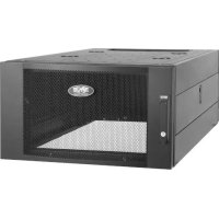
| Product Type | 19" (48.26 cm) rack enclosure, 12U |
| Brand | Tripp Lite |
| Model | SmartRack SR12UBFFD |
| Dimensions (H x W x D) | 637 x 600 x 980 mm (25 x 23.63 x 38.6 in) |
| Net weight | 43 kg (95 lb) |
| Maximum load capacity | 113 kg (250 lb) stationary or on casters |
| Adjustable mounting depth | 76 to 826 mm (3 to 32.5 in) |
| Rack units (U) | 12U |
| Front and rear doors | Lockable and reversible (opening direction) |
| Side panels | Lockable and removable |
| Casters | 4 casters included (SRCASTER accessory) |
| Leveling feet | 4 adjustable leveling feet |
| Air filter | Replaceable dust filter 20 x 24 x 1 in (one filter) |
| Ventilation | Vents with removable cover plates, cable routing slot |
| Mounting hardware | Vertical mounting rails with square holes, cage nuts and screws provided |
| Grounding | Grounding studs at all four corners, doors grounded |
| Power | AC input port; overcurrent protection 20 A max; power cord 18 AWG minimum |
| Installation environment | Controlled indoor environment, temperature 0 °C to 40 °C, avoid humidity and dust |
| Warranty | 5-year limited warranty |
| User manual | 24-page manual included, available for download |
Frequently Asked Questions - SmartRack SRX12UBFFD Tripp Lite
User questions about SmartRack SRX12UBFFD Tripp Lite
0 question about this device. Answer the ones you know or ask your own.
Ask a new question about this device
Download the instructions for your Wardrobe in PDF format for free! Find your manual SmartRack SRX12UBFFD - Tripp Lite and take your electronic device back in hand. On this page are published all the documents necessary for the use of your device. SmartRack SRX12UBFFD by Tripp Lite.
USER MANUAL SmartRack SRX12UBFFD Tripp Lite
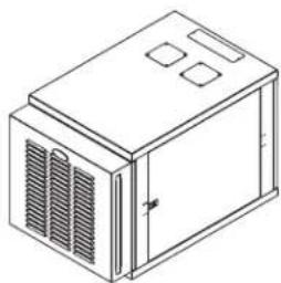
Agency Series: AG-04D4 with Fan Enclosure Door (Series: AG-053B)
24U SmartRack Enclosure
Model: SR24UBFFD
natural_image
Isometric line drawing of a rectangular industrial or electrical cabinet with ventilation grilles and three square cutouts (no text or symbols)Table of Contents
- Important Safety Instructions 2
- Overview 3
- Feature Identification 3
-
Enclosure Installation 4
4.1 Preparation 4
4.2 Unpacking 4
4.3 Installing Casters and Levelers 4
4.4 Placement 4
4.5 Leveling the Enclosure 5
4.6 Ground Connection 5 -
Enclosure Configuration 6
5.1 Door Locks 6
5.2 Reversing the Doors 6
5.3 Mounting Rails 6
5.4 Adjusting Mounting Rail Depth 6
5.5 Cleaning/Replacing Air Filters 7 - Equipment Installation 7
6.1 Installing or Removing Cage Nuts 7 - Specifications 8
- Storage and Service 8
- Warranty & Warranty Registration 8
Español 9
Français 17
WARRANTY REGISTRATION
Register your product today and be automatically entered to win an ISOBAR ^® surge protector in our monthly drawing!

tripplite.com/warranty


1111 W. 35th Street, Chicago, IL 60609 USA • tripplite.com/support
Copyright © 2020 Tripp Lite. All rights reserved.

SAVE THESE INSTRUCTIONS
This manual contains instructions and warnings that must be followed during the installation and operation of the product described in this manual. Read all instructions and warnings thoroughly before attempting installation. Failure to comply may affect the warranty and cause property damage and personal injury.
Connection, Installation and Location Warnings
- This manual includes instructional safeguards for the skilled person installing the cabinet with fans.
- Inspect the shipping container and the unit for shipping damage. Do not use the unit if it is damaged.
- The cabinet with fan is designed to be installed in a commercial location where only adults are normally present.
• Install in a controlled indoor environment, away from moisture, temperature extremes, flammable liquids and gasses, conductive contaminants, dust and direct sunlight. - For best performance, keep the indoor temperature between 32^ and 104^ ( 0^ and 40^ ).
- Leave adequate space at the front and rear of the enclosure for proper ventilation. Do not block, cover or insert objects into the external ventilation openings of the enclosure.
- The enclosure is extremely heavy. Use caution when handling the enclosure. Do not attempt to unpack, move or install it unassisted. Use a mechanical device such as a forklift or pallet jack to move the enclosure in the shipping container.
- Do not place any object on the enclosure, especially containers of liquid, and do not attempt to stack the enclosures.
- Leave the enclosure in the shipping container until it has been moved as close to the final installation location as possible.
• Install the enclosure in a structurally sound area capable of handling the load, or on a level floor that is able to bear the weight of the enclosure, all equipment that will be installed in the enclosure and any other enclosures and/or equipment that will be installed nearby. - Use caution when cutting packing materials. The enclosure could be scratched, causing damage not covered by the warranty.
- Save all packing materials for later use. Repacking and shipping the enclosure without the original packing materials may cause product damage that will void the warranty.
- Do not reship the enclosure with additional equipment unless the enclosure was shipped with a special shock pallet. The combined weight of the enclosure and installed equipment must not exceed the load capacity of the pallet. Tripp Lite is not responsible for any damage that occurs during reshipment.
- The casters are designed for minor position adjustments within the final installation area only. The casters are not designed for moving the enclosure over longer distances.
- When rolling the enclosure on its casters, always push it from behind; never pull it toward you.
- A rolling enclosure can cause personal injury and property damage if not properly supervised. If rolling the enclosure down a ramp is required, use extreme caution. Do not attempt to use ramps that have a slope steeper than 1:12.
- Be sure to install 25 pounds of equipment in the lower part of the cabinet for stability.
• Install in accordance with National Electrical Code standards ANSI/NFPA 70 and Canadian Electrical Code, Part I, C22.1.
• To reduce the risk of fire, connect only to a circuit provided branch circuit overcurrent protection in accordance with the National Electrical Code, ANSI/NFPA 70 and the Canadian Electrical Code, Part I, C22.1. - Be sure to use maximum 20A overcurrent protection, in accordance with the plug/equipment rating, for the installation.
- The equipment must be connected to an earthed ground mains socket-outlet.
- The appliance inlet and plug on the power supply cord is intended to serve as the disconnect device. Ensure the socket-outlet is installed near the equipment and is made easily accessible.
- Use only approved power cords types SJT in accordance with national regulations.
- Use power cords with a minimum 18 AWG (0.75 mm2) wire gauge.
- Use only power cords with a protective earthing conductor and a socket outlet with an earthing connection.
- When using tools, use eye protection and follow all other safety precautions recommended by the tool manufacturer and required by applicable regulations.
- The fan does not require routine maintenance, other than filter replacement. Be sure to replace the filter on a routine basis. Do not open the fan for any reason. There are no user-serviceable parts inside.
- Keep hair, clothing and loose objects away from the fan intakes. There is a risk of property damage and personal injury.
- Do not obstruct the fan openings. Do not block, cover or insert objects into the openings of the fan.
- Use of this equipment in life support applications where failure of this equipment can reasonably be expected to cause failure of the life support equipment or to significantly affect its safety or effectiveness is not recommended. Do not use this equipment in the presence of a flammable anesthetic mixture with air, oxygen or nitrous oxide.
Explanation of Symbols

Caution, Risk of Danger

Caution, Moving Fan Blades
2. Overview
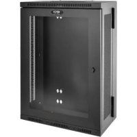
SmartRack Enclosures accommodate all standard 19-inch rackmount equipment, regardless of vendor, and ship fully assembled for quick and easy deployment.
3. Feature Identification
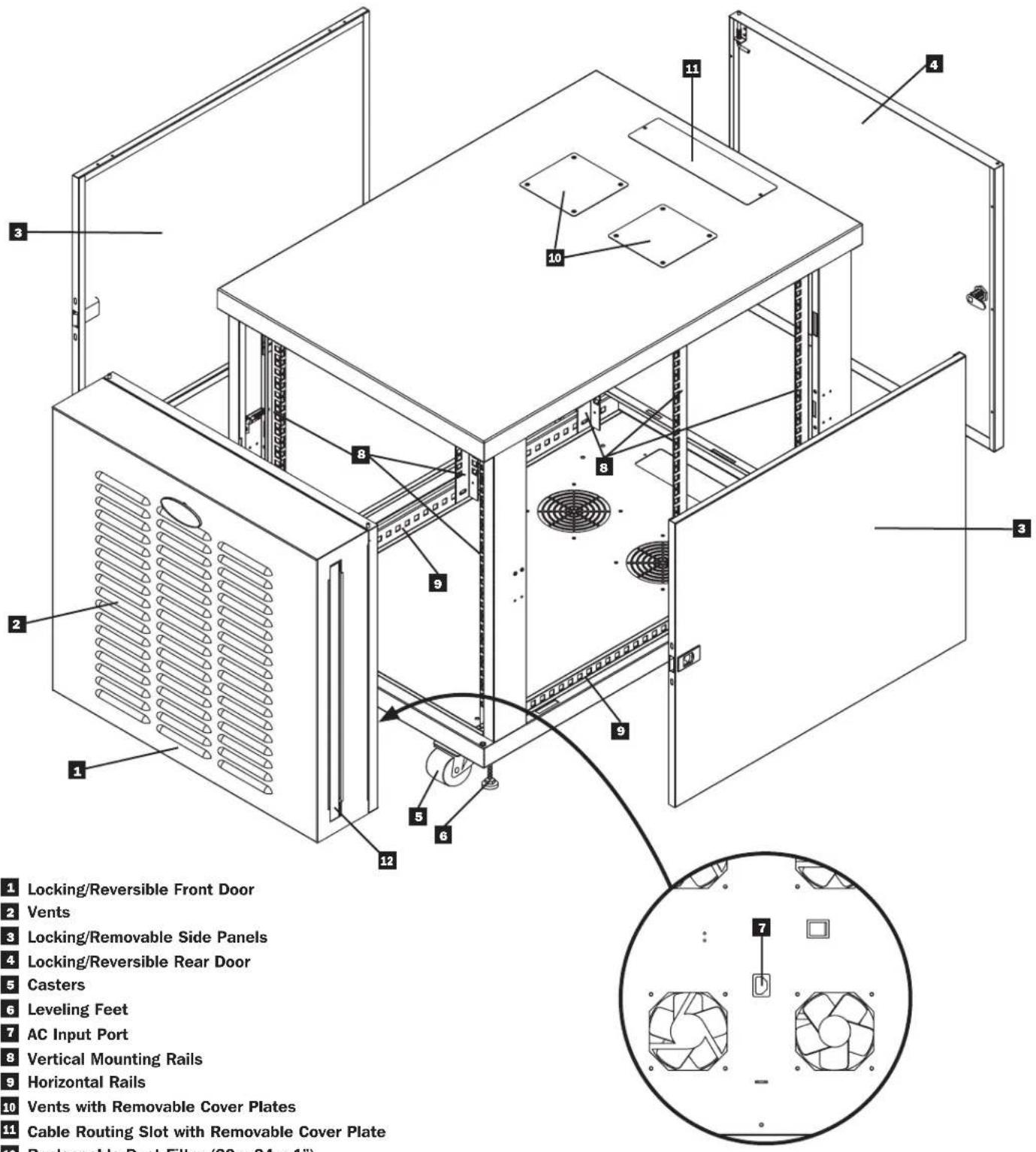
1 Locking/Reversible Front Door
2 Vents
3 Locking/Removable Side Panels
4 Locking/Reversible Rear Door
5 Casters
6 Leveling Feet
7 AC Input Port
8 Vertical Mounting Rails
9 Horizontal Rails
10 Vents with Removable Cover Plates
11 Cable Routing Slot with Removable Cover Plate
12 Replaceable Dust Filter (20 x 24 x 1")
x1 for SR12UBFFD
x2 for SR24UBFFD
4. Enclosure Installation

Caution! Read All Instructions and Warnings Before Installation!

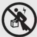
Warning: Rack enclosures can be extremely heavy. Do not attempt to unpack, move or install the enclosure without assistance. Use extreme caution when handling the enclosure and be sure to follow all handling and installation instructions. Do not attempt to install equipment without first stabilizing the enclosure.
4.1 Preparation
The enclosure must be installed in a structually sound area that is able to bear the weight of the enclosure, all the equipment that will be installed in the enclosure and any other enclosures and/or equipment that will be installed nearby. Before unpacking the enclosure, you should transport the shipping container closer to the final installation location to minimize the distance you will need to move the unit after the protective packaging has been removed. If you plan to store the enclosure for an extended period before installation, follow the instructions in the Storage and Service section.
You need several tools:
- Level
• 10 mm Open-End or Combination Wrench (2)
• 14 mm Open-End or Combination Wrench
• Phillips-Head Screwdriver
4.2 Unpacking

Use at least two people to unpack the enclosure.
1 Move shipping pallet to a firm, level surface.
2 Save all packing materials for later use unless you are certain they will not be required. Packing materials are recyclable.
3 With one person on each side, carefully lift the enclosure off of the pallet and place on a firm, level surface.
4 Examine the enclosure for any damage or loose parts. Confirm all parts are present. If anything is missing or damaged, contact Tripp Lite for assistance. Do not attempt to use the enclosure if it has been damaged.
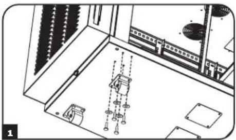
4.3 Installing Casters and Levelers
1 Installing Casters
Tripp Lite's accessory SRCASTER kit is included with your rack enclosure. This kit consists of 4 casters with required locknuts, washers and bolts for installation. Using two 10 mm open-end or combination wrenches, install the casters to the base of the unit using the pre-drilled holes near each corner of the enclosure.
Note: The unit has pre-threaded inserts for the casters. Locknuts are supplied with SRCASTERKIT, but are not needed for this execution.
2 Installing Levelers
There are 4 levelers included with your rack enclosure, 2 for the front and 2 for the rear. Using a 14 mm open-end wrench, install the levelers at the base of the unit using the threaded holes near each corner of the enclosure by turning the leveler in counter-clockwise. When the rack enclosure is moved to its installation location, use a 14mm open-end wrench to level the rack.
natural_image
Architectural floor plan showing room layout and structural elements (no text or labels)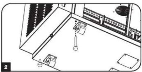
natural_image
Isometric line drawing of a room with furniture and fixtures, no visible text or symbols4.4 Placement
You can use the casters to move the enclosure for a short distance over a level, smooth, stable surface by pushing it from the front or rear (not the side panels). Do not attempt to roll the enclosure over long distances. The enclosure should be moved close to its installation location inside its shipping container before it is unpacked. Warning: Use appropriate equipment and follow all applicable safety procedures and regulations.

Warning: Never attempt to lift or install without adequate help. Do not try lifting the enclosure alone.

4. Enclosure Installation (continued)
4.5 Leveling the Enclosure

WARNING: Level the enclosure before attempting to install equipment. Install the enclosure in a structurally sound area with a level floor that is able to bear the weight of the enclosure, all equipment that will be installed in the enclosure and any other enclosures and/or equipment that will be installed nearby.
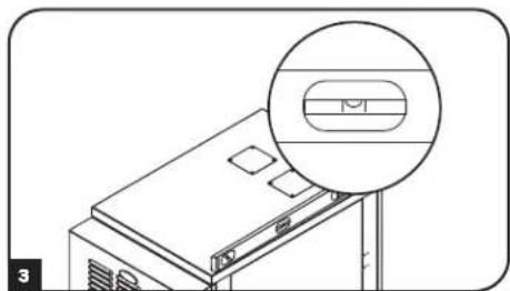
1 After the enclosure has been moved to the installation location, use a carpenter's level to check the slope of the floor. If the floor slopes more than 1%, choose an alternate installation site.
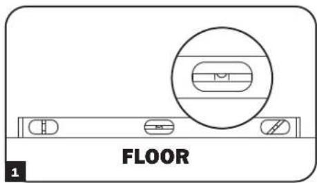
2 Use a 14 mm open-end wrench to lower each leveler A until it reaches the floor. (There are 4 levelers, 2 at the front and 2 at the rear.) Make sure each leveler contacts the floor solidly. Note: Lower a leveler by turning it clockwise; raise a leveler by turning it counter-clockwise.
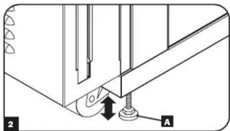
3 After lowering each leveler, use the carpenter's level to confirm that the enclosure is level in all directions. Adjust the levelers as required until the enclosure is level.
natural_image
Line drawing of a computer monitor with an inset magnified view showing internal components (no text or symbols)4.6 Ground Connection
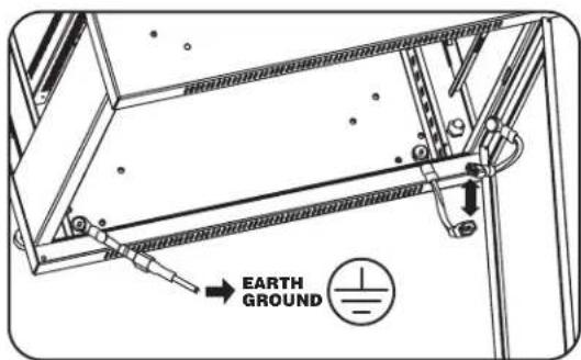
- All parts of the enclosure are grounded to the frame of the enclosure.
- Grounding studs have been provided in all four corners of the enclosure to allow for grounding in any configuration (including front or back door reversals).
- Grounding holes are also provided on top and bottom corners of both front and back doors to accommodate any configuration.
- To ground the enclosure simply connect the two quick-disconnect grounding wires, one to the hole provided on the inside of either the front or back door and the other to the stud provided in any corner of the enclosure. Connect your facility's earth ground connection to the grounding stud not used by door connections, using an 8 AWG (3.264 mm) wire.
Warning: Attach each enclosure to earth ground separately. Do not use the enclosure without an earth ground connection.
5. Enclosure Configuration
5.1 Door Locks
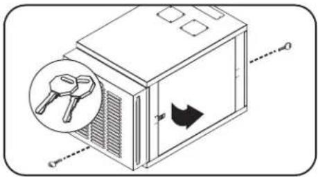
The front and back doors have locks that are accessible by the included keys. Each side panel locks using an L-shaped lever on the inside of the enclosure.
1 To unlock and remove the side panels, lift the shorter leg of the "L" up and pull it away from the side panel. Pull the tab on the side panel and remove it from the enclosure.
2 To re-lock the side panels, secure it in the proper position, lift the shorter leg of the "L" up and push it toward the side panel, back into the hole that it was in initially. Once it is in place, push the shorter leg of the "L" down to lock it. Note: To lock and unlock the side panels, you will need to have access to the interior of the enclosure.
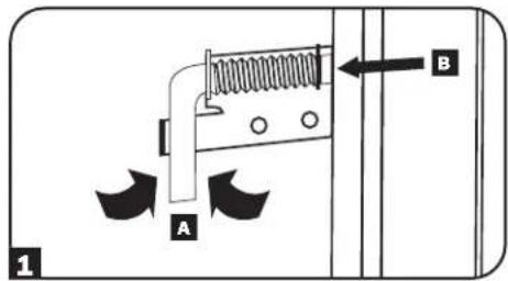
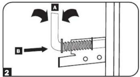
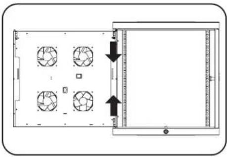
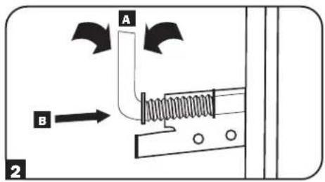
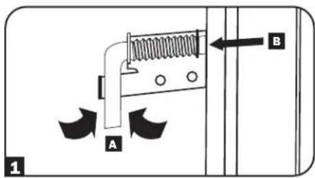
5.2 Reversing the Doors
The doors of the enclosure are held in position on the enclosure's frame with two spring-loaded pins. To reverse the door's swing direction, simply release the pins by pulling them up (lower pin) or down (upper pin) and remove them from the mounting holes on the frame of the enclosure.
Flip the door in the opposite direction and replace the pins in the identical mounting holes on the other side of the enclosure's frame by lining them up with the mounting holes and engaging them again.
natural_image
Diagram of a device rear panel with four fans and directional arrows indicating orientation (no text or symbols)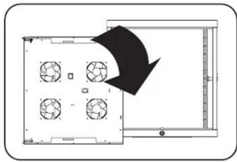
natural_image
Diagram of a device layout with four circular fans and a black arrow indicating direction (no text or symbols)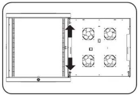
natural_image
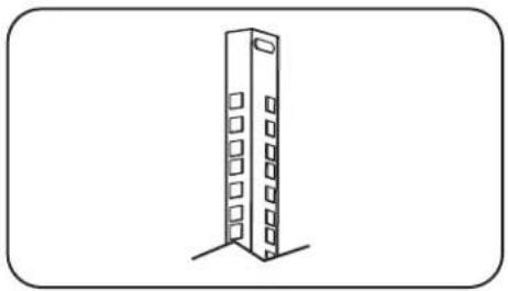
Diagram of a device front view showing internal components and directional arrows (no text or symbols)5.3 Mounting Rails
The enclosure comes with mounting rails that have square holes for mounting rack equipment. To install equipment, use the included cage nuts and other hardware. (See page 7 for installation of cage nuts.) Warning: Be sure to have the enclosure in its final position on the floor before mounting any equipment inside. Also be sure to have all the right adjustments on your rails before mounting equipment. (See below for Adjusting Mounting Rail Depth.)
natural_image
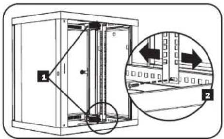
Simple line drawing of a tall building with windows and a corner support (no text or symbols)5.4 Adjusting Mounting Rail Depth
Warning: Do not attempt to adjust rails while equipment is installed in the enclosure. Do not attempt to use rails without screws installed. (2 per rail.)
The 4 mounting rails are pre-installed to accommodate equipment with a mounting depth of 20.5 inches (521 mm). Do not adjust the mounting rails unless your equipment requires a different mounting depth. The front and rear sets of rails can be adjusted independently for mounting of equipment with depths between 3 inches (76 mm) and 32.5 inches (826 mm).
1 Each rail is connected to the enclosure with 2 screws: 1 in the upper corner and another in the lower corner. Using a Phillips-head screwdriver, remove the screws that fasten the rails to the enclosure.
2 Slide the mounting rails to the desired depth and reattach them using the screws you removed in Step 1.
5. Enclosure Configuration
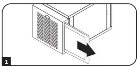
5.5 Cleaning/Replacing Air Filters
The enclosure comes with a pre-installed dust filter in the front door. SR12UBFFD uses one filter; SR24UBFFD uses two filters. It uses standard 20 x 24 x 1" filters that can be found at most home improvement stores. To remove filters for cleaning or replacement:
1 Locate filter on side of the front door and gently slide it out away from the unit.
2 Align clean/replacement filter with slot in door and slide it in until it reaches the end of its enclosure and you feel resistance.
Note: Part of the filter remains outside of the door for easy removal.
natural_image
Diagram of a microwave oven with ventilation grilles and a door, showing a black arrow pointing to the door (no text or symbols present)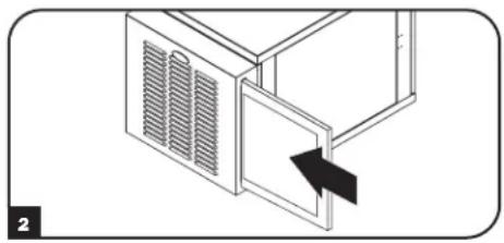
natural_image
Diagram of a microwave oven with ventilation grilles and a door, showing airflow direction (no text or symbols)6. Equipment Installation
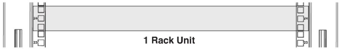
Warning: Do not install equipment until you have stabilized the enclosure. Install heavier equipment first and install it towards the bottom of the enclosure. Install equipment starting from the bottom of the enclosure and proceeding toward the top of the enclosure - never the reverse. If using sliding equipment rails, be careful when extending the rails. Do not extend more than one set of sliding equipment rails at one time. Avoid extending sliding equipment rails near the top of the enclosure.
Note: The square holes in the middle of each rack unit are numbered and also include a small notch to aid identification. A single rack unit includes the space occupied by the numbered hole and the holes directly above and below.
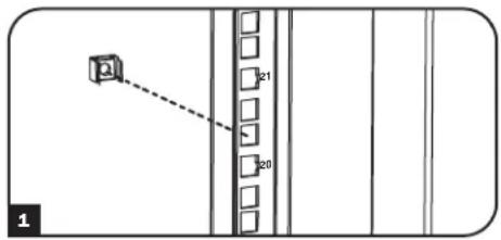
6.1 Installing or Removing Cage Nuts
WARNING: The flanges of the cage nuts should engage the sides of the square opening in the rail, not the top and bottom. Follow the instructions in your equipment documentation to ensure proper installation of your equipment.
1 Locate the numbered square openings in the mounting rails where you plan to install your equipment. You will install cage nuts (included) into the square openings in order to provide an attachment point for the mounting screws (included). Note: Consult your equipment documentation to determine how many cage nuts will be required and where they will need to be installed.
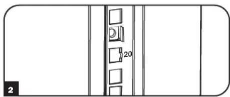
2 From the inside of the mounting rail, insert one of the flanges of the cage nut through the square opening. Press it against the side of the square opening. Each flange should engage one side of the square opening, not the top or bottom.
3 Compress the cage nut at the sides slightly to allow the remaining flange to fit through the square opening. When the cage nut is properly installed, both flanges will protrude through the square opening and will be visible on the outer surface of the mounting rail. Repeat steps 1-3 until all required cage nuts are installed.
4 After installing the required cage nuts, use the included mounting screws and cup washers to secure your equipment to the rack rail. Place the cup washers between the screws and the equipment mounting brackets.
Note: Your equipment may also include mounting hardware. Read the mounting instructions that came with your equipment before installing your equipment.
To Remove Cage Nuts, Reverse Steps 1-3
Note: You may wish to use a cage nut tool (user-supplied) to aid in cage nut installation and removal.
natural_image
Pure architectural floor plan lines without any text, numbers, or symbols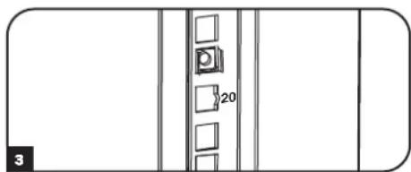
natural_image
Pure architectural floor plan lines without any text, numbers, or symbols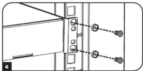
7. Specifications
| Model SR12UBFFD SR24UBFFD | ||
| Dimensions [H x W x D] 25 x 23 | 63 x 38.6 in. (637 x 600 x 980 mm) 46.8 x 23.63 x 38.6 in. (1188 x 600 x 980 mm) | |
| Unit Weight 95 lb. (43 kg) 209.4 | lb. (95 kg) | |
| Load Capacity 250 lb. (113 kg) | stationary or rolling 500 lb. (226 kg) stationary or rolling | |
| Mounting Depth (Adjustable) 3 to | 32.5 in. (76 to 826 mm) 3 to 32.5 in (76 to 826 mm) | |
8. Storage and Service
Storage
The enclosure should be stored in a controlled indoor environment, away from moisture, temperature extremes, flammable liquids and gasses, conductive contaminants, dust and direct sunlight. Store the enclosure in its original shipping container if possible.
Service
Your Tripp Lite product is covered by the warranty described in this manual. A variety of Extended Warranty and On-Site Service Programs are also available from Tripp Lite. For more information on service, visit triplite.com/support. Before returning your product for service, follow these steps:
- Review the installation and operation procedures in this manual to insure that the service problem does not originate from a misreading of the instructions.
- If the problem continues, do not contact or return the product to the dealer. Instead, visit tripplite.com/support.
- If the problem requires service, visit triplite.com/support and click the Product Returns link. From here you can request a Returned Material Authorization (RMA) number, which is required for service. This simple on-line form will ask for your unit's model and serial numbers, along with other general purchaser information. The RMA number, along with shipping instructions will be emailed to you. Any damages (direct, indirect, special or consequential) to the product incurred during shipment to Tripp Lite or an authorized Tripp Lite service center is not covered under warranty. Products shipped to Tripp Lite or an authorized Tripp Lite service center must have transportation charges prepaid. Mark the RMA number on the outside of the package. If the product is within its warranty period, enclose a copy of your sales receipt. Return the product for service using an insured carrier to the address given to you when you request the RMA.
9. Warranty & Warranty Registration
5-Year Limited Warranty
Seller warrants this product, if used in accordance with all applicable instructions, to be free from original defects in material and workmanship for a period of 5 years from the date of initial purchase. If the product should prove defective in material or workmanship within that period, Seller will repair or replace the product, at its sole discretion.
THIS WARRANTY DOES NOT APPLY TO NORMAL WEAR OR TO DAMAGE RESULTING FROM ACCIDENT, MISUSE, ABUSE OR NEGLECT. SELLER MAKES NO EXPRESS WARRANTIES OTHER THAN THE WARRANTY EXPRESSLY SET FORTH HEREIN. EXCEPT TO THE EXTENT PROHIBITED BY APPLICABLE LAW, ALL IMPLIED WARRANTIES, INCLUDING ALL WARRANTIES OF MERCHANTABILITY OR FITNESS, ARE LIMITED IN DURATION TO THE WARRANTY PERIOD SET FORTH ABOVE; AND THIS WARRANTY EXPRESSLY EXCLUDES ALL INCIDENTAL AND CONSEQUENTIAL DAMAGES. (Some states do not allow limitations on how long an implied warranty lasts, and some states do not allow the exclusion or limitation of incidental or consequential damages, so the above limitations or exclusions may not apply to you. This warranty gives you specific legal rights, and you may have other rights which vary from jurisdiction to jurisdiction.)
WARNING: The individual user should take care to determine prior to use whether this device is suitable, adequate or safe for the use intended. Since individual applications are subject to great variation, the manufacturer makes no representation or warranty as to the suitability or fitness of these devices for any specific application.
Warranty Registration
Visit triplite.com/warranty today to register the warranty for your new Tripp Lite product.You'll be automatically entered into a drawing for a chance to win a FREE Tripp Lite product!*
* No purchase necessary. Void where prohibited. Some restrictions apply. See website for details.
Regulatory Compliance Identification Numbers
For the purpose of regulatory compliance certifications and identification, your Tripp Lite product has been assigned a unique series number. The series number can be found on the product nameplate label, along with all required approval markings and information. When requesting compliance information for this product, always refer to the series number. The series number should not be confused with the marketing name or model number of the product.
Tripp Lite has a policy of continuous improvement. Specifications are subject to change without notice.


1111 W. 35th Street, Chicago, IL 60609 USA • tripplite.com/support
natural_image
Line drawing of a rectangular industrial cabinet with ventilation grilles and mounting holes (no text or symbols)Índice
1111 W. 35th Street, Chicago, IL 60609 USA • tripplite.com/support
natural_image
Architectural floor plan showing room layouts and structural elements (no text or labels)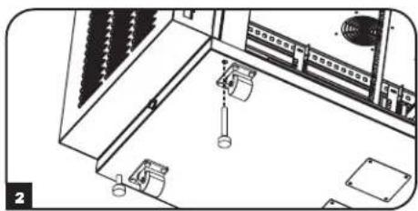
natural_image
Technical line drawing of an electrical cabinet with hanging components and wiring (no text or symbols)natural_image
Line drawing of a refrigerator with a magnified inset showing the front panel (no text or symbols)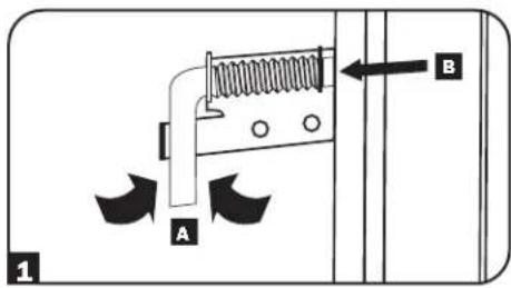
natural_image
Diagram of a rectangular device with four circular fans arranged in rows, showing directional arrows indicating movement or orientation (no text or symbols present)
natural_image
Top-down schematic of a device layout with four fans and a black arrow indicating direction (no text or symbols)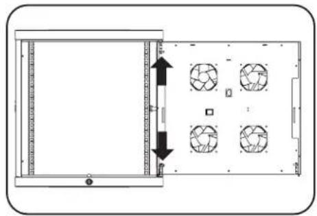
natural_image
Technical diagram of a rectangular panel with internal compartments and circular patterns, no visible text or symbolsnatural_image
Simple line drawing of a tall building with windows and a corner, no text or symbols presentnatural_image
Diagram of a microwave oven with a door and ventilation grille, showing airflow direction (no text or symbols)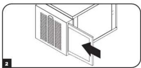
natural_image
Diagram of a microwave oven with ventilation grilles and a door, showing an arrow pointing to the door (no text or symbols present)natural_image
Simple line drawing of a cabinet or storage unit with four drawers and a vertical door, no text or symbols present.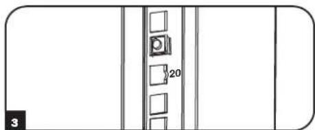
natural_image
Pure architectural line drawing of a building facade with vertical window and doorways (no text or symbols)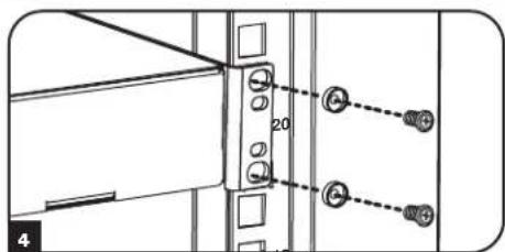
7. Especificaciones
| Modelo SR12UBFFD SR24UBFFD | ||
| Dimensiones [A x An x P] 25 x 23,63 | x 38,6 in. (637 x 600 x 980 mm) 46.8 x 23.63 x 38.6 in. (1 | 188 x 600 x 980 mm) |
| Peso de la unidad 95 lb. (43 kg) 209.4 lb. (95 kg) | ||
| Capacidad de carga 250 lb. (113 kg) | estacionario o rodante 500 lb. (226 kg) estacionario o rodante | |
| Profundidad de montaje (Ajustable) 3 | to 32,5 in. (76 to 826 mm) 3 to 32,5 in (76 to 826 mm) |
1111 W. 35th Street, Chicago, IL 60609 USA • tripplite.com/support
20-06-245 93-331E_RxO
natural_image
Isometric line drawing of a rectangular industrial cabinet with ventilation grilles and three recessed outlets (no text or symbols)Table des matières
1111 W. 35th Street, Chicago, IL 60609 USA • tripplite.com/support
natural_image
Technical line drawing of a mechanical assembly or enclosure with no visible text, numbers, or symbols.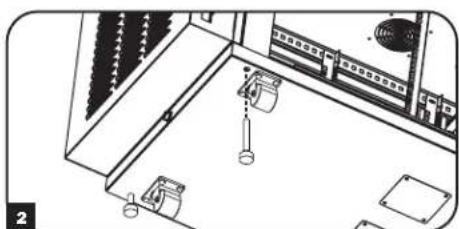
natural_image
Interior view of a room with furniture and fixtures, no visible text or symbolsnatural_image
Line drawing of a computer monitor with an inset magnified view showing a screen (no text or symbols)4.6 Mise à la terre

natural_image
Diagram of a device front view showing four circular fans arranged in rows, with arrows indicating directional movement (no text or symbols)
natural_image
Top-down schematic of a device layout with six circular fans and a black arrow indicating direction (no text or symbols)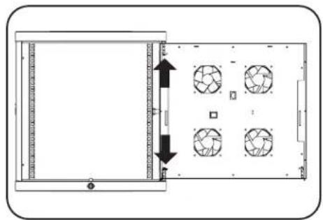
natural_image
Diagram of a device front view showing internal components and directional arrows (no text or symbols)natural_image
Simple line drawing of a tall building with windows and a corner support (no text or symbols)natural_image
Diagram of a microwave oven with ventilation grilles and a door, showing airflow direction (no text or symbols)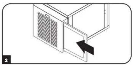
natural_image
Diagram of a microwave oven with ventilation grilles and a door, showing an arrow pointing to the door (no text or symbols present)1111 W. 35th Street, Chicago, IL 60609 USA • tripplite.com/support