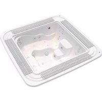
Verona - Bathtub ASTRALPOOL - Free user manual and instructions
Find the device manual for free Verona ASTRALPOOL in PDF.


| Product type | Massage spa / overflow pool or with skimmer |
| Brand | AstralPool |
| Model | Verona |
| Tub material | Acrylic |
| Main functions | Water massage, air massage, filtration, heating, ozonation, optional lighting |
| Power supply | Three-phase 400V between phases, 230V phase-neutral, 50/60 Hz |
| Heating power | 6000 W |
| Massage pump power (water) | Up to 2700 W per pump |
| Blower pump power (air) | 1300 W |
| Electrical safety device | Residual current device (RCD) 30 mA mandatory |
| Water temperature range | 34-40 °C, ideal 35-36 °C |
| Filtration system | Sand filter, filtration pump with flow detector |
| Water treatment | Bromine tablets (2.2-3.3 ppm) or chlorine (0.5-1.5 ppm), pH 7.2-7.6 |
| Additional disinfection options | Integrated ozonator |
| Acrylic surface maintenance | Clean with mild soap and water, polish with special wax; avoid solvents and abrasives |
| Maintenance during periods of non-use | Set low temperature, treat water, cover; in winter: drain and dry |
| Warranty | Subject to installation in accordance with instructions and by a professional |
| Spare parts | Only original, available from manufacturer or dealer |
| Compliance | EMC Directive 2014/30/EU, Low Voltage Directive 2014/35/EU, EN 60335-2-41 |
Frequently Asked Questions - Verona ASTRALPOOL
User questions about Verona ASTRALPOOL
0 question about this device. Answer the ones you know or ask your own.
Ask a new question about this device
Download the instructions for your Bathtub in PDF format for free! Find your manual Verona - ASTRALPOOL and take your electronic device back in hand. On this page are published all the documents necessary for the use of your device. Verona by ASTRALPOOL.
USER MANUAL Verona ASTRALPOOL
natural_image
Simple illustration of a blue rectangular object with a red X mark, no text or symbols present.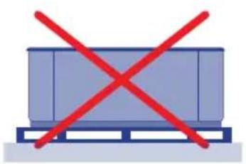
natural_image
Simple illustration of a blue container with red X marks on a wooden pallet (no text or symbols)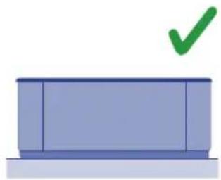
natural_image
Simple illustration of a blue rectangular box with a green checkmark above it (no text or symbols)201
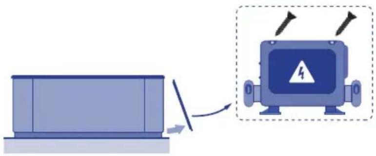
natural_image
Diagram showing a device transitioning from a rectangular block to an electric shock absorber with warning symbol (no text or labels)202
natural_image
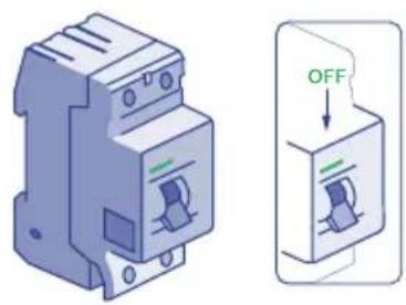
Illustration of a blue circuit breaker with a green 'OFF' button, shown alongside its side view (no text or symbols on the device itself)203
text_image
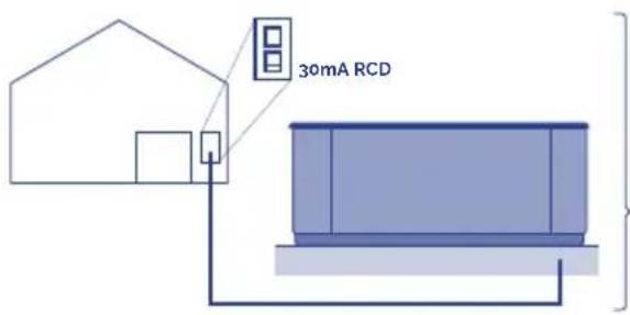
30mA RCDm
KW
| KW required | |||||||||||
| 2.1 2 | 5 2,8 3 | 2 3 5 | 5 3 | 6.2 7.0 | 7 4.8 8 | ||||||
| Distance | Nominal section of the cable in mm2 | ||||||||||
| 6 - 11 m 2 | 5 2,5 2 | 6 2,5 4 | 6 10 | 10 10 | 10 | 4 | |||||
| 11 - 15 m | 2,5 | 2,5 | 4 | 4 | 4 | 6 | 6 | 10 | 10 | 10 | 10 |
| 15 - 20 m 4 | 4 4 6 | 6 10 | 10 10 | 16 16 | 6 | ||||||
204
5.6.
natural_image
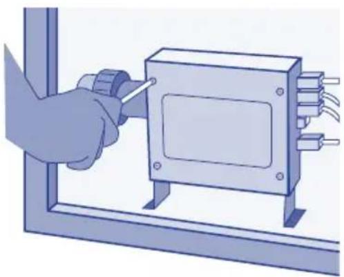
Illustration of a hand using a tool to adjust or install an electrical component on a metal frame (no text or symbols visible)205
natural_image
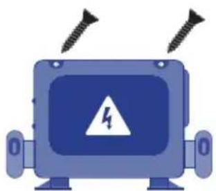
Illustration of a blue robot with two screws above it and a warning symbol inside (no text or labels)206
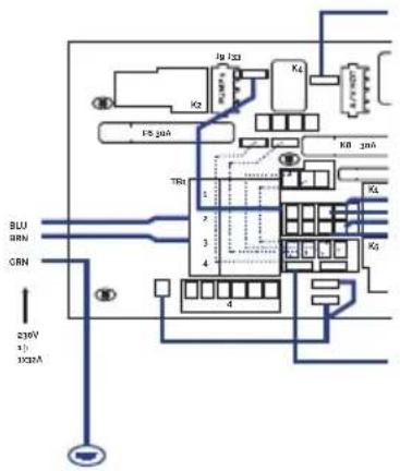
6a - Single phase
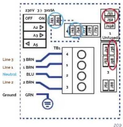
6b & 6c - Three phase
6a. 6b.
text_image
FU 133 K2 FU 20A KB 20A TR1 1 2 3 4 5 6 7 8 9 10 11 12 13 14 15 16 17 18 19 20 21 22 23 24 25 26 27 28 29 30 31 32 33 34 35 36 37 38 39 40 41 42 43 44 45 46 47 48 49 50 51 52 53 54 55 56 57 58 59 60 61 62 63 64 65 66 67 68 69 70 71 72 73 74 75 76 77 78 79 80 81 82 83 84 85 86 87 88 89 90 91 92 93 94 95 96 97 98 99 100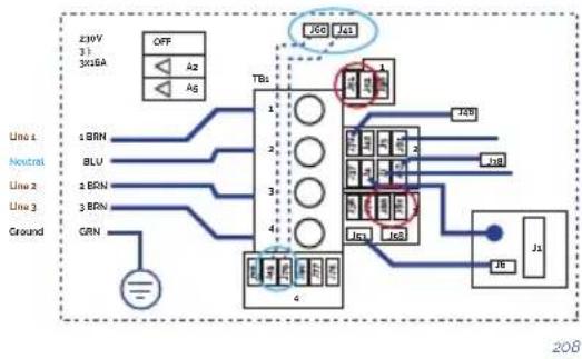
flowchart
graph TD
    A["Line 1: ZMW 3: 3x26A"] --> B["OFF"]
    B --> C["Az"]
    B --> D["Ag"]
    E["Line 2: 1 BRN 2 BLU 3 BRN 3 GRN"] --> F["TBs"]
    F --> G["1"]
    F --> H["2"]
    F --> I["3"]
    F --> J["4"]
    K["Ground"] --> L["JBL"]
    M["Line 3: JBL"] --> N["JBL"]
    O["Ground"] --> P["JBL"]
Three-phase line 380V III BP21G1WL
Remove bridges;
J51-J88 and J52-J62

Changes this bridges
J60-J36 -> TO J60-J45
J41-J12 -> TO J41-J79

Power requirements:
3 Services 5 wires: Line 2, Line2, Line 3, Neutral. Ground 400VCA, 50/60Hz 3 phase, 16A (Circuit breaker rating - 20A max each phase line).
Single line 230V 32A
6c.
flowchart
graph TD
    A["230V 3"] --> B["OFF ON"]
    B --> C["A2 ▶"]
    B --> D["A3 ▶"]
    B --> E["A5"]
    F["3 BRN"] --> G["TLB1"]
    H["1 BRN"] --> G
    I["BLU"] --> G
    J["2 BRN"] --> G
    K["GRN"] --> G
    L["4"] --> M["1"]
    L --> N["2"]
    L --> O["3"]
    P["745"] --> Q["746"]
    R["77"] --> S["779"]
    T["77"] --> U["779"]
    V["73"] --> W["73"]
    X["73"] --> Y["73"]
    Z["73"] --> AA["73"]
    AB["Unfused"] --> AC["3"]
    AD["Ground"] --> AE["Ground"]
Three-phase line 400V BP013G1 & BP013G2
Remove jumpers:
connecting J51 and J58
connecting J52 and J36

Changes this bridges:
J41 - J53 -> TO J41 - J54
J60-J12 -> TO J60-J45

Put DIP switches A5 on OFF and
A2, A3 on ON position.
Power requirements:
3- Service 5 wires: Line 2, Line
- Line 3, Neutral, Ground
400VCA, 50/60 Hz* 3 phase, 16A
(Circuit breaker rating = 20A max
each phase line). *BP systems
automatically detect 50Hz vs 60Hz
natural_image
Diagram of a container with a curved pipe pouring liquid into it, no text or symbols present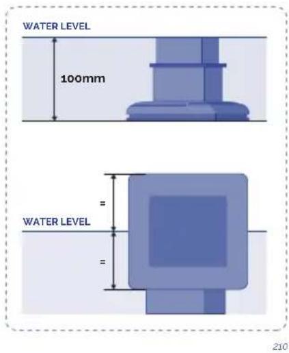
text_image
WATER LEVEL 100mm WATER LEVEL = = 2108.9.10.
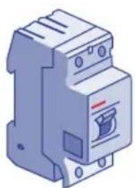
natural_image
Illustration of a blue electrical fuse with mounting holes and a warning symbol (no text or labels)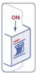
text_image
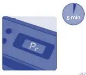
Pr 5 min 212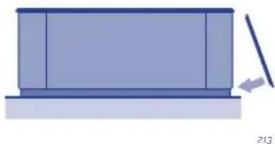
natural_image
Simple diagram of a rectangular container with a vertical rod and an arrow pointing to it, no text or symbols present.
text_image
QR code image containing encoded data, no visible human-readable text
text_image
QR code image containing encoded data, no visible human-readable texthttps://www.youtube.com/watch?v=EvKx_CkS_tw
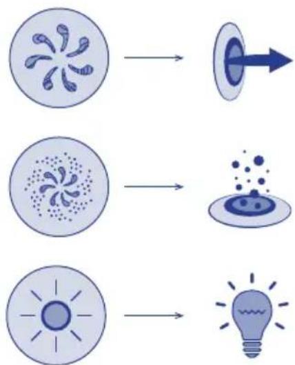
flowchart
graph TD
    A["Cell with star-like structure"] --> B["Target"]
    C["Cell with dendritic pattern"] --> D["Target"]
    E["Cell with sun-like shape"] --> F["Light bulb"]
heatmap
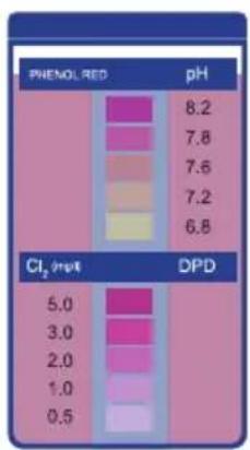
| pH | Phenol RED | Cl₂ (mEq) | DPD | |---|---|---|---| | 8.2 | | 5.0 | | | 7.8 | | 3.0 | | | 7.6 | | 2.0 | | | 7.2 | | 1.0 | | | 6.8 | | 0.5 | |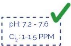
text_image
pH: 7,2 - 7,6 Cl₂: 1-1,5 PPM214 215
! ATTENTION
Remember this instructions manual contains fundamental information on the safety measures to be adopted when installing, starting-up and operating the spa. It is therefore essential that both the Fitter and the User read these instructions before assembly and start-up.
THE PRODUCT GUARANTEE WILL ONLY BE APPLIED IF IT IS CORRECTLY INSTALLED AND IF THE INSTRUCTIONS IN THE MANUAL HAVE BEEN COMPLIED WITH.
CHECK THE GUARANTEE SHEET AND CAREFULLY READ THE LIMITATIONS CONTAINED WITHIN.
CONTENTS
- INTRODUCTION ....7
- WARNINGS AND PREVENTIVE MEASURES....7
- INSTALLATION......8
3.1. Installation preventive measures....8
3.2. Installation description....8
3.3 Handling and locating the spa 14
3.4. Advices to build foundations....15
3.5. Electrical connections....18
3.6. Hydraulic connection 24
- START UP 29
- OPERATING INSTRUCTIONS....30
5.1. Warnings ....30
5.2. Remote control (Spa buttons)....32
- MAINTENANCE 33
6.1. Maintenance warnings ...... 33
6.2. Acrylic maintenance....33
6.3. Maintenance in periods of non-use or absence 33
6.4. Water maintenance .... 34
- ERROR CODES 38
- PROBLEMS AND SOLUTIONS......39
- RECYCLING AND ENVIRONMENT 40
- EVIDENCE OF CONFORMITY ...... 41
1. INTRODUCTION
This manual contains all the necessary information for fully enjoying your Spa. We suggest you take some time to go over the points below.
The Spa is an element designed especially for bathrooms, offering a bath/massage combination.
It consists of a closed water circuit powered by pumps which, combined with air, produce a relaxing massaging effect on your body.
For the massage bath to be effective, the water in the circuit must be at a temperature of between 34^ C and 37^ C, which is achieved by means of an electric heat exchanger.
If you have any questions or queries regarding the operation or maintenance of this product, contact the installer or your local distributor. They are specialised professionals and their knowledge will make things easier for you and will help you to enjoy this product.
IMPORTANT: The manufacturer reserves the right to change part of the designs or specifications without prior notice and without incurring in any obligations.
2. WARNINGS AND PREVENTIVE MEASURES
• Take all precautions to avoid unauthorised access of children inside the Spa. In order to avoid accidents, ensure children are supervised by an adult at all times. Control entering and exiting the Spa in order to avoid slips due to wet surfaces.
- Do not allow anyone to play inside the Spa with metal or sharp objects that could damage the acrylic surface.
- Make sure that bathers cannot access any of the Spa's electrical components.
- Do not turn on the machine without there being water inside the Spa.
- Do not use electrical devices such as radios or dryers inside the Spa.
- Always keep the minimum water level indicated in the skimmer (in the case of private use Spas) or that indicated in the level probes of the surge tank in the case of public use Spas.
3. INSTALLATION
3.1. Installation preventive measures
- A qualified professional must install, start and perform maintenance on the system in strict adherence to the installation instructions and following all indications given.
- This system may not be plugged into a domestic power line. Verify that the characteristics of the electrical installation meet the system requirements: 3 phases, 400V between each phase and 230V between phase and neutral.
- It is mandatory to comply with all applicable electrical safety standards of the country where the system is installed.
- The safety of people and materials should be ensured. Regulations and established safety codes must be respected.
- The electrical input of the system should always be protected by a highly sensitive RCD (Residual Current Device).
- Use only the highest quality connection, which must be grounded.
- It is essential to choose the appropriate cross section for the cables.
- Check that the thermal magnetic circuit breakers have been calibrated according to the power consumption (amperage).
- Never use the electric control box to connect other equipment.
- No modification is permitted without the express consent of the manufacturer.
- Use only original spare parts supplied by the manufacturer.
- Some elements of the equipment operate at dangerously high voltage. Do not handle them if the system is not completely disconnected from the power supply and start up devices are blocked.
- The limit values which appear on the electric switchboard must not, under any circumstance, exceed the advised amperage.
- Check the wiring and hydraulics before booting the system or connecting it to the power.
- Make sure that no electric component is in contact with water.
- Do not handle the equipment with wet feet.
- Do not switch on the system if the Spa is empty.
3.2. Installation description
GENERAL DIAGRAM
• SPA WITH OVERFLOW
Spas with overflows can redirect the water displaced by users into a balance tank, always maintaining a stablewater level inside the Spa tub.
See below a general diagram of the installation of this type of Spa.
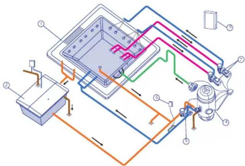
text_image
Technical diagram of a smart air conditioning system with numbered components and airflow paths1 Spa
2 Balance tank
3 Filter pump
4 Filter
5. Electric heating
6 Ozonator
7 Massage pumps
8 Blower pump
9. Electric operation cabinet
101
- SPA WITH SKIMMER
Spas without overflows have a different setup. No balance tank is required; instead, the Spa water is suctioned directly via a skimmer. When users enter the Spa, thewater level rises; the tub may overflow if the number of users exceeds the indications for each Spa.
The installation of both Spas with overflows and Spas with skimmers include the recirculation circuit, water massage, air massage and an electrical installation, all of which are detailed below.
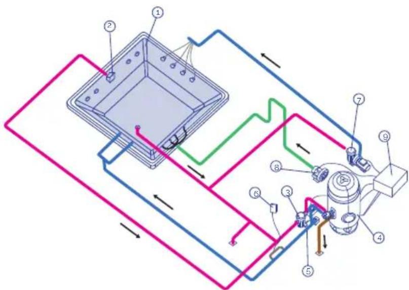
text_image
Technical diagram of a mechanical or electrical device with numbered components and directional arrows indicating flow or movement.1 Spa
2 Skimmer
3 Filter pump
4 Filter
5 Electric heating
6 Ozonator
7 Massage pumps
8 Blower pump
9 Electric operation cabinet
102
RECIRCULATION CIRCUIT
The function of this circuit is to maintain the quality of the Spa water. This is achieved by means of water recirculation through a purification filter, a heating system and a disinfection system.
• SPA WITH OVERFLOW
Given that the Spa has an overflow, it is essential to maintain the water level constant and at maximum level. In order to achieve this, it is necessary to install a balance tank installed in series with the recirculation circuit. Doing so will compensate the fluctuations in level caused by variations in the number of bathers.
Although there are different ways of setting up the recirculation circuit, we proceed to detail the two most popular systems: "Floor suction" and "Floor return". Check the regulations in force in each country in order to establish which system is best.
SPA FLOOR SUCTION
This option makes it possible to collect part of the recirculationwater from the Spa floor drain.
The filtered water is absorbed both from the balance tank (mostly) and the Spa floor drain via the filter pump, and is directed towards the sand filter, the heating and the ozonator or disinfection system; to be directed towards the Spa via the return nozzles.
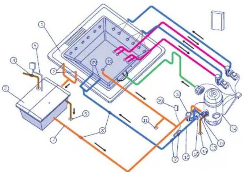
text_image
Technical diagram of a mechanical or electrical device with numbered components and colored flow paths indicating connections.1 Overflow
2 Overflow drains
3 Balance tank
4 Filling solenoid valve
5 Level probes
6 Balance tank drain
7 Balance tank suction
8 Anti-return valve
9 By-pass valve
10 Drain
11 Spa drainpipe
12 Filter pump
13 Selector valve
14 Filter
15 Filter drainpipe
16 Electric Heating
17 Temperature probe
18 Flow detector
19 Ozonator
20 Spa return nozzles
103
SPA FLOOR RETURN
This option allows you to direct part of the already filtered and heated water both via the return nozzles and via the Spa floor drain.
The filtered water is only suctioned from the balance tank by the filter pump and is directed toward the sand filter, the heating and the ozoniser or disinfection system, to then be directed towards the Spa via the return nozzles and the Spa floor drain.
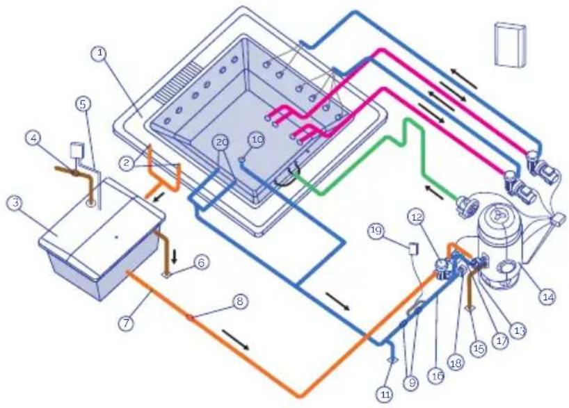
text_image
Technical diagram of a mechanical or electrical device with numbered components and colored wiring paths1 Overflow
2 Overflow drains
3 Balance tank
4 Filling solenoid valve
5 Level probes
6 Balance lank drain
7 Balance tank suction
8 Anti-return valve
9 By-pass valve
10 Drain
11 Spa drainpipe
12 Filter pump
13 Selector valve
14 Filter
15 Filter drainpipe
16 Electric Heating
17 Temperature probe
18 Flow detector
19 Ozonator
20 Spa return nozzles
• SPA WITH SKIMMER
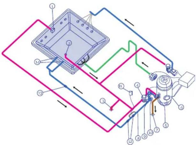
text_image
Technical diagram of a mechanical or electrical device with numbered components and directional arrows indicating flow or movement.104
1 Skimmer
2 Drain
3 Spa drainpipe
4 Filter pump
5 Selector valve
6 Filter
7 Filter drainpipe
8 Electric heating
9 Temperature probe
10 Flow detector
11 Ozonator
12 By-pass valve
13 Check valve
14 Spa return nozzles
205
HEATING CIRCUIT
The basic components present in all heating circuits are:
- FILTER PUMP
Designed to carry out the filter and heating circuit, recycling the water of the Spa in approximately 6 to 20 minutes. Suctions from the Skimmer or Surge Tank, directing the water through the filter and electric heating, via the return nozzle.
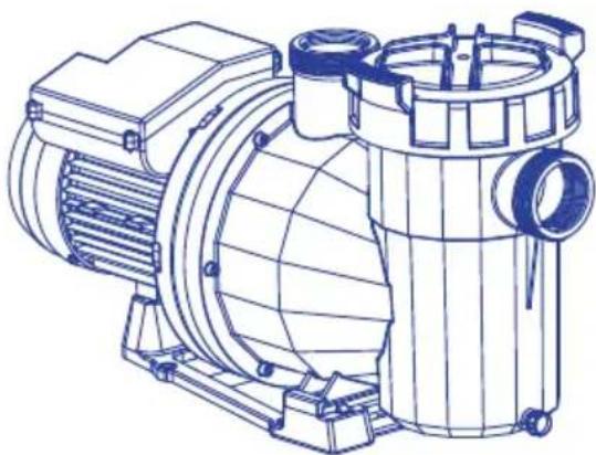
natural_image
Technical line drawing of an electric motor with internal components and mounting base (no text or labels)106
• ELECTRIC HEAT EXCHANGER
This makes it possible to maintain the desired temperature. It must be placed in the filter circuit after the filter, so as to avoid air bubbles accumulating inside.
The heat exchanger incorporates a safety thermostat with manual reset. This avoids the heat exchanger from being damaged if the Spa is started up without any water circulating.
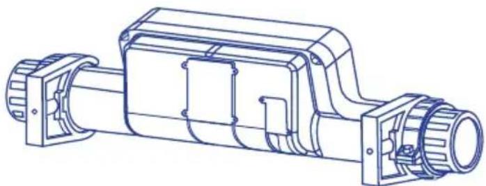
natural_image
Technical line drawing of a mechanical assembly with cylindrical components and mounting brackets (no text or symbols)107
• FILTER
Element which filters in order to ensure the water is of an adequate quality.
The size of the filter is determined on the basis of:
• Volume of the Spa.
• Water recirculation time.
- Filtering speed.
- Filtering surface.
- FLOW SENSOR
Safety device designed to prevent the heat exchanger from operating if there is no water flow in the filtration circuit.
WATER MASSAGE CIRCUIT
The water is suctioned by the massage pump through the drainpipes and is returned to the Spa via high speed jets.
There can be several massage circuits in a single Spa, each activated by a massage pump. Depending on the Spa and the number of jets it has, there may be one, two or even three massage pumps.
In order to boost the water massage a connection is made with an ambient air intake. This way, when the water circulates through, thanks to the Venturi effect, the air is suctioned, creating the air-water mix and producing a more intense massage.
Keep reading to see the general diagram of water spa massage.
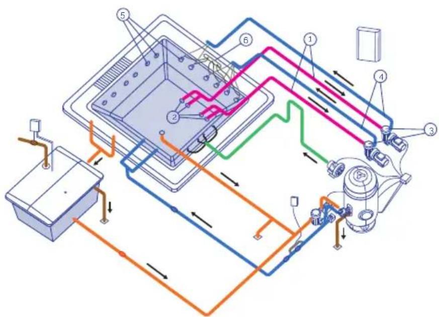
text_image
Technical diagram of a device's internal circuit with numbered components and directional flow arrows1 Suction circuit
2 Spa suction drainpipes
3 Massage pump
4 Water return circuit
5 Massage jets
6 Air suction circuit
AIR MASSAGE CIRCUIT
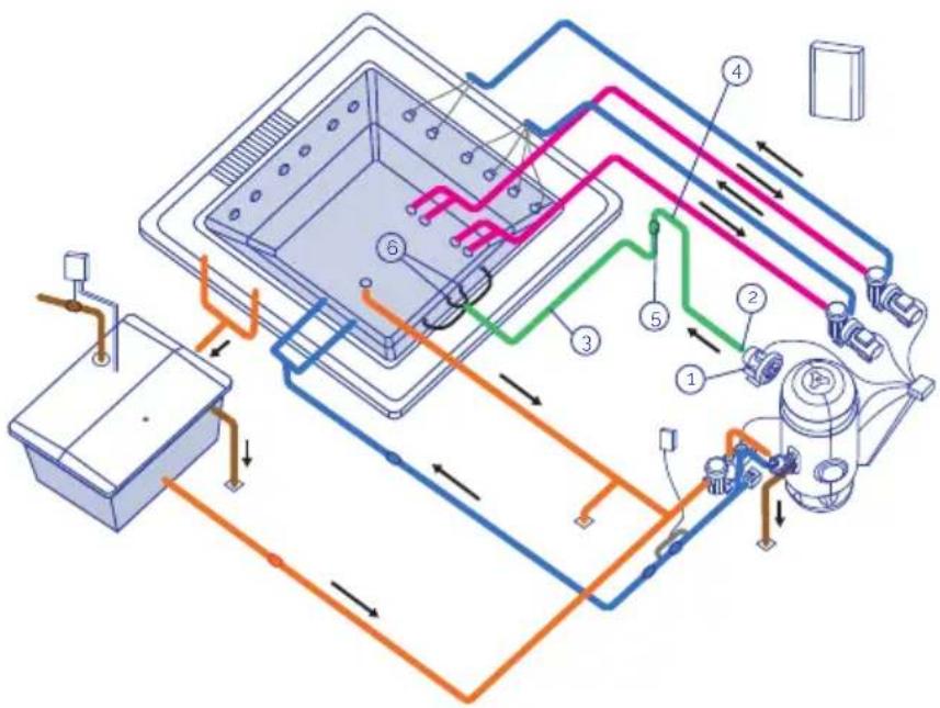
text_image
Technical schematic diagram of a device's internal components with numbered parts and directional arrows indicating flow or connection.1 Air suction
2 Blower pump
3 Air return circuit
4 Protection siphon
5 Check valve
6 Air injection nozzles
109
- BLOWER PUMP
Continued use blower pump for Compact Kit in public use installations. They operate with a 400 V AC III electrical supply as standard.
• AIR CIRCUIT
The mission of the air circuit is to return air from the blower pump to the Spa. The air is distributed inside the Spa via a series of blowing nozzles located on the floor or on the seats of the Spa.
3.3 Handling and locating the spa
- Handling of the Spa must be done very carefully and in a controlled manner by several persons.
• The Spa must never be hold by the pipes.
• The Spa should be installed following the criteria below. - No material should be used or located below the Spa and around it (in a minimum perimeter of one meter) unless it is completely resistant to humidity and water. The Spa warranty does not cover any damage to materials, decorative or ornamental objects that may deteriorate due to flooding or atmospheric humidity.
-
The Spa must be located in a duly adapted space which is adequate for withstanding significant damp and condensation. If this is not so, the warranty will not cover material or personal damages.
-
It is essential to have an adequately sized drain for draining out any water that could reach the area under the Spa.
- The base where the Spa will be installed should be large and strong enough to with stand the weight of the Spa, the water and the users. If this is not so, the warranty will not cover the damages caused. Check the building regulations in force.
- Prior to the installation, if you believe that for any reason you may have to extract the Spa from its initial location, you should take this factor into account, and avoid having to break down masonry or structures and pipes should the Spa have to be unassembled. The warranty does not include repair of any damages caused in this instance.
3.4. Advices to build foundations
Below we provide some basic advice as to how to build foundations for the Spa. It is essential to comply with building regulations in force in all cases.
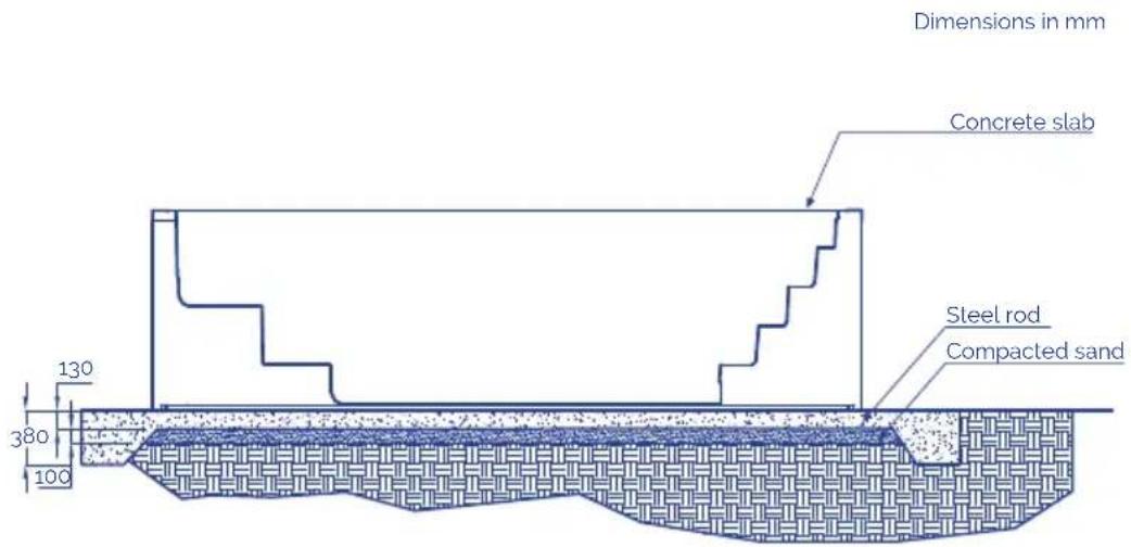
text_image
Dimensions in mm Concrete slab Steel rod Compacted sand 130 380 100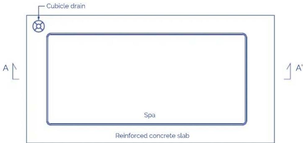
text_image
Cubicle drain A Spa Reinforced concrete slab A'* Equidistant reinforcement rods in both directions
The Spa is supplied with a metal structure to make installation easier. This structure has several support points.
Before filling up the Spa, these levelling points must be regulated so that all of them are in contact with the ground.
natural_image
Technical diagram of a structural support system with embedded concrete layers and grounding, showing no text or symbols.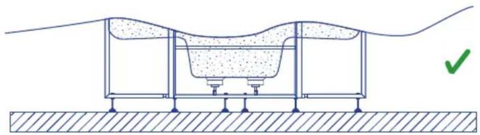
natural_image
Cross-sectional diagram of a mechanical or structural assembly with layered components and a green checkmark indicating a specific point (no text or symbols present)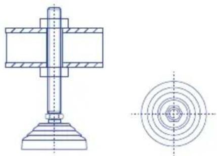
natural_image
Technical drawing of a mechanical assembly with cross-sectional and top views (no text or symbols)112
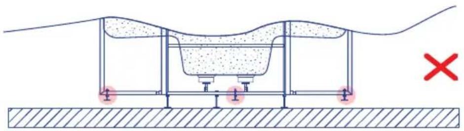
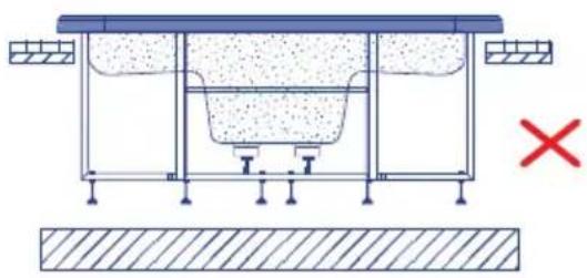
The Spa must be completely supported by the support structure, and must never be supported by its upper edge; otherwise the possible bending would cause the Spa shell to break.
natural_image
Technical diagram of a structural support system with embedded concrete and foundation, showing no text or symbols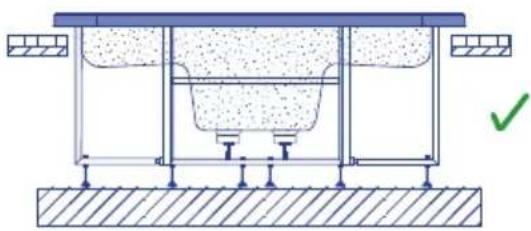
natural_image
Technical diagram of a structural support system with no visible text or symbols113
In order to seal the lip of the Spa to the foundations, use elastic silicone special forwater installations.
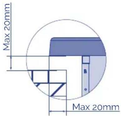
text_image
Max 20mm Max 20mm114
Once the Spa has been correctly fitted, finish the installation taking into account that you must leave a free passage of at least 400mm around the shell for possible maintenance works. Never place elements that may touch the body of the Spa, pipes or accessories in this area. Leave a trapdoor or accessway around the Spa for maintenance.
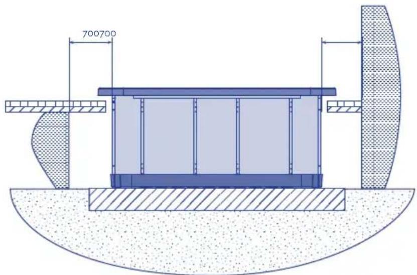
text_image
700700115
Never fill in the Spa's upper edge with cement or any other material that may have an expansion / contraction different to that of the Spa shell. The Spawould end up cracking. Never fill in with concrete the Spa's pipes or accessories.
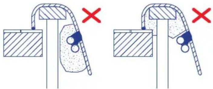
natural_image
Two identical diagrams showing a mechanical or structural assembly with cross marks, no text or symbols present.116
3.5. Electrical connections
Some advices to take into account before doing electrical connections:
- Pumps neutral wire remains free.
- Make sure the power supply is unconnected before starting the installation procedure.
- Respect indicated cable sections and distance between components.
To ensure a proper management of the electronic signals the distance between the components should not exceed the following:
Electronic push buttons - Electronic Board 15m
Spa-Hydraulic kit (Pumps) 7m
Balance Tank (Capacitive level sensors) - Electronic Board 15m
Heater (Temperature sensor) - Electronic Board 6m
Solenoid Valve - Electronic Board 20m
CONNECTION BETWEEN COMPACT KIT AND ELECTRIC CONTROL
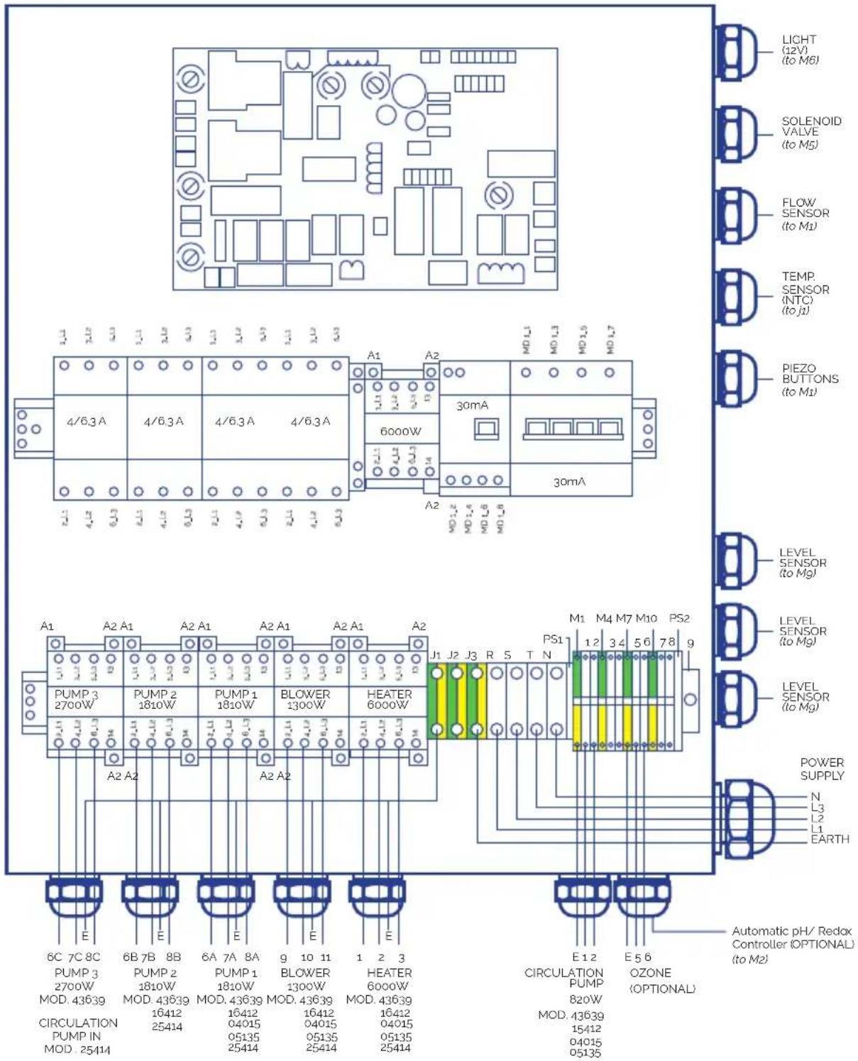
text_image
LIGHT (12V) (to M6) SOLENOID VALVE (to M5) FLOW/ SENSOR (to M1) TEMP. SENSOR (NTC) (to J1) PIEZO BUTTONS (to M1) 4/6.3A 4/6.3A 4/6.3A 4/6.3A 6000W 30mA 30mA A1 A2 MD L1 MD L3 MD L5 MD L7 4/6.3A 4/6.3A 4/6.3A 4/6.3A 6000W A2 MD L2 MD L4 MD L8 MD L9 LEVEL SENSOR (to Mg) PUMP 3 PUMP 2 PUMP 1 BLOWER HEATER 2700W 1810W 1810W 1300W 6000W J1 J2 J3 R S T N M1 M4 M7 M10 PS2 PS1 1 2 3 4 5 6 7 8 9 PUMP 3 PUMP 2 PUMP 1 BLOWER HEATER 2700W 1810W 1810W 1300W 6000W MOD. 43639 MOD. 43639 MOD. 43639 MOD. 43639 MOD. 43639 16412 16412 16412 16412 MOD. 43639 16412 MOD. 43639 16412 MOD. 43639 16412 MOD. 43639 16412 MOD. 43639 16412 MOD. 43639 16412 MOD. 43639 16412 MOD. 5135 MOD. 5135 MOD. 5135 MOD. 5135 MOD. 5135 MOD. 5135 MOD. 5135 MOD. 5135 MOD. 5135 MOD. 5135 MOD. 5135 MOD. 5135 MOD. 5135 MOD. M1 M4 M7 M10 PS2 POWER SUPPLY N L3 L2 L1 EARTH E E E E E E E E E E E E E E E E E E E E E E E E E E E E E E E E E E E E E E E E E E E E E E E E E E E E E E E E E E E E E E E E E E E E E E E E E E E E E E E E E E E E E E E E E E E Automatic pH/ Redax Controller (OPTIONAL) (to M2) CIRCULATION PUMP OZONE 820W (OPTIONAL) MOD. 43639 MOD. 43639 MOD. 43639 MOD. 43639 MOD. 43639 MOD. 43639 MOD. 43639 MOD. 43639 MOD. 43639 MOD. 43639 MOD. 43639 MOD. 43639 MOD. 43639 MOD. E I U D O Z O X Y Z Z Z Z Z Z Z Z Z Z Z Z Z Z Z Z Z Z Z Z Z Z Z Z Z Z Z Z Z Z Z Z Z Z Z Z Z Z Z Z Z Z Z Z Z Z Z Z Z Z Z Z Z Z Z Z Z Z Z Z Z Z Z Z Z Z Z Z Z Z Z Z Z Z Z Z Z Z Z Z Z Z Z Z Z Z Z Z Z Z Z Z Z Z Z Z Z Z Z ZWIRING SECTIONS
Connect cables to their corresponding sections to ensure proper functioning and to prevent potential electrical problems that could affect the user's safety.
P max [W]
| 20 > L [m] 20 ≤ L 35 [m] 35 ≤ L < 55 [m] | ||
| Sc [mm2] | 20 35 55 | |
| 0.5 882 504 321 | ||
| 1 1764 1008 641 | ||
| 1.5 2646 1512 962 | ||
| 2.5 4410 2520 1603 | ||
| 4 7055 4032 2566 | ||
| 6 10583 | 6047 3848 | |
| 10 17638 | 10079 | 6414 |
| 16 28221 | 16126 | 10262 |
KIT 43639
A
| Element | P total [W] | P phase [W] | I phase [A] |
| R | 6000 | 2000 | 9 |
| P.F | 820 | 273 | 1,6 |
| P.2 | 1810 | 603 | 3,2 |
| P.3 | 2700 | 900 | 3,2 |
| B | 1300 | 433 | 3,8 |
| PTC | - | - | - |
| F | - | - | - |
| T | - | - | - |
| T | - | - | - |
B
Sc [mm ^2 ]
| Element | P total [W] | P phase [W] | I phase [A] | 20 > L [m] | 20 ≤ L 35 [m] | 35 ≤ L < 55 [m] |
| T | - | - | - | 4 | 6 | 10 |
| N | - | - | - | 4 | 6 | 10 |
| L1-L2-L3 | 14463 | 4821 | 25.4 | 4 | 6 | 10 |
KIT 16412CE
A
| Element P | total[W] | P phase[W] | I phase[A] |
| R 6000 2000 9.0 | |||
| PF 820 820 3.8 | |||
| P1 1810 603 3.2 | |||
| P2 1810 603 3.2 | |||
| P3 0 0 0,0 | |||
| B 1300 433 3.8 | |||
| PTC --- | |||
| F --- | |||
| T --- |
B
Sc [mm²]
| Element | P total [W] | P phase [W] | I phase [A] | 20 > L [m] | 20 ≤ L 35 [m] | 35 ≤ L < 55 [m] |
| T-- | -46 | 10 | ||||
| N- | --46 | 10 | ||||
| L1-L2-L3 | 14463 | 4821 25.4 46 | 10 |
KIT 04015CE
A
| Element P | total[W] | P phase[W] | I phase[A] |
| R 6000 | 2000 9,0 | ||
| PF 600 | 600 2,7 | ||
| P1 1050 | 1050 4,9 | ||
| P2 0 0 0,0 | |||
| B | 1300 433 3,8 | ||
| PTC - | -- | ||
| F - | -- | ||
| T -- | - | ||
| T -- | - |
B
Sc [mm ^2 ]
| Element P | total[W] | P phase[W] | I phase[A] | 20 > L[m] | 20 ≤ L 35[m] | 35 ≤ L < 55[m] |
| T---2.5 | 46 | |||||
| N--- | 2.5 | 46 | ||||
| L1-L2-L3 | 9012 | 3483 | 17,7 | 2.5 | 4 | 6 |
A
| Element P | total[W] | P phase[W] | I phase[A] |
| R 6000 2000 9.0 | |||
| PF 820 820 3.8 | |||
| P1 1460 1460 6,8 | |||
| P2 0 0 0,0 | |||
| P3 0 0 0,0 | |||
| B 1300 433 3.8 | |||
| PTC --- | |||
| F | --- | ||
| T | --- |
B
Sc [mm²]
| Element | P total [W] | P phase [W] | I phase [A] | 20 > L [m] | 20 ≤ L 35 [m] | 35 ≤ L < 55 [m] |
| T | - | - | - | 2.5 | 4 | 10 |
| N | - | - | - | 2.5 | 4 | 10 |
| L1-L2-L3 | 9642 3893 | 19,6 2.5 4 | 10 | |||
HEATER CONNECTION
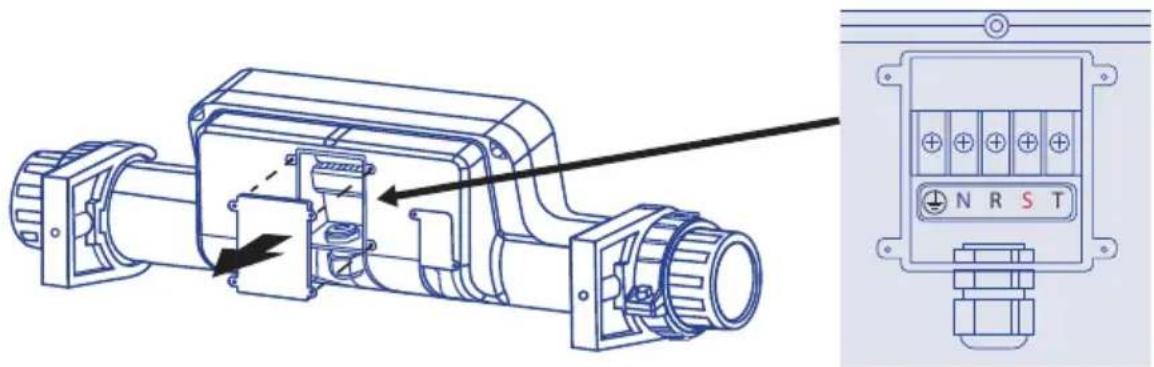
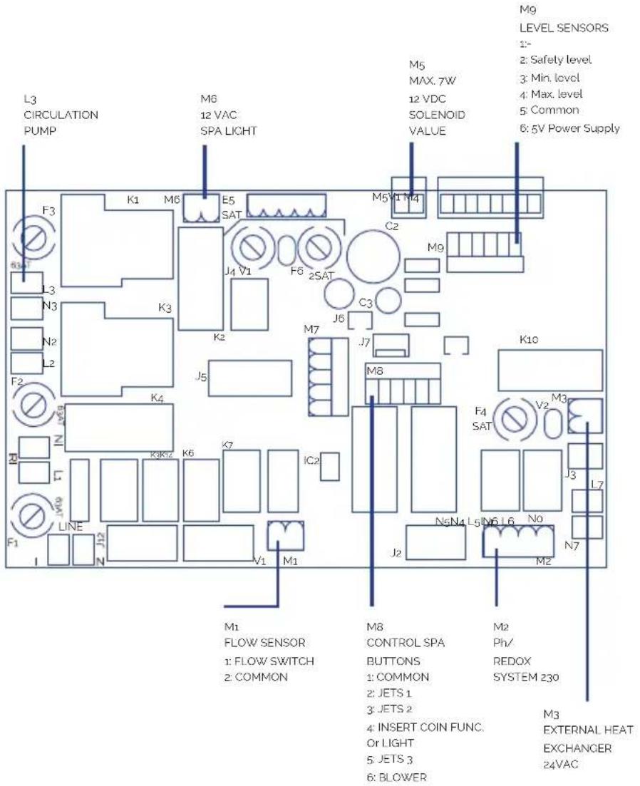
The connection of the PTC sensor must be made via an own channel in order to avoid possible interferences. Connect the Heater power supply to the electrical control board as follows:
- Open the rear housing of the Heater
- Connect the following outputs with the corresponding inputs of the electric control box.
• Neutral and Ground remain free:
text_image
Technical diagram of an electric motor assembly with labeled components and a close-up of its internal structure.PRINTED CIRCUIT BOARD
text_image
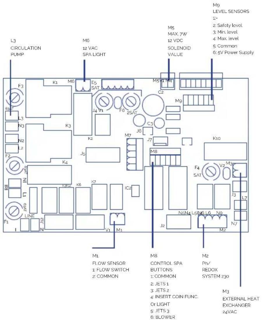
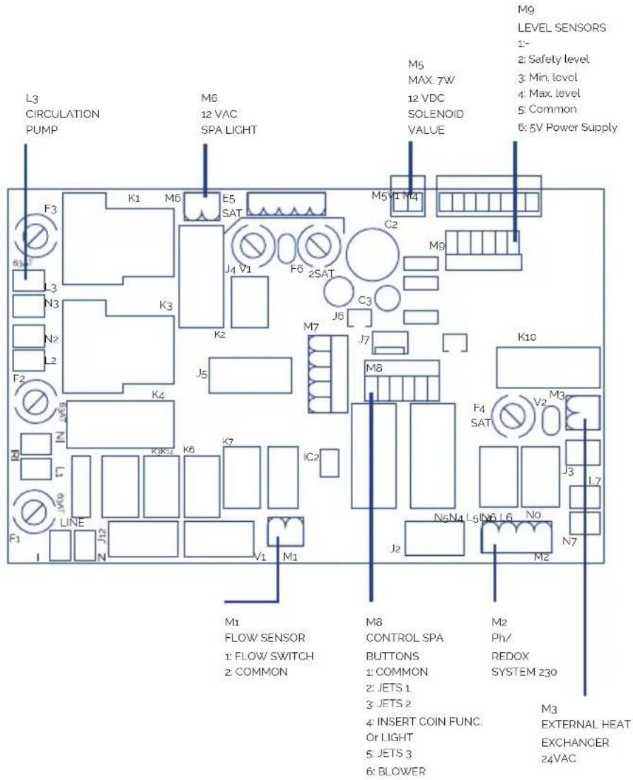
L3 CIRCULATION PUMP M6 12 VAC SPA LIGHT F3 K1 M6 E5 SAT J4 V1 F6 2SAT C2 M5 MAX. 7W 12 VDC SOLENOID VALUE M9 LEVEL SENSORS 1- 2: Safety level 3: Min. level 4: Max. level 5: Common 6: 5V Power Supply L3 N3 N2 L2 F2 K3 K4 J5 K10 IN M5 K3K2 K6 K7 IC2 F1 LINE J12 V1 M1 M1 FLOW SENSOR 1: FLOW SWITCH 2: COMMON M8 CONTROL SPA BUTTONS 1: COMMON 2: JETS 1 3: JETS 2 4: INSERT COIN FUNC. Or LIGHT 5: JETS 3 6: BLOWER M2 Ph/ REDOX SYSTEM 230 M3 EXTERNAL HEAT EXCHANGER 24VAC119
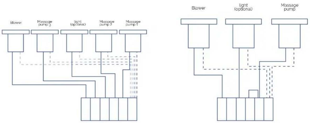
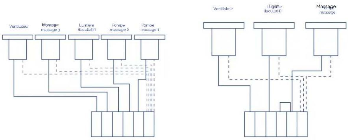
REMOTE SPA PUSH BUTTONS CONNECTION
flowchart
graph TD
    subgraph Left_Circuit
        A["Blower"] --> B["Massage pump 3"]
        B --> C["light (optional)"]
        C --> D["Massage pump 2"]
        D --> E["Massage pump 1"]
    end
    subgraph Right_Circuit
        F["Blower"] --> G["Light (optional)"]
        G --> H["Massage pump"]
    end
    style Left_Circuit fill:#f9f,stroke:#333
    style Right_Circuit fill:#bbf,stroke:#333
120
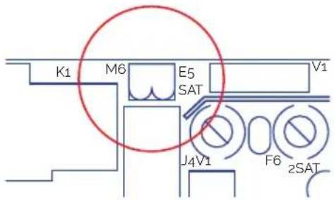
LIGHT
Connect directly to the M6 output of the PCB. Can be switched off or on from the front control panel of the electrical box.
text_image
K1 M6 E5 V1 SAT J4V1 F6 2SAT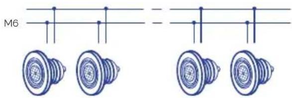
text_image
M6 =121
OTHER ELECTRICAL CONNECTIONS
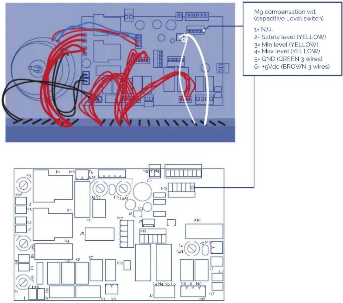
- Connect the three level sensors supplied with the balance tank directly to the Mg input of the PCB.
- Connect ozone wire directly to the grid 5-6 input of the electrical box.
- Connect the electric control box to the power supply.
! ATTENTION
Make sure all the hydraulic and electrical / electronical connections are done before connecting the electric control box to the power supply. It is mandatory to use packing glands for all the connections coming out of the cabinet and the junction box. It is mandatory to use terminals in all connections in order to preserve the integrity of the leads.
3.6. Hydraulic connection
KIT INSTALLATION
The compact kit must be below the Spa level. This avoids having to prime the pumps. The maximum difference in level is 2 metres below (h ≤2m).
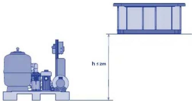
text_image
h ≤ 2mSpas with overflow have a balance tank, which has a double function:
- Absorbing the water displaced by the people who enter the Spa.
- Ensuring the filtration pump is never left without water.
To correctly install this tank, it should be placed as near as possible to the Spa, below the level of the overflow, so that the overflow can evacuate all the water.
KIT TO SPA CONNECTION
Use a hard pipe or flexible hose of an appropriate resistance. Check the regulations in force in each country.
You must use the same pipe diameter as that of the Spa's connection; these diameters are sized for optimal performance of the kit. Use the right glue for each material. In any case, it will be necessary to minimize the installation of elbow fittings and pipe length to reduce the drop of pressure in the installation.
The Spa's connections with couplings are marked with stickers indicating the circuit and the water flow direction.
Before and after each pump and on the heat exchanger outlet, place a ball or guillotine valve for carrying out maintenance or replacements on these elements.
RECIRCULATING CIRCUIT CONNECTION
SPA WITH OVERFLOW
Spa Connection - Balance Tank
Connect the overflow pipes to the balance tank. The pipes should be sloping sufficiently to ensure the water evacuates by gravity. Under no circumstance should siphons be created that could prevent water circulation. The diameter of the pipes for collecting water from the overflow should be calculated in such a way that the water does not exceed the recommended speed by the regulations in force. Connect a drainpipe in the upper part of the balance tank; its function is to evacuate possible excess water preventing the deposit from overflowing. Connect the balance tank outlet with the filter pump suction, placing a check valve between the deposit and the pump.
The outlet will have to be placed below or at the same level as the bottom of the balance tank. Spa with overflow
Connection between Balance Tank – Compact Kit
Connect the filter pump outlet to the filter's selector valve (depending on the kit model, this connection may already been made). Connect the selector valve outlet with the water inlet of the heat exchanger (depending on the kit model this connection may already be made). If your Spa has the ozone option, follow the instructions indicated in the Ozoniser installation sheet now.
For the selector valve connections, always use plastic accessories, gasket and Teflon
tape. Under no circumstance should you use metal accessories or tubing, which could seriously damage the plastic components.
Connection between Spa - Compact Kit
If your spa has a spa oor cleaning connection; connect the oor cleaning outlet with the lter pump inlet making the connection in parallel with the other inlets to this pump. You must place a ball valve between the outlet and the pump which will normally remain closed.
• Option A Spa Floor Suction: Connect the Spa oor drain to an inlet in parallel to the lter pump. Place a ball or guillotine valve between this connections.
- Option B Spa Floor Return: No operation is required.
Connection between Compact Kit - Spa
Connect the heat exchanger with the Spa lter return sleeves.
• Option A Spa Floor Suction: Place a check valve between the exchanger outlet and the inlet to the spa.
• Option B Spa Floor Return: Connect the exchanger outlet with the Spa oor drain, in parallel with the iter return via the return nozzles .
Installation of level sensors
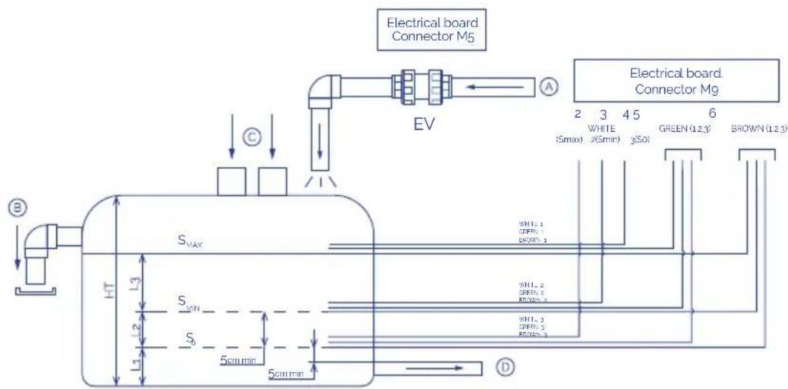
In order to ensure that the recirculating circuit always contains water, you must install the level senors in the balance tank. These will control the opening and closing of a lling solenoid valve.
Look at the following diagram.
flowchart
graph TD
    A["Electrical board. Connector M5"] --> B["EV"]
    B --> C["Electrical board. Connector M9"]
    D["S_VAX"] --> E["HT"]
    D --> F["S_VIN"]
    D --> G["S"]
    D --> H["5cm min"]
    D --> I["5cm min"]
    J["2 3 4 5 6"] --> K["White (Smax 2Gmin) 3So1 GREEN(12.3) BROWN(12.3)"]
    K --> L["White 1 OFFR 1 BROWN 1"]
    K --> M["White 2 GREEN 2 BROWN 2"]
    K --> N["White 3 OFFR 3 BROWN 3"]
    O["A"] --> P["→"]
    Q["C"] --> R["→"]
    S["D"] --> T["→"]
So Safety probe
SMIN Minimum level probe
SMAX Maximum level probe
EL Electric control box
EV Electric valve (not included)
A Network water inlet
B Deposit overflow
C Spa overflow water inlet
D Water outlet towards filtration
Ht Total height
So sensor has to be placed above the bottom outlet pipe.
Smin sensor has to be placed above So sensor.
There must be more water than the volume displaced by all bathers between Smin and Smax. Smax has to be placed below the top drain..
The level sensors have to be attached to outer side of the balance tank.
The system will be automatically blocked when water level is below so sensor.
The electric valve (EV) will be activated (the tank will start filling) when the level drops to below SMIN and will be deactivated when it exceeds SMAX.
If you do not install level sensors, follow the next diagram.
text_image
Mg compensation vat (capacitive Level switch) 1= N.U. 2= Safety level (YELLOW) 3= Min level (YELLOW) 4= Max level (YELLOW) 5= GND (GREEN 3 wires) 6= +5Vdc (BROWN 3 wires)SPA WITH SKIMMER
Connection Spa - Compact Kit
- Connect the skimmer outlet with the heat exchanger inlet.
- Connect the Spa floor drain with the filtration pump inlet in parallel to the rest of the inlets.
- Connect the filtration pump outlet to the filter's selector valve (depending on the kit model, this connection may already be made).
- Connect the selector valve outlet to the water inlet of the heat exchanger (depending on the kit model, this connection may already be made).
If your Spa has the ozone option, follow the instructions indicated in the Ozonator installation sheet now.
For the selector valve connections, always use plastic accessories, gasket and Teflon tape. Under no circumstance should you use metal accessories or tubing, which could seriously damage the plastic components.
Connection Compact Kit- Spa
Connect the heat exchanger outlet with the Spa's filter return nozzles, placing a check valve in this connection.
Water massage circuit connection
Connect the pipe to the water suction drains with the inlet to the massage pump (each pump will suction the water of 2 drains). Connect the outlet of each of the massage pumps to the connections in the Spa battery that will guide the water to the jets. Place a ball or guillotine valve in the inlet and outlet of each pump.
Air massage circuit connection
Leave the air pump inlet free and connect the pump outlet to the Spa's corresponding connection.
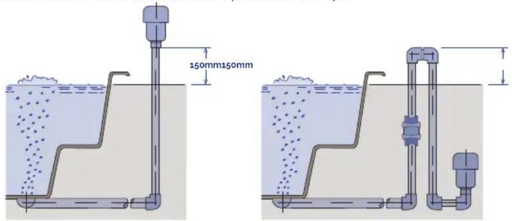
Note: It is essential to install a 150mm siphon above the maximum water level and to place a check valve between the siphon and the Spa.
text_image
150mm150mm4. START UP
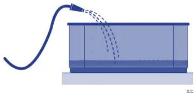
With the main circuit breaker on the OFF position, clean the Spa shell to avoid particles of the works being absorbed and obstructing the components or circuits.
Open all the valves except the drainage.
- SPAS WITH OVERFLOW AND BALANCETANK
Open the Spa's filling valve and fill up the Spa until the water exceeds the SMAX level of the balance tank by 5 to 8 cm.
Important: When you start up the filtering equipment for the first time, the water level of the balance tank will decrease substantially. This is due to the fact that the piping between the balance tank and the Spa, filter and pump is practically full of air.
• SPAS WITH SKIMMER
Wait for 15 minutes and inspect all the connections to ensure there are no leaks. Provide electrical power to the cabinet by switching on its main circuit breaker (ONposition). Start up the filter pump, the massage pump and the air pump and check that there are no leaks in the pipes and connection elements after 30 minutes of operation.
Stop the filter pump and fill the water filter up to half, and then subsequently fill with sand (the type of sand to be used is specified in the Filter Manual annexed to the Compact Kit).
Place the selector valve of the filter with the lever in the wash position. Manually activate the filter pump; carry out a wash in the filter lasting approximately 2 minutes, stop the pump and set the lever to the rinse position. Start up the pump again and rinse for approximately 15 seconds.
Stop the pump and change the lever to the filter position. Fill up the Spa once again. Program the thermostat to the desired temperature. Read the Compact Kit manual. (Reaching the desired temperature after filling up the Spa may take several hours). Program the filter clock. (Read the Compact Kit Manual).
In the main electrical cabinet, activate the massage and heating switches. Set the filtering switch to the desired position, and the Spa will start to function carrying out the filtering and heating cycle. Once these checks have been made, fill in the attached Warranty form and send it to the manufacturer.
Jets can also regulate the intensity of the flow by opening and closing the water flow. To do so, proceed as follows:
126
Spas are built to the highest standards with the most durable materials available. The right maintenance and care will be key factors to ensure your Spa and its components have a long life.
5. OPERATING INSTRUCTIONS
5.1. Warnings
SAFETY WARNINGS
- Carefully check the water temperature. Do not use the water at temperatures over 40^ . Ideal temperature is 35 - 36^ .
- Pregnant women, small children, persons with heart conditions, or health problems or under medical care must not use the spa without first consulting a doctor.
• Take special care if you are alone when using the spa. Prolonged immersion in warm water may cause nausea, dizziness and fainting. - Set the spa at a lower temperature if you intend to use the spa for more than 10-15 minutes.
- Do not use the spa after drinking alcohol, taking drugs or medicines that cause drowsiness or that can raise/lower the blood pressure.
- Be especially careful when getting in and out of the spa when the floor is wet.
- Electrical appliances (radios, hair dryers etc.) must not be used near the spa.
- During use of the spa, keep your head, body and clothes at a distance of at least 40 cm from the suction intakes. Long hair must be tied back and secured in place.
- Do not start the spa if the protective grilles are broken or missing.
- Only use original spare parts. Any modification requires manufacturer authorisation.
- Check the level off free chlorine and pH before use. Do not use the spa if these levels are out of normal recommended ranges or if a shock treatment is in process.
USE WARNINGS
Power supply interruption
Should the power supply be interrupted, the system will always automatically restart in the operating mode it was in before the interruption.
After a power outage the filtration pump will automatically start. Make sure the hydraulic circuit is ready or connect/disconnect necessary items before starting the system.
Incompatible functions
In order to prevent possible interferences between functions the system software doesn't allow the following operations:
- When the filtration pump has been activated in manual mode it must also be manually deactivated before switching on any other pump, or the system will stop and E02 (error 02) will be shown in the main display. Push SET and MANUAL keys consecutively to deactivate the error message.
- All pumps must be switched off before switching from manual to automatic mode, or the system will stop and E02 (error 02) will be shown in the main display. Push SET and MANUAL keys consecutively to deactivate the error message.
- The filtration pump is always activated for the first 5 minutes after the system starts, and continues working until the programmed temperature is reached. The heater then shuts off and the filtration pump continues working for 5 more minutes in order to cool the heater to atmospheric temperature.
- The insert coin feature (optional) is not compatible with the light control via external button option.
RISK OF HYPERTHERMIA
- Prolonged direct contact with hot water can cause HYPERTHERMIA, which occurs when the internal temperature of our body reaches levels above the normal temperature of 36.5^ .
- Symptoms of hyperthermia include a sudden drop in blood pressure and in consequence a feeling of faintness with the possibility of fainting.
• The Spawater should never exceed 40°C. - Water temperatures of between 37^ and 40^ are considered safe for adults who have no health problems. Lower temperatures are recommended for most people and for children.
- Remember that prolonged bathing in the Spa can cause hyperthermia.
• The use of alcohol, drugs or medication may increase the risk of hyperthermia.
5.2. Remote control (Spa buttons)
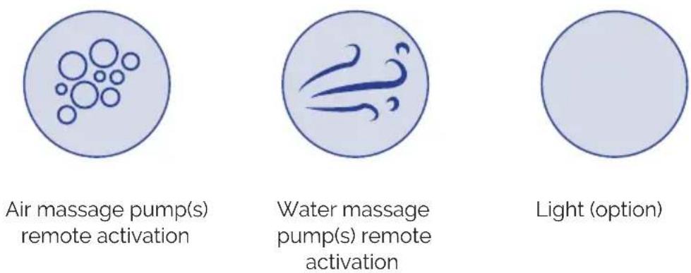
The pumps can be activated from the spa if the appropriate switches are installed. Each switch can control one or more pumps at once. Depending on the system's configuration.
- By pressing the corresponding switch the pump begins to operate and does not stop until the time programmed in parameter d1 (Units and Massage Setting Menu) is completed or the switch is pressed again.
- If the parameter d2 has been programmed with a value greater than 0 the pump may not be activated until this time has elapsed.
- Massage and inhibition time are independent for each switch.
6. MAINTENANCE
6.1. Maintenance warnings
- Before proceeding to carry out any electrical or mechanical intervention, please ensure the machine is disconnected from the power supply network and that the start up devices are blocked.
- Do not handle the equipment with wet feet.
6.2. Acrylic maintenance
Easy care for an elegant surface:
- Use common cleaners for general use. For normal care and cleaning, use a soft cloth or sponge with a little soap and water. Rinse it well, and dry with a clean, dry cloth. If you are using a household cleaner, please ensure it is recommended for acrylic surfaces by the manufacturer.
- Never use abrasive cleaners.
- Do not allow the acrylic surface to come into contact with ketones or esters such as acetone, acetates (such as nail varnish remover, nail varnish or dry cleaning substances) or any organic solvent with chlorine, varnishes, petrol, aromatic solvents, etc.
- Remove dust, smears and dry dirt with a soft, moist cloth.
- Clean off grease, oil, paint and ink stains with isopropyl alcohol and dry it with a clean, dry cloth.
- Avoid using razors or any other kind of sharp instrument that could scratch the surface. Small scratches can be removed by applying a fine layer of automotive varnish and lightly polishing it with a clean cloth.
Once a week, clean the area of the Spa which is not underwater with a quality polish for Spas.
! ATTENTION
Remember to never leave the Spa uncovered, empty and exposed to the sun, as it could cause damages that the warranty does not cover.
6.3. Maintenance in periods of non-use or absence
SHORT PERIODS (3-5 days)
- Adjust the pH and treat the water (see Water Maintenance section).
- Cover the spa.
- Before using the Spa again, readjust the pH and treat the water again.
PROLONGED PERIODS (5-14 days)
- Set the temperature at its lowest level.
- Adjust the pH and treat the water (see Water Maintenance section).
- Cover the Spa.
- Before using the Spa again, reset the temperature as required, readjust the pH and treat the water again.
PREPARTING FOR THE WINTER PERIOD
If it is not planned to use the Spa through the winter season or for prolonged periods of time, the following operations should be done:
- Disconnect the electrical equipment.
• Empty the water from the Spa. - Leave the drain valve open.
- Clean and dry the Spa.
- Cover the Spa.
You should not leave water in the Spa without an electrical connection outdoors in temperatures below 0^ C, given that the pipes could freeze and damage the Spa.
It is necessary to comply with Regulations in force in each country regarding Legionella. All responsibility for compliance with these falls on the owner of the Spa.
6.4. Water maintenance
Water maintenance is one of the areas where the user should provide greatest attention, given its importance. This maintenance will depend on the mineral content of the water used, of the Spa's frequency of use, and of the number of people using the Spa.
There are three main points to take into account inwater maintenance:
• WATER FILTRATION
• CHEMICAL ANALYSIS AND PH CONTROL
• DISINFECTION OF THE WATER
SAFETY IN USE OF CHEMICAL PRODUCTS
Before using any chemical product, carefully read the instructions for use on its product label.
- It is advisable that always the same person handles the chemical products. Keep these products away from children.
- Add the exact amounts to the water, as specified.
- Keep containers tightly closed in dry, well-ventilated places.
-
Do not inhale chemical products, and take care not to let them come into contact with the eyes, nose or mouth. Wash hands after use.
-
Follow the emergency instructions on the product label in the event of an accident or ingestion.
- Do not smoke while handling these products – they may be flammable.
- Do not store these products inside the Spa unit.
- Do not mix products. Add first one and then the other to the water, to avoid possible reactions.
- Do not add chemical products to the water if there is someone in the Spa.
PH ADJUSTMENT
A pH index of between 7.2 and 7.6 is recommended.
The pH level measures the acidity and alkalinity: Values above 7 are alkali and below 7, are acid.
! ATTENTION
It is very important to maintain the correct pH level both for the disinfectant to work properly and to prevent corrosion or deposits on the Spa. Any damage caused by an inadequate pH level is not covered by your Spa guarantee.
If the level of pH is very low, the effects are as follows:
• The disinfectant will dissolve rapidly.
• The Spa kit may start to show corrosion.
- The water may start to produce irritation in bathers.
If the level of pH is very high, the effects are as follows:
• The disinfectant is less effective.
- The acrylic and the kit may start to showscaling.
• The water may turn cloudy.
- The filter cartridge pores may be obstructed.
Check the pH of the water with the pH analyser case on a daily basis.
If the pH is above these indexes, use pH MINOR SPA. Wait for two hours before doing the pH test. When the pH index has been adjusted to the values indicated above, proceed to the next step.
WATER DESINFECTION
Disinfecting the water is of utmost importance in order to destroy algae, bacteria and any other organisms that may grow in the water. However, excessive disinfection can cause irritations to the skin and eyes.
The appropriate disinfectant for your Spa water is BROMINE TABLETS. Place this product in the pre-filter for it to gradually dissolve.
Check the level of residual bromine using the Br analyser case on a daily basis.
Residual bromine levels of between 2.2 and 3.3 ppm are recommended.
Should you use Chlorine, in order for it to be effective, you must maintain a concentration of Free Residual Chlorine of between 0.5 and 1.5 ppm.
USE OF SPECIAL PRODUCTS
In addition to products for maintaining pH and disinfectant levels, there are others especially designed for use in Spas which will help you to maintain the water and the installations in perfect conditions.
• TIMESCALE REMOVER FOR SPAS: Avoids the formation of calcium salts (scaling), especially in hard water. This product is added weekly and every time the water is renewed.
- ALGAECIDE FOR SPAS: This algaecide prevents the growth of algae in the Spa water. The product is added weekly and every time the water is renewed.
- FOAM REMOVER FOR SPAS: Due to the agitation of the water and the grease present in it, foam often forms in Spas. When ever you notice a significant amount of foam in the water, you can eliminate it with this product.
- GREASE REMOVER FOR SPAS: For eliminating the rings of dirt and grease that form on the walls of the Spa. To use this product we advise emptying the water from the Spa, and applying the grease remover with a sponge on the areas to be cleaned. Then rinse immediately with abundantwater.
OZONE GENERATOR
Ozone, O3, is an oxidising chemical component which is very effective in disinfecting water. Its main advantage is that it leaves no chemical residue and is odourless.
Its disinfectant properties are based on its oxidising potential, which leads to the elimination of any organic matter that there may be in the water.
In order to produce ozone, some Spas have an ozonator which, with electricity, can produce ions of ozone from atmospheric oxygen. This process occurs automatically, and the product generated is injected via the filtration return nozzles. Thus, it is not necessary for the user to activate any mechanism for its generation.
The water is collected by the overflow, the drains or the skimmer, due to the suction of the filter pump.
Then it passes through the heat exchanger and in its outlet it is injected with ozone. The water is distributed via the filtration return system.
Ozone treatment does not exclude the use of other chemical products such as Bromine or Chlorine.
The ozone is considered as a complementary process to the ones above, thus reducing the consumption of Bromine or Chlorine.
QUICK GUIDE FOR CHEMICAL PRODUCT APPLICATION
| Reason for use Amounts per m of water | 3 | Frequency of use | |
| PH MINOR SPA Add | if the pH test comes out above recommended values (7.2-7.6 ppm). | Add according to recommendations of the chemical product manufacturer. | Analyse the pH daily with the pH Test. |
| PH MAJOR SPA Add | if the pH test is below recommended values (7.2-7.6 ppm). | Add according to recommendations of the chemical product manufacturer. | Analyse the pH daily with the pH Test. |
| BROMINE TABLETS Add | if the Br test is above recommended values (3-5 ppm). | Add according to recommendations of the chemical product manufacturer. | Analyse the Br daily with the Br. Test. |
| LIME SCALE REMOVER | Avoid the formation of calcium salts (scaling). | Add according to recommendations of the chemical product manufacturer. | Once per week, and each time the water is renewed. |
| ALGAECIDE FOR SPAS | Prevents the growth of algae in the water. | Add according to recommendations of the chemical product manufacturer. | Once per week, and each time the water is renewed. |
| SE REMOVER Eliminate rings of dirt on the Spa walls. | Scrub with a sponge and immediately rinse with abundant water. | Whenever dirt is observed on the Spa walls. | |
| FOAM REMOVER Presence of foam in water. Add according to recommendations of the chemical product manufacturer. | Whenever foam appear in the water. | ||
7. ERROR CODES
The following table summarize the errors codes the display shows to the operator and the related description.
| Type | Description Cause Solution | ||
| E01 | Safety level of balance tank not reached. Autoresettable. | The Safety level sensor of the balance tank doesn't detect water. No function can be activated. | Fill the balance tank until minimum sensor level. |
| E02 | Water flow or temperature failure. Automatically self-operational alarmAutoresettable. | Flow sensor doesn't detect water flow or temperaturesensor doesn't send any signal. No function can be activated. | Check possible obstructions in the filtering circuit, pumps, or filter. Check possible sensor malfunction. |
| E04 | Water temperature is too high. Automatically self-operational alarm Autoresettable. | The water temperature inside the Spa is over 42°C. No function can be activated. | Let the water cool or add cool water. When the temperature will be below 42°C your SPA will start up automatically; if not unplug the power supply and contact your dealer. |
| E05 | Water temperature sensor. Autoresettable. | The temperature sensor is malfunctioning. No function can be activated. | Check the water temperature and temperature sensor and replace it if needed. |
| E07 | Heater contactors. Not Autoresettable. | The heater contactors are malfunctioning; you cannot activate the electrical heater. | For safety reasons, the electric heater is powered by two contactors, which are serially connected; if one of these two contactors is stuck, an error message will appear. Replace corresponding contactors and plug the elements again. |
| E08 | |||
| E09 Max. | time of the balance tank water filling exceeded. Not Autoresettable. | The max opening time (30') of the loading electrovalve of the balance tank has been reached | Make sure that the sensors of water level of the balance tank work properlyMake sure that the discharge hole has been left open.Check a possible water leakage in the hydraulic circuit. |
| E10 | Balance Tank Water levels signals are incompatibles. Autoresettable. | Water level sensors are sending incompatible signals. | Check position of the level sensors or replace them if they are malfunctioning. |
| E11 | Water level in the balance tank is below safety sensor. Autoresettable. | Some function is trying to be activated before the minimum level inside the balance tank has been reached (or when working, the level is below the safety sensor). | Make sure that the loading electrovalve is open and works properly. Make sure there's no obstruction in the water charging circuit. Verify there's no water leakage in the hydraulic circuit. |
| E0 | Communication between Panel Control Board and local keypad. | Communication between Panel Control Board and local keypad is lost. | Make sure that the cable between the local keypad and the Panel Control Board is connected properly. If it is, unplug the system from the mains and get in touch with your dealer. |
- PROBLEMS AND SOLUTIONS
* Only in the case of pneumatic push buttons.
| Problem Reason Solution | ||
| No element is activated. Circuit breaker on OFF position. Switch circuit breaker to ON. | ||
| No pump or heating is activated. Operating switch in OFF position. Change operating switch to ON. | ||
| FILTER | ||
| Low water flow during filtration. Obstructed or dirty filter. Wash filter. | ||
| Filter pump is not activated. Filter pump faulty. Check pump / Change brushes. | ||
| Pump selector on stop. Change to manual or automatic. | ||
| WATER MASSAGE | ||
| Massage pump is not activated. | Signal transmission cable disconnected. | Conectar el tubito' / cable. |
| Air bulb in push button damaged.* | Change bulb.* | |
| Faulty pump. | Check pump / Change brushes. | |
| Faulty or poorly connected ontactor. | Installer: Check connection cables. Change contactor. | |
| Poorly regulated thermal magnetic breaker. | Adjust thermal magnetic breaker according to motor consumption. | |
| Faulty thermal magnetic breaker. | Change thermal magnetic breaker. | |
| Faulty thermal magnetic breaker. | Change thermal magnetic breaker. | |
| General massage switch on OFF. | Set switch to ON. | |
| Low air flow in jets. Water comes out the Venturi jet. | Closed and obstructed venturis. | Open Venturis. |
| Eliminate obstructions | ||
| Incorrectly placed jet front | Check jets | |
| AIR MASSAGE | ||
| The massage pump is not activated. | Signal transmission wire disconnected. | Connect the cable. |
| Air bulb in push button damaged.* | Change bulb.* | |
| Faulty pump. | Check the pump / Change brushes. | |
| Faulty or poorly connected contactor. Installer: Check connection wires. Change contactor. | ||
| Badly regulated thermal magnetic breaker. | Adjust thermal magnetic breaker according to motor consumption. | |
| Faulty thermal magnetic breaker. Change thermal magnetic breaker. | ||
| General massage switch on OFF. | Change switch position to ON. | |
| HEAT EXCHANGER | ||
| The thermostat does not indicate the correct temperature. | Poorly fitted temperature probe. Fit the probe properly into its housing. | |
| Faulty temperature probe. Change the probe. | ||
| Temperature controller damaged. Change controller. | ||
| No hot water. Heat exchanger | ber badly wired / defective. Check wiring resistance /Change Heat exchanger. | |
| Contactor damaged or bad connection. Installer: Check wiring connection.Replace contactor. | ||
| Magneto - thermal damaged. Change magneto -thermal. | ||
| Exchanger switch OFF. Turn switch to ON. | ||
| Flow switch bad wired / damaged. Check wiring flow-switch /Change flow switch. | ||
| Safety thermostat detect T>65°C. Reset safety thermostat | ||
9. RECYCLING AND ENVIRONMENT
Your Spa contains electrical and/or electronic material. When it reaches the end of its useful life, it must be treated as specialwaste.
Contact your local authorities to find out about the procedure for collecting and treating waste containing electrical and electronic material.

301
10. EVIDENCE OF CONFORMITY

IBERSPA, S.L.
N-II km 516,8
Carrer Projecte II
25200 - Cervera (Lleida)
SPAIN
ES PRODUCTOS: DA PRODUKTER:
EN PRODUCTS: S PRODUKTER:
DE PRODUKTE: A TOUTTEET:
FR PRODUITS: N PRODUKTER:
IT PRODOTTI: GR II PIONTA:
PT PRODUTOS:
NL PRODUKTEN:
RU продукт:
SPAS PÚBLICOS Y KITS
COMPACTOS
PUBLIC SPAS AND COMPACT
KITS
EN - EVIDENCE OF CONFORMITY
The products listed above are in compliance with :
2014/30/EU (Electromagnetic Compatibility), Directive 2014/35/EU (Low Voltage) and with the European Standard EN 60335-2 -41.
FR - DECLARATION CONFORMITÉ
Signature/Qualification :
Signature/Qualification :
Firma/Qualifica :
Assinatura/Título :
Manager of Iberspa, S.L. by proxy
E-206-07/01/2020
! ATENCIÓN
text_image
Technical diagram of a refrigeration unit with numbered components and airflow pathstext_image
Technical diagram of a device with numbered components and directional arrows indicating flow or assembly.text_image
Technical schematic diagram of a device with numbered components and colored flow paths indicating process flow.1 Desbordante
2 Tomas del desbordar
text_image
Technical diagram of a device's internal components with numbered parts and colored wiring pathstext_image
Technical diagram of a mechanical or electrical device with numbered components and directional arrows indicating flow or movement.natural_image
Technical line drawing of a mechanical pump or motor assembly (no text or symbols)106
natural_image
Technical line drawing of a mechanical assembly with cylindrical components and mounting brackets (no text or symbols)207
• FILTRO
text_image
Technical schematic diagram of a device's internal components with numbered parts and directional flow arrowstext_image
Technical schematic diagram of a mechanical or electrical system with numbered components and directional flow arrowsnatural_image
Technical diagram of a structural support frame with embedded concrete and ground level, showing no text or symbols.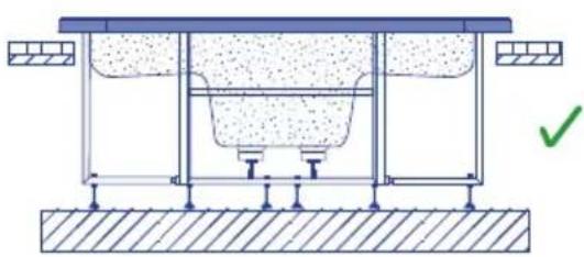
natural_image
Technical diagram of a structural support system with no visible text or symbols113
natural_image
Two identical diagrams showing a mechanical or structural setup with cross marks, no text or symbols present.116
| Elemento P total [W] | P fase [W] | I fase [A] | 20 > L [m] | 20 ≤ L 35 [m] | 35 ≤ L < 55 [m] |
| T --- 2.5 | 46 | ||||
| N --- | 2.5 | 46 | |||
| L1-L2-L3 | 9012 | 3483 | 17.7 | 2.5 | 4 |
A
| Elemento P total [W] | P fase [W] | I fase [A] |
| R 6000 2000 9.0 | ||
| PF 820 820 3.8 | ||
| P1 1460 1460 6,8 | ||
| P2 0 0 0,0 | ||
| P3 0 0 0,0 | ||
| B 1300 433 3.8 | ||
| PTC --- | ||
| F | --- | |
| T | --- |
B
Sc [mm²]
| Elemento | P total [W] | P fase [W] | I fase [A] | 20 > L [m] | 20 ≤ L 35 [m] | 35 ≤ L < 55 [m] |
| T | - | - | - | 2.5 | 4 | 10 |
| N | - | - | - | 2.5 | 4 | 10 |
| L1-L2-L3 | 9642 3893 | 19,6 2,5 4 | 10 | |||
text_image
Technical diagram of an electric motor assembly with labeled components and a close-up view of the main motor terminal.PLACA DE CIRCUITO IMPRESO
text_image
L3 CIRCULATION PUMP M6 12 VAC SPA LIGHT M5 MAX. 7W 12 VDC SOLENOID VALUE M9 LEVEL SENSORS 1: 2: Safety level 3: Min. level 4: Max. level 5: Common 6: 5V Power Supply F3 K1 M6 E5 SAT J4 V1 F6 2SAT C2 M5V1 M4 C3 M9 L3 N3 K3 K2 J6 M7 J7 K10 IN V89 K4 K3K12 K6 K7 IC2 F2 D1 LINE I N J2 V1 M1 M1 FLOW SENSOR 1: FLOW SWITCH 2: COMMON M8 CONTROL SPA BUTTONS 1: COMMON 2: JETS 1 3: JETS 2 4: INSERT COIN FUNC. Or LIGHT 5: JETS 3 6: BLOWER M2 Ph/ REDOX SYSTEM 230 M3 EXTERNAL HEAT EXCHANGER 24VAC119
natural_image
Technical diagram of a mechanical system with a height dimension labeled h ≤ 2m (no text or symbols beyond the label)122
text_image
150mm150mm125
4. PUESTA EN MARCHA
natural_image
Abstract graphic with a blue circular shape and a black upward arrow, no text or symbols present.natural_image
Simple diagram of circles inside a circle, no text or symbols presentnatural_image
Abstract circular logo with stylized wave or flame-like elements (no text or symbols)natural_image
Simple circular shape with no text, numbers, or symbolsLuz (opcional)
127
6. MANTENIMIENTO
natural_image
Two symbols: a recycling symbol and a waste bin with an X-bracing (no text or labels)EN PRODUCTS: S PRODUKTER:
DE PRODUKTE: FI TOUTTEET:
FR PRODUITS: N PRODUKTER:
IT PRODOTTI: GR PIONTA:
PT PRODUTOS:
NL PRODUKTEN:
RU продукт:
SPAS PÚBLICOS Y KITS
COMPACTOS
PUBLIC SPAS AND COMPACT
KITS
EN - EVIDENCE OF CONFORMITY
The products listed above are in compliance with :
2014/30/EU (Electromagnetic Compatibility), Directive 2014/35/EU (Low
Voltage) and with the European Standard EN 60335-2-41.
S - OVERENSSTEMMELESESERKL∅RING
OvenstΣende produkter oppfyller betingelsene elektromagnetiskdirektiv
2014/30/EU, lavpenningsdirektiv 2014/35/EU, og Europeisk Standard EN
60335-2-41.
FR - DECLARATION CONFORMITÉ
Signature/Qualification: Underskrft/Stilling:
Manager of Iberspa, S.L. by proxy
E-206-07/01/2020
! ATTENTION
text_image
Technical diagram of a multi-level electrical or mechanical system with numbered components and directional flow arrows indicating connections.text_image
Technical diagram of a mechanical or electrical device with numbered components and directional arrows indicating flow or movement.text_image
Technical diagram of a mechanical or electrical device with numbered components and flow paths, likely illustrating a system or process.text_image
Technical diagram of a mechanical or electrical device with numbered components and colored flow paths indicating connections.text_image
Technical diagram of a mechanical or electrical device with numbered components and directional arrows indicating flow or movement.natural_image
Technical line drawing of an electric motor with internal components and mounting base (no text or symbols)106
natural_image
Technical line drawing of a mechanical assembly with cylindrical components and mounting brackets (no text or symbols)107
• FILTRE
text_image
Technical schematic diagram of a device's internal components with numbered parts and directional flow arrowstext_image
Technical schematic diagram of a device's internal components with numbered parts and directional arrows indicating flow or connection.natural_image
Technical diagram of a structural support system with embedded foundation and ground level (no text or labels)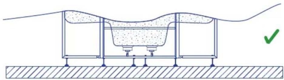
natural_image
Cross-sectional diagram of a mechanical or structural assembly with layered components and a green checkmark indicating a specific point (no text or symbols present)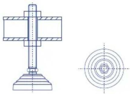
natural_image
Technical drawing of a mechanical assembly with cross-sectional and top views (no text or symbols)112
natural_image
Technical diagram of a structural support system with embedded concrete and foundation, showing no text or symbols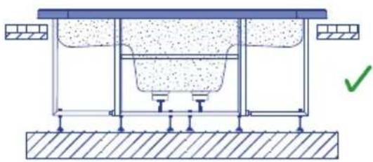
natural_image
Technical diagram of a structural support system with no visible text or symbols113
natural_image
Two mechanical diagrams showing a bent pipe or support structure with cross marks indicating failure or absence (no text or symbols present)116
| Elément | P total [W] | P phase [W] | I phase [A] | 20 > L [m] | 20 ≤ L 35 [m] | 35 ≤ L < 55 [m] |
| T | - | - | - | 4 | 6 | 10 |
| N | - | - | - | 4 | 6 | 10 |
| L1-L2-L3 | 14463 | 4821 | 25.4 | 4 | 6 | 10 |
KIT 16412CE
A
| Elément P | total[W] | P phase[W] | I phase[A] |
| R 6000 2000 9.0 | |||
| PF 820 820 3.8 | |||
| P1 1810 603 3.2 | |||
| P2 1810 603 3.2 | |||
| P3 0 0 0,0 | |||
| B 1300 433 3.8 | |||
| PTC --- | |||
| F --- | |||
| T --- |
B
Sc [mm²]
| Elément | P total [W] | P phase [W] | I phase [A] | 20 > L [m] | 20 ≤ L 35 [m] | 35 ≤ L < 55 [m] |
| T-- | -46 | 10 | ||||
| N- | --46 | 10 | ||||
| L1-L2-L3 | 14463 | 4821 25.4 46 | 10 |
KIT 04015CE
A
| Elément P | total[W] | P phase[W] | I phase[A] |
| R 6000 | 2000 9,0 | ||
| PF 600 | 600 2,7 | ||
| P1 1050 | 1050 4,9 | ||
| P2 0 0 0,0 | |||
| B | 1300 433 3,8 | ||
| PTC - | -- | ||
| F - | -- | ||
| T -- | - | ||
| T -- | - |
B
Sc [mm²]
| Elément P | total[W] | P phase[W] | I phase[A] | 20 > L[m] | 20 ≤ L 35[m] | 35 ≤ L < 55[m] |
| T --- 2.5 | 46 | |||||
| N --- | 2.5 | 46 | ||||
| L1-L2-L3 | 9012 | 3483 | 17.7 | 2.5 | 4 | 6 |
A
| Elément P | total[W] | P phase[W] | I phase[A] |
| R 6000 2000 9,0 | |||
| PF 820 820 3,8 | |||
| P1 1460 1460 6,8 | |||
| P2 0 0 0,0 | |||
| P3 0 0 0,0 | |||
| B 1300 433 3,8 | |||
| PTC --- | |||
| F | --- | ||
| T | --- |
B
Sc [mm²]
| Elément | P total [W] | P phase [W] | I phase [A] | 20 > L [m] | 20 ≤ L 35 [m] | 35 ≤ L < 55 [m] |
| T | - | - | - | 2.5 | 4 | 10 |
| N | - | - | - | 2.5 | 4 | 10 |
| L1-L2-L3 | 9642 3893 | 19,6 2,5 4 | 10 | |||
RACCORDEMENT DU CHAUFFE-EAU
text_image
Technical diagram of an electric motor assembly with labeled components and a close-up of its internal circuit board.PLAQUETTE DE CIRCUIT IMPRIMÉ
text_image
L3 CIRCULATION PUMP M6 12 VAC SPA LIGHT M5 MAX. 7W 12 VDC SOLENOID VALUE M9 LEVEL SENSORS 1- 2: Safety level 3: Min. level 4: Max. level 5: Common 6: 5V Power Supply F3 K1 M6 E5 SAT J4 V1 F6 2SAT C2 M5 V1 M4 C3 M9 L3 N3 K3 K2 J6 M7 J7 K10 F2 K4 J5 M8 F4 SAT V2 M3 Z K6 K7 IC2 J3 L7 L1 M9 LINE F1 N J2 V1 M1 M1 FLOW SENSOR 1: FLOW SWITCH 2: COMMON M8 CONTROL SPA BUTTONS 1: COMMON 2: JETS 1 3: JETS 2 4: INSERT COIN FUNC. Or LIGHT 5: JETS 3 6: BLOWER M2 Ph/ REDOX SYSTEM 230 M3 EXTERNAL HEAT EXCHANGER 24VAC119
RACCORDEMENTS DES BOUTONS TÉLÉCOMMANDÉS DU SPA
flowchart
graph TD
    subgraph Ventilateur
        A["Ventilateur"]
        B["Message massage 3"]
        C["Lumiere (facultatif)"]
        D["Pompe massage 2"]
        E["Pompe massage 1"]
    end
    subgraph Light pulse
        F["Ventilateur"]
        G["Lightre (facultatif)"]
        H["Message massage"]
    end
    A --> I["Line"]
    B --> I
    C --> I
    D --> I
    E --> I
    F --> J["Line"]
    G --> J
    H --> J
    I --> K["Line"]
    J --> L["Line"]
    style A fill:#f9f,stroke:#333
    style B fill:#f9f,stroke:#333
    style C fill:#f9f,stroke:#333
    style D fill:#f9f,stroke:#333
    style E fill:#f9f,stroke:#333
    style F fill:#f9f,stroke:#333
    style G fill:#f9f,stroke:#333
    style H fill:#f9f,stroke:#333
120
LUMIÈRE
text_image
150mm150mm125
4. MISE EN SERVICE
natural_image
Abstract graphic with a blue circular shape and a black upward arrow, no text or symbols present.126
natural_image
Simple diagram of circles inside a circle, no text or symbols presentnatural_image
Abstract circular logo with stylized wave-like symbols (no text or numbers)natural_image
Simple circular shape with a thin border, no text or symbols present.EN PRODUCTS: S PRODUKTER:
DE PRODUKTE: FI TOUTTEET:
FR PRODUITS: N PRODUKTER:
IT PRODOTTI: GR [PIONTA:
PT PRODUTOS:
NL PRODUKTEN:
RU продукт:
SPAS PÚBLICOS Y KITS
COMPACTOS
PUBLIC SPAS AND COMPACT
KITS
EN - EVIDENCE OF CONFORMITY
The products listed above are in compliance with :
2014/30/EU (Electromagnetic Compatibility), Directive 2014/35/EU (Low
Voltage) and with the European Standard EN 60335-2-41.
S - OVERENSSTEMMELESESERKL∅RING
OvenstΣende produkter oppfyller betingelsene elektromagnetiskdirektiv
2014/30/EU, lavpenningsdirektiv 2014/35/EU, og Europeisk Standard EN
60335-2-41.
FR - DECLARATION CONFORMITÉ
Signature/Qualification :
Underskrft/Stilling:
Signature/Qualification
Manager of Iberspa, S.L. by proxy
E-206-07/01/2020
! ACHTUNG
text_image
Technical diagram of a device's internal circuit with numbered components and directional flow arrowstext_image
Technical diagram of a mechanical or electrical device with numbered components and directional arrows indicating flow or movement.text_image
Technical schematic diagram of a mechanical or electrical system with numbered components and directional flow arrowstext_image
Technical schematic diagram of a mechanical or electrical device with numbered components and colored flow paths indicating connections.text_image
Technical diagram of a mechanical or electrical device with numbered components and directional arrows indicating flow or movement.natural_image
Technical line drawing of a mechanical pump or motor assembly (no text or symbols)106
natural_image
Technical line drawing of a mechanical assembly with cylindrical components and mounting flanges (no text or symbols)107
- FILTER
text_image
Technical diagram of a device's internal circuit with numbered components and directional flow arrowsnatural_image
Technical diagram of a structural support system with no visible text or symbols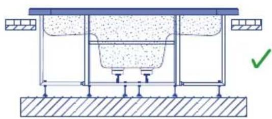
natural_image
Technical diagram of a structural support system with no visible text or symbols113
natural_image
Two identical diagrams showing a mechanical or electrical component with cross marks, no text or symbols present.116
| Bauteil | P Gesant [W] | P phase [W] | I phase [A] | 20 > L [m] | 20 ≤ L 35 [m] | 35 ≤ L < 55 [m] |
| T --- 2.5 | 46 | |||||
| N --- | 2.5 | 46 | ||||
| L1-L2-L3 | 9012 | 3483 | 17.7 | 2.5 | 4 | 6 |
A
| Bauteil P | Gesant [W] | P phase [W] | I phase [A] |
| R 6000 2000 9,0 | |||
| PF 820 820 3,8 | |||
| P1 1460 1460 6,8 | |||
| P2 0 0 0,0 | |||
| P3 0 0 0,0 | |||
| B 1300 433 3,8 | |||
| PTC --- | |||
| F | --- | ||
| T | --- |
B
Sc [mm²]
| Bauteil | P Gesant [W] | P phase [W] | I phase [A] | 20 > L [m] | 20 ≤ L 35 [m] | 35 ≤ L < 55 [m] |
| T | - | - | - | 2.5 | 4 | 10 |
| N | - | - | - | 2.5 | 4 | 10 |
| L1-L2-L3 | 9642 3893 | 19,6 2,5 4 | 10 | |||
CONECTION DES HEIZGERÄTES
text_image
Technical diagram of an electric motor assembly with labeled components and a close-up of its internal circuit board.natural_image
Pure electrical circuit lines without any symbols121
ANDERE ANSCHLÜSSE
text_image
150mm150mm4. INBETRIEBNAHME
natural_image
Abstract graphic with a blue circular shape and a black upward arrow, no text or symbols present.natural_image
Two symbols: a recycling symbol and a waste bin with an X-bracing (no text or labels)10. KONFORMITÄTSNACHWEIS

IBERSPA, S.L.
N-II km 516,8
Carrer Projecte II
25200 - Cervera (Lleida)
SPAIN
ES PRODUCTOS: DA PRODUKTER:
EN PRODUCTS: S PRODUKTER:
DE PRODUKTE: FI TOUTTEET:
FR PRODUITS: N PRODUKTER:
IT PRODOTTI: GR PIONTA:
PT PRODUTOS:
NL PRODUKTEN:
RU продукт:
SPAS PÚBLICOS Y KITS
COMPACTOS
PUBLIC SPAS AND COMPACT
KITS
EN - EVIDENCE OF CONFORMITY
The products listed above are in compliance with :
2014/30/EU (Electromagnetic Compatibility), Directive 2014/35/EU (Low
Voltage) and with the European Standard EN 60335-2-41.
S - OVERENSSTEMMELESESERKL∅RING
OvenstΣende produkter oppfyller betingelsene elektromagnetiskdirektiv
2014/30/EU, lavpenningsdirektiv 2014/35/EU, og Europeisk Standard EN
60335-2-41.
FR - DECLARATION CONFORMITÉ
Signature/Qualification: Underskrft/Stilling:
Manager of Iberspa, S.L. by proxy
E-206-07/01/2020
! ATTENZIONE
text_image
Technical diagram of a refrigeration or cooling system with numbered components and airflow pathstext_image
Technical diagram of a mechanical or electrical device with numbered components and directional arrows indicating flow or movement.text_image
Technical diagram of a mechanical or electrical device with numbered components and flow pathstext_image
Technical schematic diagram of a device with numbered components and colored flow paths indicating process flow.text_image
Technical diagram of a mechanical or electrical device with numbered components and directional arrows indicating flow or movement.natural_image
Technical line drawing of a mechanical pump or motor assembly (no text or symbols)106
• SCAMBIATORE ELETTRICO DI CALORE
natural_image
Technical line drawing of a mechanical assembly with cylindrical components and mounting brackets (no text or symbols)207
• FILTRO
text_image
Technical diagram of a device's internal circuit with numbered components and directional flow arrows• BLOWER AD USO CONTINUO
natural_image
Two identical diagrams showing a mechanical or electrical setup with no visible text, numbers, or symbols.116
text_image
LIGHT (12V) (to MG) SOLENOID VALVE (to MG) FLOW SENSOR (to M1) TEMP SENSOR (NTC) (to j1) PIEZO BUTTONS (to M1) 4/6.3A 4/6.3A 4/6.3A 4/6.3A 6000W 30mA 30mA A1 A2 MD L-1 MD L-3 MD L-5 MD L-7 4/6.3A 4/6.3A 4/6.3A 4/6.3A A2 MD L-2 MD L-4 MD L-6 MD L-8 LEVEL SENSOR (to Mg) PUMP 3 PUMP 2 PUMP 1 BLOWER HEATER 2700W 1810W 1810W 1300W 6000W PUMP 2 PUMP 1 BLOWER HEATER 2700W 1810W 1810W 1300W 6000W MOD. 43639 MOD. 43639 MOD. 43639 MOD. 43639 MOD. 43639 MOD. 43639 MOD. 43639 MOD. 43639 MOD. 43639 MOD. 43639 MOD. 43639 MOD. 43639 MOD. 43639 MOD. 43639 MOD. 43639 MOD. 43639 MOD. 43639 MOD. 43639 MOD. 43639 MOD. 43638 MOD. 43639 MOD. 43639 MOD. 43639 MOD. 43639 MOD. 43639 MOD. 43639 MOD. 43639 MOD. 43639 MOD. 43639 MOD. 43639 MOD. 43639 MOD. 4358 MOD. 43639 MOD. 43639 MOD. 43639 MOD. 43639 MOD. 43639 MOD. 43639 MOD. 43639 MOD. 43639 MOD. 43639 MOD. 43639 MOD. 43639 MOD. 4015 MOD. 4015 MOD. 4015 MOD. 4015 MOD. 4015 MOD. 4015 MOD. 4015 MOD. 4015 MOD. 4015 MOD. 4015 MOD. 4015 MOD. 4015 MOD. 4015 MOD. 456 OZONE (OPTIONAL) (M1 M4 M7 M10 PS2 J1 J2 J3 R S T N PS1 M1 M4 M7 M10 PS2 12 34 56 78 9 LEVEL SENSOR (to Mg) LEVEL SENSOR (to Mg) POWER SUPPLY N L-3 L-2 L-1 EARTH E E E E E E E E E E E E E E E E E E E E E E E E E E E E E E E E E E E E E E E E E E E E E E E E E E E E E E E E E E E E E E E E E E E E E E E E E E E E E E E E E E E E E E E E E E E E E E E E Automatic pH/ Redox Controller (OPTIONAL) (to M2)P max [W]
20 > L [m] 20 ≤ L 35 [m] 35 ≤ L < 55 [m]
| Sc [mm2] | 20 35 55 | |
| 0,5 882 504 321 | ||
| 1 1764 1008 641 | ||
| 1,5 2646 1512 962 | ||
| 2,5 4410 2520 1603 | ||
| 4 7055 4032 2566 | ||
| 6 10583 | 6047 3848 | |
| 10 17638 | 10079 | 6414 |
| 16 28221 | 16126 | 10262 |
KIT 43639
A
| Elemento | P Totale [W] | P fase [W] | I fase [A] |
| R | 6000 | 2000 | 9 |
| P.F | 820 | 273 | 1,6 |
| P.2 | 1810 | 603 | 3,2 |
| P.3 | 2700 | 900 | 3,2 |
| B | 1300 | 433 | 3,8 |
| PTC | - | - | - |
| F | - | - | - |
| T | - | - | - |
| T | - | - | - |
B
Sc [mm ^2 ]
| Elemento | P Totale [W] | P fase [W] | I fase [A] | 20 > L [m] | 20 ≤ L 35 [m] | 35 ≤ L < 55 [m] |
| T | - | - | - | 4 | 6 | 10 |
| N | - | - | - | 4 | 6 | 10 |
| L1-L2-L3 | 14463 | 4821 | 25,4 | 4 | 6 | 10 |
KIT 16412CE
A
| Elemento P Totale [W] | P fase [W] | I fase [A] | |
| R 6000 2000 9.0 | |||
| PF 820 820 3.8 | |||
| P1 1810 603 3.2 | |||
| P2 1810 603 3.2 | |||
| P3 0 0 0,0 | |||
| B 1300 433 3.8 | |||
| PTC - | - | - | |
| F | - | - | - |
| T | - | - | - |
B
Sc [mm²]
| Elemento | P Totale [W] | P fase [W] | I fase [A] | 20 > L [m] | 20 ≤ L 35 [m] | 35 ≤ L < 55 [m] |
| T | - | - | - | 4 | 6 | 10 |
| N | - | - | - | 4 | 6 | 10 |
| L1-L2-L3 | 14463 | 4821 | 25.4 | 4 | 6 | 10 |
KIT 04015CE
A
| Elemento P Totale [W] | P fase [W] | I fase [A] | |
| R 6000 | 2000 9,0 | ||
| PF 600 | 600 2,7 | ||
| P1 1050 | 1050 4,9 | ||
| P2 0 | 0 0,0 | ||
| B | 1300 433 3,8 | ||
| PTC - | - | - | |
| F | - | - | - |
| T | - | - | - |
| T | - | - | - |
B
Sc [mm²]
| Elemento | P Totale [W] | P fase [W] | I fase [A] | 20 > L [m] | 20 ≤ L 35 [m] | 35 ≤ L < 55 [m] |
| T - | - | -2.5 | 46 | |||
| N | - | - | - | 2.5 | 4 | 6 |
| L1-L2-L3 | 9012 | 3483 | 17.7 | 2.5 | 4 | 6 |
A
| Elemento P Totale [W] | P fase [W] I fase [A] | ||
| R 6000 2000 9,0 | |||
| PF 820 820 3,8 | |||
| P1 1460 1460 6,8 | |||
| P2 0 0 0,0 | |||
| P3 0 0 0,0 | |||
| B 1300 433 3,8 | |||
| PTC | - | - | - |
| F | - | - | - |
| T | - | - | - |
B
Sc [mm²]
| Elemento | P Totale [W] | P fase [W] | I fase [A] | 20 > L [m] | 20 ≤ L 35 [m] | 35 ≤ L < 55 [m] |
| T | - | - | - | 2.5 | 4 | 10 |
| N | - | - | - | 2.5 | 4 | 10 |
| L1-L2-L3 | 9642 3893 | 19,6 2,5 4 | 10 | |||
COLLEGAMENTI
text_image
Technical diagram of an electric motor assembly with labeled components and a close-up of its internal terminal block.CIRCUITO STAMPATO
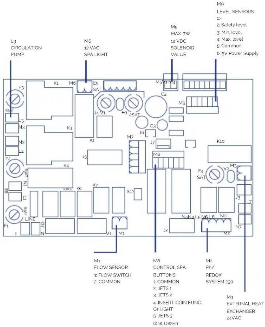
text_image
L3 CIRCULATION PUMP M6 12 VAC SPA LIGHT M5 MAX. 7W 12 VDC SOLENOID VALUE M9 LEVEL SENSORS 1:- 2: Safety level 3: Min. level 4: Max. level 5: Common 6: 5V Power Supply F3 K1 M6 E5 SAT J4 V1 F6 2SAT C2 M5V1 M4 M9 L3 N3 K3 K2 J6 C3 F2 K4 J5 M7 J7 K10 IN V89 K3K12 K6 K7 IC2 F1 LINE N J12 V1 M1 M1 FLOW SENSOR 1: FLOW SWITCH 2: COMMON M8 CONTROL SPA BUTTONS 1: COMMON 2: JETS 1 3: JETS 2 4: INSERT COIN FUNC. Or LIGHT 5: JETS 3 6: BLOWER M2 Ph/ REDOX SYSTEM 230 M3 EXTERNAL HEAT EXCHANGER 24VAC119
COLLEGAMENTO PULSANTI REMOTI SPA
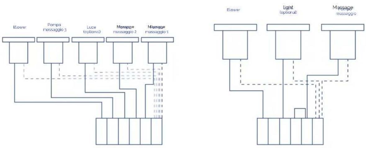
flowchart
graph TD
    A["Blower"] --> B["Pompa massaggio 3"]
    B --> C["Luce (optional)"]
    C --> D["Massage massaggio 2"]
    D --> E["Massage massaggio 1"]

    F["Blower"] --> G["Light optional"]
    G --> H["Massage massaggio"]

    style A fill:#f9f,stroke:#333
    style F fill:#f9f,stroke:#333

    subgraph "Light optional"
        I[" "] --> J[" "]
        K[" "] --> L[" "]
        M[" "] --> N[" "]
        O[" "] --> P[" "]
        Q[" "] --> R[" "]
        S[" "] --> T[" "]
        U[" "] --> V[" "]
        W[" "] --> X[" "]
        Y[" "] --> Z[" "]
        AA[" "] --> AB[" "]
        AC[" "] --> AD[" "]
        AE[" "] --> AF[" "]
        AG[" "] --> AH[" "]
        AI[" "] --> AJ[" "]
        AK[" "] --> AL[" "]
        AM[" "] --> AN[" "]
        AO[" "] --> AP[" "]
        AQ[" "] --> AR[" "]
        AS[" "] --> AT[" "]
        AU[" "] --> AV[" "]
        AW[" "] --> AX[" "]
        AY[" "] --> AZ[" "]
    end

    style A fill:#f9f,stroke:#333
    style F fill:#f9f,stroke:#333
    style G fill:#f9f,stroke:#333
    style H fill:#f9f,stroke:#333
    style I fill:#f9f,stroke:#333
    style J fill:#f9f,stroke:#333
    style K fill:#f9f,stroke:#333
    style L fill:#f9f,stroke:#333
    style M fill:#f9f,stroke:#333
    style N fill:#f9f,stroke:#333
    style O fill:#f9f,stroke:#333
    style P fill:#f9f,stroke:#333
    style Q fill:#f9f,stroke:#333
    style R fill:#f9f,stroke:#333
    style S fill:#f9f,stroke:#333
    style T fill:#f9f,stroke:#333
    style U fill:#f9f,stroke:#333
    style V fill:#f9f,stroke:#333
    style W fill:#f9f,stroke:#333
    style X fill:#f9f,stroke:#333
    style Y fill:#f9f,stroke:#333
    style Z fill:#f9f,stroke:#333
    style AA fill:#f9f,stroke:#333
    style AB fill:#f9f,stroke:#333
    style AC fill:#f9f,stroke:#333
    style AD fill:#f9f,stroke:#333
120
FARO
natural_image
Pure electrical circuit lines without any symbols121
ULTERIORI COLLEGAMENTI
text_image
150mm150mm4. AVVIAMENTO
natural_image
Abstract graphic with a blue circular shape and a black upward arrow, no text or symbols present.natural_image
Simple diagram of circles inside a circle, no text or symbols presentnatural_image
Abstract circular logo with stylized wave or flame-like design (no text or symbols)natural_image
Simple circular shape with no text, numbers, or symbolsLuce (opzionale)
127
6. MANUTENZIONE
natural_image
Two symbolic icons: a recycling symbol and a waste bin with a handle (no text or labels)EN PRODUCTS: S PRODUKTER:
DE PRODUKTE: FI TOUTTEET:
FR PRODUITS: N PRODUKTER:
IT PRODOTTI: GR [PIONTA:
PT PRODUTOS:
NL PRODUKTEN:
RU продукт:
SPAS PÚBLICOS Y KITS
COMPACTOS
PUBLIC SPAS AND COMPACT
KITS
EN - EVIDENCE OF CONFORMITY
The products listed above are in compliance with :
2014/30/EU (Electromagnetic Compatibility), Directive 2014/35/EU (Low
Voltage) and with the European Standard EN 60335-2-41.
S - OVERENSSTEMMELESESERKL∅RING
OvenstΣende produkter oppfyller betingelsene elektromagnetiskdirektiv
2014/30/EU, lavpenningsdirektiv 2014/35/EU, og Europeisk Standard EN
60335-2-41.
FR - DECLARATION CONFORMITÉ
Signature/Qualification :
Signature/Qualification
Firma/Qualifica :
Assinatura/Título
Manager of Iberspa, S.L. by proxy
E-206-07/01/2020
! ATENÇÃO
text_image
Technical diagram of a microwave oven system with numbered components and airflow pathstext_image
Technical diagram of a device with numbered components and airflow paths, likely for industrial or control system design.text_image
Technical schematic diagram of a mechanical or electrical device with numbered components and flow pathstext_image
Technical diagram of a mechanical or electrical device with numbered components and colored wiring pathstext_image
Technical diagram of a mechanical or electrical device with numbered components and directional arrows indicating flow or movement.104 por
1 Skimmer
2 Escoadouro
3 Desaguamento do spa
4 Bomba de filtragem
5 Válvula selectora
6 Filtro
7 Desaguamento do filtro
8 Aquecimento eléctrico
9 Sonda de temperatura
10 Detector de caudal
11 Ozonizador
12 Válvula de passagem
13 Válvula anti-retorno
14 Aberturas de retorno ao sp
105_por
natural_image
Technical line drawing of a mechanical pump or motor assembly (no text or symbols)106
natural_image
Technical line drawing of a mechanical assembly with cylindrical components and mounting flanges (no text or symbols)207
• FILTRO
natural_image
Technical diagram of a structural support system with no visible text or symbols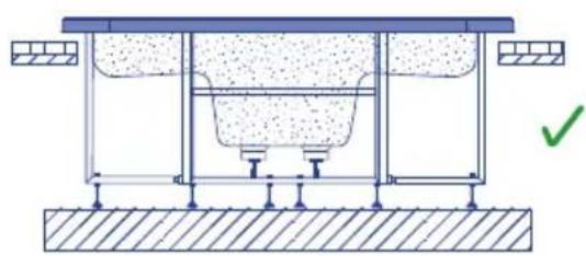
natural_image
Technical diagram of a structural support system with no visible text or symbols113
natural_image
Two identical diagrams showing a mechanical or electrical component with red X marks indicating failure or absence, no text or symbols present.116
text_image
Technical diagram of an electric motor assembly with labeled components and a close-up of its internal circuit board.PLACA DE CIRCUITO IMPRESSO
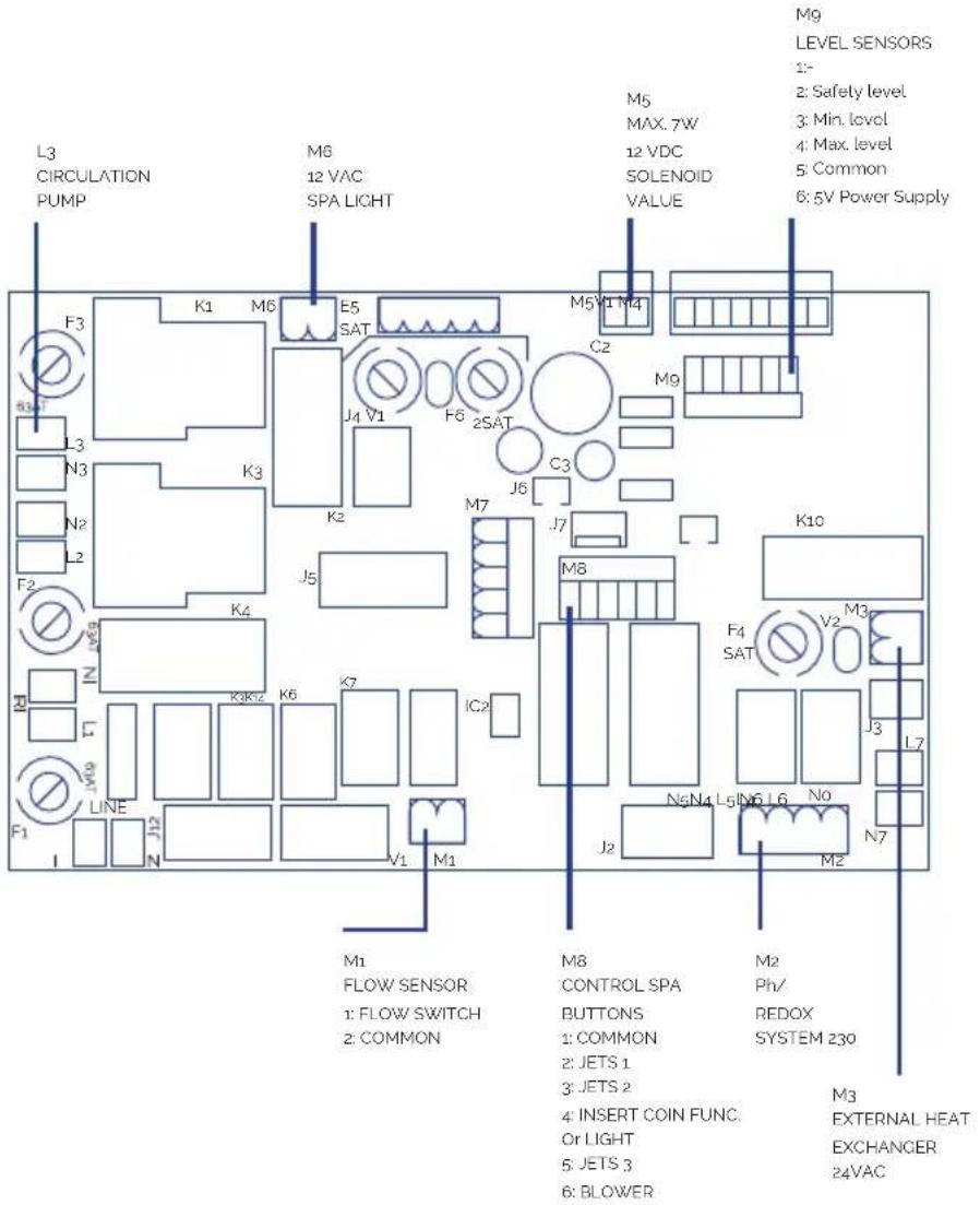
text_image
L3 CIRCULATION PUMP M6 12 VAC SPA LIGHT M5 MAX. 7W 12 VDC SOLENOID VALUE M9 LEVEL SENSORS 1- 2: Safety level 3: Min. level 4: Max. level 5: Common 6: 5V Power Supply F3 K1 M6 E5 SAT J4 V1 F6 2SAT C2 M5 V1 M4 C3 M9 L3 N3 K3 K2 J6 M7 J7 K10 F2 K4 J5 M8 F4 SAT V2 M3 Z K6 K7 IC2 J3 L7 L1 M9 LINE F1 N J2 V1 M1 M1 FLOW SENSOR 1: FLOW SWITCH 2: COMMON M8 CONTROL SPA BUTTONS 1: COMMON 2: JETS 1 3: JETS 2 4: INSERT COIN FUNC. Or LIGHT 5: JETS 3 6: BLOWER M2 Ph/ REDOX SYSTEM 230 M3 EXTERNAL HEAT EXCHANGER 24VAC119
natural_image
Pure electrical circuit lines without any symbols121
OUTRAS LIGAÇÕES
text_image
150mm150mmnatural_image
Abstract graphic with a blue circular shape and a black upward arrow, no text or symbols present.natural_image
Simple diagram of overlapping circles inside a circle (no text or symbols)natural_image
Abstract circular logo with stylized wave-like lines (no text or symbols)natural_image
Simple circular shape with no text, numbers, or symbolsLuz (opcional)
127
6. MANUTENÇÃO
natural_image
Two symbols: a recycling symbol and a waste bin with an X-bracing (no text or labels)EN PRODUCTS: S PRODUKTER:
DE PRODUKTE: FI TOUTTEET:
FR PRODUITS: N PRODUKTER:
IT PRODOTTI: GR PIONTA:
PT PRODUTOS:
NL PRODUKTEN:
RU продукт:
SPAS PÚBLICOS Y KITS
COMPACTOS
PUBLIC SPAS AND COMPACT
KITS
EN - EVIDENCE OF CONFORMITY
The products listed above are in compliance with :
2014/30/EU (Electromagnetic Compatibility), Directive 2014/35/EU (Low
Voltage) and with the European Standard EN 60335-2-41.
S - OVERENSSTEMMELESESERKL∅RING
OvenstΣende produkter oppfyller betingelsene elektromagnetiskdirektiv
2014/30/EU, lavpenningsdirektiv 2014/35/EU, og Europeisk Standard EN
60335-2-41.
FR - DECLARATION CONFORMITÉ
Signature/Qualification: Underskrft/Stilling:
Manager of Iberspa, S.L. by proxy
E-206-07/01/2020
! AANDACHT
text_image
Technical diagram of a refrigeration unit with numbered components and airflow paths1 Spa
2 Compensatiereservoir
3 Filtratiepomp
4 Filter
5 Elektrische verwarming
6 Ozonisator
7 Massagepompen
8 Ventilatiepomp
9 Elektrische bedieningskast
101_ned
• SPA MET SKIMMER
text_image
Technical diagram of a mechanical or electrical device with numbered components and directional arrows indicating flow or movement.1 Spa
2 Skimmer
3 Filtratiepomp
4 Filter
5 Elektrische verwarming
6 Ozonisator
7 Massagepompen
8 Ventilatiepomp
9 Elektrische bedieningskast
102DED
RECIRCULATIECIRCUIT
text_image
Technical schematic diagram of a mechanical or electrical device with numbered components and flow pathstext_image
Technical diagram of a device's internal components with numbered parts and colored wiring pathstext_image
Technical diagram of a mechanical or electrical device with numbered components and directional arrows indicating flow or movement.natural_image
Technical line drawing of a mechanical pump or motor assembly (no text or symbols)106
• ELEKTRISCHEWARMTEWISSELAAR
natural_image
Technical line drawing of a mechanical assembly with cylindrical components and mounting flanges (no text or symbols)107
- FILTER
text_image
Technical diagram of a device's internal circuit with numbered components and directional flow arrowsnatural_image
Technical diagram of a structural support system with embedded concrete layers and grounding, showing no text or symbols.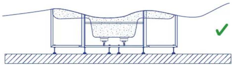
natural_image
Cross-sectional diagram of a mechanical or structural assembly with layered components and a green checkmark indicating a specific point (no text or symbols present)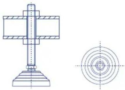
natural_image
Technical drawing of a mechanical assembly with cross-sectional and top views (no text or symbols)112
natural_image
Technical diagram of a structural support system with embedded concrete and foundation, showing no text or symbols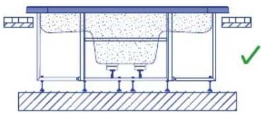
natural_image
Technical diagram of a structural support system with no visible text or symbols113
natural_image
Two mechanical diagrams showing a pipe connection with red X marks indicating failure or failure (no text or symbols present)116
| Element | P Total [W] | P Phase [W] | I Phase [A] | 20 > L [m] | 20 ≤ L 35 [m] | 35 ≤ L < 55 [m] |
| T | - | - | - | 4 | 6 | 10 |
| N | - | - | - | 4 | 6 | 10 |
| L1-L2-L3 | 14463 | 4821 | 25.4 | 4 | 6 | 10 |
KIT 16412CE
A
| Element P | Total[W] | P Phase[W] | I Phase[A] |
| R 6000 2000 9.0 | |||
| PF 820 820 3.8 | |||
| P1 1810 603 3.2 | |||
| P2 1810 603 3.2 | |||
| P3 0 0 0,0 | |||
| B 1300 433 3.8 | |||
| PTC --- | |||
| F | --- | ||
| T | --- |
B
Sc [mm²]
| Element | P Total [W] | P Phase [W] | I Phase [A] | 20 > L [m] | 20 ≤ L 35 [m] | 35 ≤ L < 55 [m] |
| T-- | -4 | 6 | 10 | |||
| N | - | - | - | 4 | 6 | 10 |
| L1-L2-L3 | 14463 | 4821 | 25.4 | 4 | 6 | 10 |
KIT 04015CE
A
| Element P | Total [W] | P Phase [W] | I Phase [A] |
| R 6000 | 2000 9,0 | ||
| PF 600 | 600 2,7 | ||
| P1 1050 | 1050 4,9 | ||
| P2 0 | 0 0,0 | ||
| B | 1300 433 3,8 | ||
| PTC - | -- | ||
| F | - | -- | |
| T | -- | - | |
| T | -- | - |
B
Sc [mm²]
| Element P | Total [W] | P Phase [W] | I Phase [A] | 20 > L [m] | 20 ≤ L 35 [m] | 35 ≤ L < 55 [m] |
| T -- | -2.5 | 46 | ||||
| N - | -- | 2.5 | 46 | |||
| L1-L2-L3 | 9012 | 3483 | 17.7 | 2.5 | 4 | 6 |
A
| Element P | Total [W] | P Phase [W] | I Phase [A] |
| R 6000 2000 9.0 | |||
| PF 820 820 3.8 | |||
| P1 1460 1460 6,8 | |||
| P2 0 0 0,0 | |||
| P3 0 0 0,0 | |||
| B 1300 433 3.8 | |||
| PTC - | - | - | |
| F | - | - | - |
| T | - | - | - |
B
Sc [mm²]
| Element | P Total [W] | P Phase [W] | I Phase [A] | 20 > L [m] | 20 ≤ L 35 [m] | 35 ≤ L < 55 [m] |
| T | - | - | - | 2.5 | 4 | 10 |
| N | - | - | - | 2.5 | 4 | 10 |
| L1-L2-L3 | 9642 3893 | 19,6 2,5 4 | 10 | |||
AANSLUITINGEN
text_image
Technical diagram of an electric motor assembly with labeled components and a close-up of its internal terminal block.PRINTPLAAT
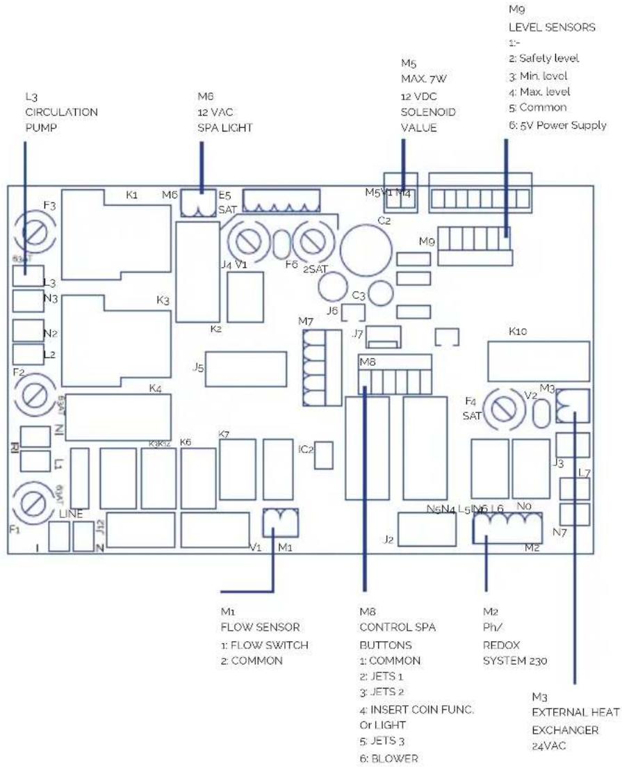
text_image
L3 CIRCULATION PUMP M6 12 VAC SPA LIGHT M5 MAX. 7W 12 VDC SOLENOID VALUE M9 LEVEL SENSORS 1: 2: Safety level 3: Min. level 4: Max. level 5: Common 6: 5V Power Supply F3 K1 M6 E5 SAT J4 V1 F6 2SAT C2 M5V1 M4 M9 L3 N3 K3 K2 J6 C3 F2 K4 J5 M7 J7 K10 IN V89 K3K12 K6 K7 IC2 F1 LINE N J12 V1 M1 M1 FLOW SENSOR 1: FLOW SWITCH 2: COMMON M8 CONTROL SPA BUTTONS 1: COMMON 2: JETS 1 3: JETS 2 4: INSERT COIN FUNC. Or LIGHT 5: JETS 3 6: BLOWER M2 Ph/ REDOX SYSTEM 230 M3 EXTERNAL HEAT EXCHANGER 24VAC119
AANSLUITING AFSTANDSBEDIENING BUBBELBAD
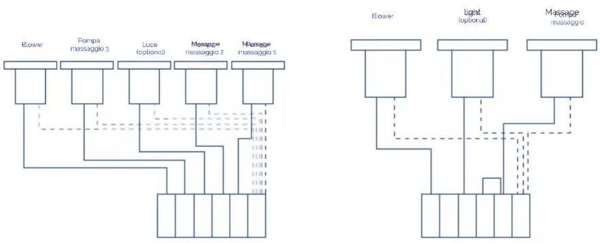
flowchart
graph TD
    A["Blower"] --> B["Pompa massaggio 3"]
    B --> C["Luce (optional)"]
    C --> D["Massage massaggio 2"]
    D --> E["Massage massaggio 1"]

    F["Blower"] --> G["Light optional"]
    G --> H["Massage massaggio"]

    style A fill:#f9f,stroke:#333
    style F fill:#f9f,stroke:#333

    subgraph "Light optional"
        I[" "] --> J[" "]
        K[" "] --> L[" "]
        M[" "] --> N[" "]
        O[" "] --> P[" "]
        Q[" "] --> R[" "]
        S[" "] --> T[" "]
        U[" "] --> V[" "]
        W[" "] --> X[" "]
        Y[" "] --> Z[" "]
        AA[" "] --> AB[" "]
        AC[" "] --> AD[" "]
        AE[" "] --> AF[" "]
        AG[" "] --> AH[" "]
        AI[" "] --> AJ[" "]
        AK[" "] --> AL[" "]
        AM[" "] --> AN[" "]
        AO[" "] --> AP[" "]
        AQ[" "] --> AR[" "]
        AS[" "] --> AT[" "]
        AU[" "] --> AV[" "]
        AW[" "] --> AX[" "]
        AY[" "] --> AZ[" "]
    end

    style A fill:#f9f,stroke:#333
    style F fill:#f9f,stroke:#333
    style G fill:#f9f,stroke:#333
    style H fill:#f9f,stroke:#333
    style I fill:#f9f,stroke:#333
    style J fill:#f9f,stroke:#333
    style K fill:#f9f,stroke:#333
    style L fill:#f9f,stroke:#333
    style M fill:#f9f,stroke:#333
    style N fill:#f9f,stroke:#333
    style O fill:#f9f,stroke:#333
    style P fill:#f9f,stroke:#333
    style Q fill:#f9f,stroke:#333
    style R fill:#f9f,stroke:#333
    style S fill:#f9f,stroke:#333
    style T fill:#f9f,stroke:#333
    style U fill:#f9f,stroke:#333
    style V fill:#f9f,stroke:#333
    style W fill:#f9f,stroke:#333
    style X fill:#f9f,stroke:#333
    style Y fill:#f9f,stroke:#333
    style Z fill:#f9f,stroke:#333
    style AA fill:#f9f,stroke:#333
    style AB fill:#f9f,stroke:#333
    style AC fill:#f9f,stroke:#333
    style AD fill:#f9f,stroke:#333
120
LAMP
natural_image
Pure electrical circuit lines without any symbols121
OVERIGE AANSLUITINGEN
text_image
150mm150mm125
4. INBEDRIJFSTELLING
natural_image
Abstract graphic with a blue circular shape and a black upward arrow, no text or symbols present.WAARSCHUWINGEN MET BETREKKING TOT DE VEILIGHEID
natural_image
Simple diagram of overlapping circles inside a circle (no text or symbols)natural_image
Abstract circular logo with stylized wave-like symbols (no text or numbers)Afstandsbediening watermassagepomp(en)

natural_image
Simple circular shape with no text, numbers, or symbolsLicht (optionele)
6. ONDERHOUD
natural_image
Two symbols: a recycling symbol and a waste bin with an X-bracing (no text or labels)10. CONFORMITEITSVERKLARING

IBERSPA, S.L.
N-II km 516,8
Carrer Projecte II
25200 - Cervera (Lleida)
SPAIN
ES PRODUCTOS: DA PRODUKTER:
EN PRODUCTS: S PRODUKTER:
DE PRODUKTE: A TOUTTEET:
FR PRODUITS: N PRODUKTER:
IT PRODOTTI: GR PIONTA:
PT PRODUTOS:
NL PRODUKTEN:
RU продукт:
SPAS PÚBLICOS Y KITS
COMPACTOS
PUBLIC SPAS AND COMPACT
KITS
EN - EVIDENCE OF CONFORMITY
The products listed above are in compliance with :
2014/30/EU (Electromagnetic Compatibility), Directive 2014/35/EU (Low
Voltage) and with the European Standard EN 60335-2-41.
S - OVERENSSTEMMELESESERKL∅RING
OvenstΣende produkter oppfyller betingelsene elektromagnetiskdirektiv
2014/30/EU, lavpenningsdirektiv 2014/35/EU, og Europeisk Standard EN
60335-2-41.
FR - DECLARATION CONFORMITÉ
Signature/Qualification :
Underskrft/Stilling:
Manager of Iberspa, S.L. by proxy
E-206-07/01/2020