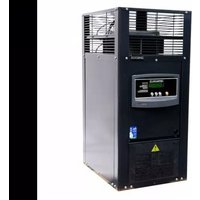
HX 70 - Heating ASTRALPOOL - Free user manual and instructions
Find the device manual for free HX 70 ASTRALPOOL in PDF.


| Product Type | Gas-fired pool and spa heater |
| Model | HX 70 |
| Dimensions (A x B x C x D) | 420 mm x 320 mm x 700 mm x 370 mm |
| Power Supply | 240 V AC, 10 A, 50/60 Hz |
| Gas Types | Natural Gas or Propane |
| Minimum Water Flow | 150 L/min |
| Maximum Water Flow | 450 L/min (external bypass required above) |
| Burner Pressure (Natural Gas) | 1.0 kPa |
| Burner Pressure (Propane) | 2.62 kPa |
| Water Connection Size | 40 mm PVC glue in |
| Gas Connection Size | 15 mm F.I. |
| Temperature Range | 10°C to 40°C (settable) |
| Safety Features | High limit thermostat (45°C), thermistor, pressure switch, electronic flame supervision, time delay |
| Fault Indication | Alpha-numeric codes on display (F1, F2, F3, Fo, L) |
| Outdoor Installation | Built-in balanced flue for outdoor use |
| Indoor Installation | Requires draught hood kit (Part No. 10133) and proper ventilation |
| Clearances (Outdoor, combustible) | Front: 500 mm; Sides: 300 mm; Rear: 300 mm; Above: 1500 mm |
| Recommended Water Chemistry | pH 7.2-7.6; Total Alkalinity 80-120 ppm; Calcium Hardness 150-250 ppm; Chlorine < 3 ppm; Bromine < 5 ppm; Salinity < 400 ppm |
| Maintenance Intervals | Monthly: run 15 min; Quarterly: check O-rings, surroundings; Annually: check gas pressures |
| Warranty | Cabinet/insulation: 5 years pro rata; Heat exchanger/burner: 2 years; Components: 12 months |
Frequently Asked Questions - HX 70 ASTRALPOOL
User questions about HX 70 ASTRALPOOL
0 question about this device. Answer the ones you know or ask your own.
Ask a new question about this device
Download the instructions for your Heating in PDF format for free! Find your manual HX 70 - ASTRALPOOL and take your electronic device back in hand. On this page are published all the documents necessary for the use of your device. HX 70 by ASTRALPOOL.
USER MANUAL HX 70 ASTRALPOOL
HX Series Pool & Spa Heater HX70 & HX120
INSTALLATION AND
OPERATING INSTRUCTIONS

natural_image
Exterior view of a black industrial air conditioning unit with control panel and warning label (no readable text or symbols)Index
Introduction
Introduction....3
Notice to Installers .... 3
Safety Rules....3
Operation
Lighting Instructions 4
Operating Instructions 4
Turning Gas Off 4
Chemical Balance 4
Corrosion Prevention in Heaters....5
Digital Thermostat Operation....6
Fault Indication....7
Maintenance
Maintenance Instructions....8
Energy saving Tips....8
Winter Operation 8
Installation
Installation Instructions....9
Flow Rates....9
Water Connections 9
Plumbing Diagram....9
Heater Dimensions....10
Indoor Installation 10
Ventilation....10
......11
Clearances 11
Electrical Connection 12
Gas Connection 12
Pressure Switch Adjustment....12
Starting the Heater 13
Testing Burner Pressure 13
Gas Conversion
Burner Conversion....14
Troubleshooting
Fault Finding and Remedies....15
Wiring diagram
HX Series Wiring Diagram....16
Maintenance
Maintenance of your Heater 17
Warranty
Terms and Conditions 18
Congratulations on your purchase of a AstralPool and Spa Heater. Proper installation and service of your new heating system and correct chemical maintenance of the water will ensure years of enjoyment. The HX Series Heater is a compact lightweight and efficient gas fired pool and spa heater. It is equipped with features that take advantage of new technology developed exclusively by AstralPool.
The AstralPool Heater can safely be connected to PVC pipe and has a built in balanced flue for outdoor installation. It accepts high flow rates which help the heater run cooler, giving greater performance and long life. In addition, the AstralPool Heater is equipped with electronic start up and an accurate electronic thermostat to ensure ease of use and accurate temperature control. The electronic display tells at a glance the operational status of the heater.
Note:
The appliance is not intended for use by young children or infirm person without supervision. Please ensure that young children are supervised to ensure that they do not play with the appliance.
NOTICE TO INSTALLERS
This appliance must be installed by an authorized person.
This appliance must be installed in accordance with the installation instructions, local gas fitting regulations, the Standards Australia Installation Code AS5601 and any other relevant statutory authorities.
Refer to data plate for details of gas type, gas consumption and burner pressure.
SAFETY RULES
- Spa or hot tub water temperature should never exceed 40^ C.
- Drinking of alcoholic beverages before or during spa or hot tub use can cause drowsiness which could lead to unconsciousness and subsequently result in drowning.
- Pregnant women beware! Soaking in water above 38^ C can cause foetal damage during the first three months of pregnancy.
- Before entering the spa or hot tub, the user should check the water temperature with an accurate thermometer, spa or hot tub thermostats may err in regulating water temperatures by as much as 2^ C.
- Persons with a medical history of heart disease, circulatory problems, diabetes or blood pressure problems should obtain their physician's advice before using spas or hot tubs.
- Persons taking medications which induce drowsiness, such as tranquillisers, antihistamines or anticoagulants, should not use spas or hot tubs.
WARNING: Should overheating occur or the gas supply fail to shut off, turn off the manual gas control valve to the appliance. Do not use this heater if any part has been under water.
For your safety – read before lighting
This appliance is equipped with an ignition device which automatically lights the burner. Do not try to light the burner by hand.
BEFORE OPERATING smell all around the appliance area for gas. Be sure to smell next to the floor because some gas is heavier than air and will settle on the floor.
WHAT TO DO IF YOU SMELL GAS. Do not try to light any appliance. Do not touch any electrical switch. Do not use any telephone in your building. Immediately call your gas supplier from a neighbour's house.
DO NOT PLACE ARTICLES ON OR AGAINST THIS APPLIANCE.
DO NOT USE OR STORE FLAMMABLE MATERIALS NEAR THIS APPLIANCE.
DO NO SPRAY AEROSOLS IN THE VICINITY OF THIS APPLIANCE WHILE IT IS IN OPERATION.
OPERATING INSTRUCTIONS
- STOP! Read the safety information above.
- Turn off electric power to appliance.
- This appliance is equipped with an ignition device which automatically lights the burner. Do not try to light the burner by hand.
- Wait five minutes to clear out any gas. If you then smell gas, STOP! Refer to instructions above.
- Turn filtration pump on.
- Turn on power to the heater and press the pool/spa button to select pool or spa mode.
- Set thermostat to desired setting and the ON/OFF switch to turn the heater ON.
- The heater will ignite in around 10 seconds.
- If the appliance will not operate, follow instructions 5 to 7 above. If the appliance still does not ignite, call your service technician.
TO TURN GAS OFF TO APPLIANCE
- Turn off all electrical power to the appliance.
- Turn off gas tap in gas line prior to heater.
CHEMICAL BALANCE
It is imperative that correct chemical balance be maintained in your pool and spa water, otherwise corrosion of your heater may occur. Corrosion of the heat exchanger voids warranty. Your local pool shop specialist or spa retailer can advise correct chemical balance. Your water should be checked and maintained regularly by a pool water professional. As a guide the following parameters may be used.
pH 7.2 to 7.6
Total Alkalinity 80 to 120 ppm
Calcium Hardness 150 to 250 ppm
Salinity 400ppm max. Excessive salt can damage your heater.
You should test your water chemical balance at least on a weekly basis.
Excessive sanitiser can damage your heater. Chlorine should not exceed 3 ppm and bromine should not exceed 5 ppm. Salt chlorinators, especially when used on spa pools or indoor or covered pools, can easily produce excessive chlorine levels which will damage the heater internals.
All pool and spa heaters use copper or copper nickel to make their heat exchangers as it is the most efficient material in transferring heat from the combustion chamber into the water. The typical life expectancy of a well maintained pool/spa heater is between 8 and 15 years.
Often the same heat exchanger used in residential and commercial boilers and hot water systems will have a life expectancy of 20 years.
The addition of sanitisers (Chlorine, Bromine etc.) and other water balancing and conditioning chemicals can increase the rate of wear and tear on the heat exchanger and associated parts in your heater.
There are three most common reasons for heat exchanger corrosion which can be avoided with a little care and attention.
-
Excessive Sanitiser. This means too much Chlorine or Bromine in the water. Be careful, if the level of Chlorine or Bromine is excessively high your test kit (and the pool shops) may not read accurately or indeed may show a nil reading. Any time a salt chlorinator is operating for extended periods, (when heating the swimming pool from cold), particularly if the weather is overcast or the pool enclosed or covered, the Chlorine level may exceed normal levels. When heating a Spa Pool, turn the chlorinator down or off for the duration of the heating period.
-
Out of balance water. The water balance is a combination of pH, total alkalinity, Calcium hardness and temperature. These measurements must be at the correct levels to maintain balanced water and effective sanitation of your pool. Balanced water will help prevent corrosion of your heater. Balanced water should be between 7.2 - 7.6 pH.
-
The addition of acid to lower pH. Acid must always be added in small quantities and spread over the pool surface evenly, not added in to the skimmer. Do not add a litre at a time, add a cupful each day to lower your pH.
-
Never add chemicals to skimmer - dilute and circulate as far away as possible from skimmer.
If you have a salt chlorinated INDOOR pool or COVERED pool be very careful of the level of Chlorine being produced. If you use a salt chlorinated spa be very careful of the level of Chlorine as the Chlorinator is usually sized for the pool and therefore should be switched off when heating the spa. Leaving the chlorinator on can raise the chlorine level very rapidly in a small volume of water.
These comments are intended as a guide only and are not definitive answers or recommendations on pool water chemistry. AstralPool's intention is to provide a little understanding of the potential problems of water chemistry and the dangers of corrosion to heaters (and other pool equipment and fittings).
You should always seek the advice of your local pool shop professional and provide him with as much information and feedback as possible when analysing your pool and spa water and obviously be sure to tell him you have a heater connected to the system even though it may not be in constant use.
YOUR WATER SHOULD BE ADJUSTED & BALANCED PRIOR TO ANY CORRODED PARTS BEING REPLACED.
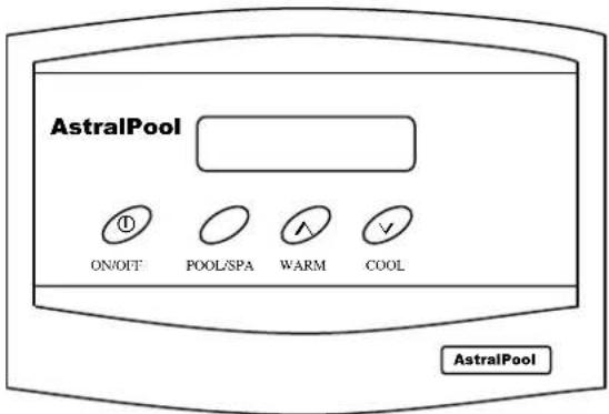
DESCRIPTION
The sophisticated digital thermostat provides temperature read out, set point temperature and operating status of the heater. The electronic display indicates the operational status of the heater and any fault conditions.
TEMPERATURE DISPLAY
The temperature display indicates water temperature in the inlet of the heater. Therefore the pump must be operating for an accurate pool or spa water temperature to be displayed.
Comfortable pool temperature is between 26^ and 30^ . Normal spa temperature is between 36^ and 38^ . To select your desired temperature press the up or down button repeatedly until the desired temperature is reached.
To prevent rapid cycling of the heater, the thermostat has an inbuilt time delay which prevents the heater from turning on for two minutes after the set point has been reached. If the time delay is activated, the symbol "L" will be displayed. This is part of normal operation.
The thermostat can be set to temperatures between 10^ C and 40^ C. It also incorporates several safety features including a 45^ C high limit function to prevent overheating of the pool or spa. On simultaneous shut down of the circulating pump and heater, the water within the heater may exceed 45^ C for a short period. If the pump and heater are restarted during this period, the thermostat will go into a standby mode and prevent the heater from relighting until the temperature within the heater has dropped below the set temperature.
Should the thermostat fail to stop the heater at the set point or at 40^ C, there are three temperature limiting safety devices designed to lock the heater out and prevent further heating. A lock out condition is indicated by the symbols F1 or F2. To reset a lock out condition, turn the power off for five seconds.
Under fault conditions the thermostat will display a set of alpha numeric symbols to indicate the status of the heater. The meaning of each symbol and action to be taken are listed as follows:
SYMBOL MEANING ACTION
Temp Display Unit has power. No action.
| Fo | Heater locked off, thermistor | If water temperature reads greater than o^ , phone for |
| Wire disconnected or water | ||
| At o^ (freeze conditions). Service. | ||
| F1 | Thermostat reads greater than 45°C. | Allow water to cool, turn heater off then on again. |
| F2 | Mechanical Hi Limit greater Than 45°C. | Allow water to cool, turn heater off then on again. |
| F3 | Thermistor fault | Phone for Service |
| L | Heater locked out on time | No action. Heater will |
| Delay for 2 minutes. | Automatically reset after | |
| Time delay. | ||
| Or switch off then on again | ||
| For immediate ignition. | ||

Pump operating & sufficient No action. Water pressure to operate heater
Thermostat calling for heat. No action. Electronic Flame Supervision Operating.
It is recommended that you check the following at least every six months and at the beginning of every swimming season.
- Examine the balanced flue or indoor draught diverter. Make sure there are no obstructions to the flow of air to, or flue products from, the appliance.
- Visually check the burner flames. If the flame appears yellow, the burner should be cleaned by a qualified service technician.
- Keep the heater area clear and free of combustibles and flammable liquids. Chlorine should not be stored in the vicinity of the heater. Chlorine vapours, when drawn through a heater, can rapidly cause corrosion of the heat exchanger.
- Keep the heater area free from garden refuse and debris. This will help prevent insects nesting in the unit and ensure extended life and reliability of your heater.
ENERGY SAVING TIPS
- If possible, keep pool or spa covered when not in use. This will not only cut heating costs, but will also keep dirt and debris from settling in the pool and conserve chemicals.
- Reduce pool thermostat setting to 28^ C or lower. This is accepted as a comfortable and healthy swimming temperature.
- Use an accurate thermometer.
- Set timeclock to start filtration and circulation system no earlier than daybreak. The pool loses less heat at this time.
- For pools that are only used on weekends, it is not necessary to leave the thermostat set at 28^ C. During the week, lower it by an amount that can easily be achieved in one day (generally 5^ C to 8^ C).
- During the winter or while on vacation, turn the heater off.
- Set up a regular program of preventative maintenance for the heater each new swimming season. Check heat exchanger, controls, burner operation etc.
WINTER OPERATION
If the pool won't be used for a month or more, turn the heater off at the main gas valve. For areas where there is no danger of freezing, water should circulate through your heater all year long even though you are not heating your pool.
Where freezing is possible, it is necessary to drain the water from the heater. This may be done by loosening the inlet or outlet barrel union. If the heater is below water level, isolate it from the pool first by closing shut off valves before and after the heater.
CAUTION: If the heater has been drained for freezing conditions, do not turn on until the system is circulating water.
THIS APPLIANCE MUST BE INSTALLED BY AN AUTHORISED PERSON. Refer to heater data plate for specifications of gas type, gas consumption, burner pressure and water pressure.
This appliance must be installed in accordance with local regulations and Standards Australia Installation Code AS5601.
FLOW RATES
The AstralPool Heater requires a minimum of 150 litres per minute flow and the maximum permissible flow rate is 450 litres per minute. For flow rates in excess of 450 litres per minute, an external by-pass valve must be fitted.
WATER CONNECTIONS
The heater should always be installed after the pump and filter. The water connections are located on the right hand side of the heater. Left hand connection models are available by special order. The inlet and outlet are clearly marked. Water connections require 40 mm PVC glue in plumbing.
All automatic sanitising devices must be installed after the heater and in such a way that the sanitiser cannot enter the heater without first mixing with the water in the pool or spa. Sanitisers that are connected prior to the heater will void heater warranty.
The AstralPool Heater incorporates a balanced flue terminal and is suitable for outdoor installation.
PLUMBING DIAGRAM

flowchart
graph LR
    A["From Pool"] --> B["Pump"]
    B --> C["Filter"]
    C --> D["Heater"]
    D --> E["Chlorinator"]
    E --> F["Return to Pool"]
    G["PVC Piping"] --> H["To Solar"]
    I["From Solar"] --> J["To Solar"]
    K["Heater Diagram"] --> L["Plumbing in high pressure 40mm or 50mm PVC pipe"]
    K --> M["Connection to heater in Class 12 or higher"]
    K --> N["All automatic Chlorinators or Sanitisers Must be installed after heater"]
HEATER DIMENSIONS
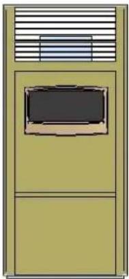
natural_image
Illustration of a vintage-style cabinet or storage unit with a central monitor and ventilation grille (no text or symbols)Model
HX 70
HX 120

Dimension A
420mm
515mm
Dimension B
320mm
390mm

Dimension C
700mm
800mm
Dimension D
370mm
400mm
INDOOR INSTALLATION
If the HX Heater is to be installed indoors, an indoor draught hood kit must be purchased from AstralPool and installed on the HX Heater to convert it to an indoor model.
Product code numbers for draught hood kits are:
| Heater model | Indoor top model | Flue size | Part number |
| HX 70 | DH 07 | 125 mm | 10133 |
| HX 120 | DH 12 | 125 mm | 10134 |
A flue no smaller than the draught diverter diameter must be installed and terminated with an approved gas flue cowl (not a Chinaman's hat) 600mm above any roofline that is within 1.5 metres horizontally from the flue.
VENTILATION
When installing the heater indoors, it is imperative that an adequate supply of fresh air is provided for combustion. Failure to provide adequate ventilation voids all warranties and may be a danger to persons or property.
Two permanent openings shall be provided directly to outside. The openings shall be located to ensure the distance between the top of the upper opening and the ceiling of the room or enclosure, and the distance between the bottom of the lower opening and the floor of the room or enclosure does not exceed 5% of the height of the room or enclosure.
The minimum vertical dimension of any free ventilation opening shall be 6 mm. The minimum free ventilation area provided by each opening shall be:
MODEL
HX 70
HX 120
AREA
23,000 mm ^4
39,000 mm ^2
The following diagram is provided as a guide only. All flueing and installation work must be carried out by an authorized person. Flueing must conform to local regulations and to A.G.A. installation code AS5601. Care must be taken to provide the correct ventilation and correct flueing materials in close proximity to combustible surfaces.

flowchart
graph TD
    A["Approved gas termination cowl"] --> B["Bolted sleeve to connect flue"]
    B --> C["Draft diverter purchased from AstralPool"]
    C --> D["Upper grille for fresh air ventilation"]
    C --> E["Lower grille for fresh air ventilation"]
An indoor draught diverter must be purchased from AstralPool and fitted to unit in accordance with AstralPool's Instructions and Installation Codes before the heater can be enclosed.
Do not install spa blowers in the same room as a gas heater. This is potentially dangerous to spa users.
Do not store chemicals or fuel in the same room as the gas heater. This may cause fire or explosion. When installing in a garage the HX Heater must be installed 450mm above floor level.
CLEARANCES
The heater must be installed at least 500 mm from any combustible surface. Clearances must comply with AS5601.
Outdoor Clearances from non combustible surfaces are:
| Front | 500mm |
| Both sides | 300mm |
| Rear | 300mm |
| Above | 1500mm |
| Combustible Surfaces | 500mm Minimum |
Indoor Clearances from non-combustible surfaces are:
| Front | 500mm |
| Both sides | 150mm |
| Rear | 150mm |
| Above | 1500mm |
| Combustible Surfaces | 500mm Minimum |
Heater must be installed on a fireproof base.
ELECTRICAL CONNECTION
The heater is supplied with a standard 10 amp 3 pin plug for connection to a 240V 10 amp GPO. The heater incorporates a 240/24 VAC transformer which supplies power to the control circuit. All pool or spa equipment connected to mains power should be protected by an RCD circuit breaker. It is recommended, where possible that the heater is connected to the same time clock or power supply as the circulating pump.
GAS CONNECTION
The gas connection is on the rear of the heater. A 15 mm F.I. connection is provided for gas line connection. An approved manual shut off valve must be installed in the gas fitting line before the heater and should be sized the same as the gas fitting line to prevent excessive pressure drop in the gas pipe.
The gas fitting line should be installed by an authorised person and comply with local regulations and Standards Australia code AS5601. The gas line from the meter will usually be of a larger size than the gas inlet connection. Therefore a reduction to the heater connection fitting will be necessary. The reduction should be as close to the heater as possible.
Before using the heater, test all connections for leaks using soapy water.
The heater gas valve has a built in pressure regulator and 18 pressure test point. On starting the heater, a manometer must be used and burner pressure checked against the heater data plate. The gas valve regulator may need to be adjusted to correct manifold pressure. Incorrect burner pressure may void warranty.
PRESSURE SWITCH ADJUSTMENT
The AstralPool Heater incorporates a water pressure switch which allows the burner to operate only when the circulating pump is operating.
It is imperative that the following be undertaken by the person who is commissioning (first starting) your pool or spa heater. On initial start up of the heater it may be necessary to adjust the water pressure activation switch.
This switch is located behind the top rear panel and is screwed into the water manifold. The pressure switch is designed to allow operation of the heater only when the circulating pump is turned on and there is sufficient water flow through the heater. It must shut the heater down immediately the pump is switched off.
To check the operation of the switch:
- Connect the heater to mains power supply. The thermostat should not yet display "θ".
- Turn on pump. The thermostat should now display "θ".
- Turn pump off. The thermostat should no longer display "θ".
- If display does not respond in this way, adjust the pressure switch as detailed below. If display responds correctly, perform a final check with the heater operating.- See the section below titled "Starting the heater"
To adjust pressure switch:
- Connect the heater to mains power supply
- Turn pump off
- Slide toggle on side of pressure switch up to allow knurled wheel to be turned
- Turn knurled wheel anti-clockwise (as viewed from above) until " " is displayed
- Turn knurled wheel clockwise until "θ" disappears
- Continue to wind clockwise for a further half turn (180 degrees)
- When the switch is correctly set, slide the toggle down to lock the knurled wheel in position.
WARNING: If the pressure switch cannot be adjusted correctly, DO NOT OPERATE THE HEATER, contact AstralPool or an Authorised Service Agent for advice.
Inst174 HX Series Pool & Spa Heater V10.16
- Perform a final check with the heater operating.- See the section below titled "Starting the heater".
Pressure Switch Adjustment

STARTING THE HEATER
- Purge gas line of any air and wait five minutes for gas to clear.
- Turn power to unit on. Thermostat should now operate and indicate water temperature.
- Turn circulating pump on Thermostat should display "θ" to indicate water flow.
- Set thermostat to "ON" and press the "^" button water temperature. Thermostat should now display: ^* repeatedly until set temperature is greater than
- After a few seconds, the burner should ignite.
- While leaving the heater on, turn the pump off and on at 15 second intervals, six times. Make sure the heater turns off and on each time. If it does not, adjust the pressure switch as detailed above.
It is imperative that the heater is installed so that it does not operate when the circulating pump stops. Recommended methods to achieve this are:
a) Correct adjustment of internal pressure switch. Ensure heater does not turn on two or three minutes after circulating pump is turned off.
b) Interlock power supply of circulating pump and heater so that if timer or power turns circulating pump off, heater is also turned off.
c) Installation of an external flow switch may be preferred under certain installations where internal pressure switch does not turn heater off when circulator stops.
TESTING BURNER PRESSURE
- Set thermostat to "OFF"
- Set up manometer
- Remove screw from 1/8 brass test point located on outlet side of gas valve
- Connect manometer tube to test point
- Set thermostat to "ON" and wait for burner to ignite
- Once burner has ignited, the manometer must indicate the nominal burner pressure listed below
- To adjust gas valve regulator, remove regulator adjustment cap and, using a screwdriver, turn plastic bush clockwise to increase, anti-clockwise to decrease burner pressure
- When burner pressure is correctly set, set thermostat to "OFF"
- Refit test point screw and fibre washer
- Refit regulator adjustment cap.
Maximum inlet gas pressure is:
Natural Gas 3.5 kPa
Propane Gas 3.5 kPa
Nominal burner pressure is:
| HX 70 | HX 120 | |
| Natural Gas | 1.0 kPa | 0.92 kPa |
| Propane Gas | 2.62 kPa | 2.62 kPa |
BURNER CONVERSION HX 70
- Turn off gas supply to unit.
- Turn off power supply to pump and heater.
- Remove front access door.
- Disconnect gas supply tube from burner manifold.
- Remove burner support bracket at the front left of the heater.
- Remove the two Phillips head screws securing the angle brackets at the end of the manifold tube to combustion chamber support angles.
- Disengage the angle bracket at the front of the manifold from the slot in the combustion chamber support angle, lower the front of the burner assembly and withdraw.
- Remove the four Phillips head screws securing the injector manifold to the burner tray.
- Remove burner injectors and replace with desired gas type injectors.
- Remove regulator screw cap from top of gas valve.
- Turn plastic plug anti-clockwise until fully removed and withdraw spring.
- Insert spring for desired gas type and re-install plastic plug.
- Re-install burner assembly and reconnect gas supply.
- Check gas system for leaks.
- Commence lighting procedure as described above.
- Adjust burner pressure as described above.
| HX 70 | ||
| GAS TYPE | INJECTOR SIZE | BURNER PRESSURE |
| NATURAL | 1.25 mm | 0.92 kPa |
| PROPANE | 0.79 mm | 2.62 kPa |
BURNER CONVERSION HX 120
- Turn off gas supply to unit.
- Turn off power supply to pump and heater.
- Remove front access door.
- Disconnect gas supply tube from burner manifold.
- Remove burner support bracket at the front left of the heater.
- Remove the two Phillips head screws securing the angle brackets at the end of the manifold tube to combustion chamber support angles.
- Disengage the angle bracket at the front of the manifold from the slot in the combustion chamber support angle, lower the front of the burner assembly and withdraw.
- Remove the four Phillips head screws securing the injector manifold to the burner tray.
- Remove burner injectors and replace with desired gas type injectors.
- Remove gas valve and replace.
- For Natural gas models use White Rogers valve model 36G22 type 210 and for Propane use model 36G24 type 205
- Re-install burner assembly and reconnect gas supply.
- Check gas system for leaks.
- Commence lighting procedure as described above.
- Adjust burner pressure as described above.
| HX 120 | ||
| GAS TYPE | INJECTOR SIZE | BURNER PRESSURE |
| NATURAL | 1.25 mm | 0.92 kPa |
| PROPANE | 0.79 mm | 2.62 kPa |
TROUBLESHOOTING
| HEATER WILL NOT LIGHT | |
| Possible cause | Remedy |
| Automatic ignition system fails | Check if power to heater is turned on and pump is in operation |
| Pump not running | Start pump |
| Pump airlocked | Check for leaks |
| Filter dirty | Clean filter |
| Pump strainer basket clogged | Clean strainer |
| Defective gas control | Shut off gas supply and call for service |
| Thermostat turned off | Turn on |
| Set temperature lower than water temperature | Increase set temperature |
| Water too hot - fault condition displayed | Refer to fault indication table |
| HEATER SHORT CYCLING (RAPID ON AND OFF OPERATION) | |
| Possible cause | Remedy |
| Insufficient water flow | Clean filter and pump strainer |
| Defective wiring | Repair or replace wiring |
| Defective high limit or thermostat | Repair or replace |
| HEATER MAKING KNOCKING NOISES | |
| Possible cause | Remedy |
| Heater operating after pump has shut off | Shut off gas supply and call for service |
| Heat exchanger scaled | Shut off gas supply and call for service |
If the heater cannot be made to perform correctly, please contact the AstralPool office closest to you.

flowchart
graph TD
    A["HX SERIES IV THERMOSTAT"] --> B["GENUS IV THERMOSTAT"]
    B --> C["6 PIN PLUG"]
    C --> D["4 PIN PLUG"]
    D --> E["BRIDGING JACK"]
    C --> F["VIOLET"]
    F --> G["SENSOR"]
    G --> H["HI LIMIT N/C 55°"]
    H --> I["HI LIMIT N/C 45°"]
    I --> J["BROWN"]
    J --> K["GREEN/YELLOW"]
    K --> L["GAS VALVE"]
    M["IGNITION MODULE"] --> N["TH"]
    M --> O["V1"]
    M --> P["Y2"]
    Q["IGNITOR/FLAME SENSOR"] --> R["IGNITOR"]
    R --> S["GND"]
    S --> T["S1"]
    U["TRANSFORMER"] --> V["A"]
    U --> W["N"]
    U --> X["E"]
    Y["EARTH POST"] --> Z["Ground"]
Maintenance of your heater
Maintenance Schedule: Your new product incorporates moving parts and withstands high velocity water with chemicals in it. Some of these parts will wear in the normal course of use and require regular checks and maintenance. Performing these checks and maintenance will identify parts that have worn and require repair/replacement before further serious damage is sustained. A small amount of regular care and attention to your pool equipment will help ensure long life and trouble free performance.
To protect against extremes of temperature, your unit is vented to allow expensive electronics to cool. Ants and some insects are often attracted to the warmer, dry environment inside the enclosure. We recommend that, with power turned off, you spray a surface insecticide on the surfaces surrounding the control to prevent ant and insect ingress. Repeat every three months or as necessary.
| Timing | Maintenance Check | Service action (if required) |
| Monthly | Operate heater for 15 min to clear residues and ensure correct operation | Start circulation pump and turn heater on, leaving to run for a few minutes. This will clear flue passages and keep components working properly |
| Three Monthly | Check inlet/outlet o’rings for leaks | Isolate Pump, turn power off, clean and grease O rings or replace if necessary |
| Three Monthly | Check surroundings for leaves, debris and flooding | Remove debris from around the base of the hearer and rectify if any flooding. Clear vegetation from around the flue |
| Check for insects/ants | Spray a surface insecticide on the surfaces around the unit to prevent ant and insect ingress | |
| Annually | Check gas pressures | Call Service technician to perform annual gas checks and routine maintenance |
Important note: Regular maintenance is important to ensure long life and trouble free performance of your pool equipment. If unable to perform the maintenance yourself, contact your local AstralPool office who will arrange a trained service technician to perform the maintenance for you.
Record your Equipment details here for quick reference:
Model No.: ____
Serial No.: ____
AstralPool Australia Pty Ltd (ABN 97 007 284 504) ("AstralPool") provides the following warranty in relation to its HX Series of Pool & Spa Heater – HX70 & HX120 ("Product").
Our goods come with guarantees that cannot be excluded under the Australian Consumer Law. You are entitled to a replacement or refund for a major failure and for compensation for any other reasonably foreseeable loss or damage. You are also entitled to have the goods repaired or replaced if the goods fail to be of acceptable quality and the failure does not amount to a major failure.
The benefits of this warranty are in addition to any rights and remedies imposed by Australian State and Federal legislation that cannot be excluded. Nothing in this warranty is to be interpreted as excluding, restricting or modifying any State or Federal legislation applicable to the supply of goods and services which cannot be excluded, restricted or modified.
WARRANTY
AstralPool warrants that, subject to the exclusions and limitations below, the Product will be free from defects in materials and workmanship during the warranty period. The warranty periods are set out below and commence 30 days after the date of purchase (to allow for installation). The warranty period may vary for different parts of the Product.
| Parts | Warranty Period |
| Cabinet, refractory insulation & combustion chamber | 5 years pro rata |
| Heat exchanger, burner, inlet&outlet water headers | 2 years |
| Components | 12 months |
If a defect appears in the Product before the end of the warranty period and AstralPool finds the Product to be defective in materials or workmanship, AstralPool will, in its sole discretion, either:
(a) replace or repair the Product or the defective part of the Product free of charge; or
(b) Cause the Product or the defective part of the Product to be replaced or repaired by an Authorised AstralPool Service Agent free of charge.
AstralPool reserves the right to replace defective parts of the Product with parts and components of similar quality, grade and composition where an identical part or component is not available.
Goods presented for repair may be replaced by refurbished goods of the same type rather than being repaired. Refurbished parts may be used to repair the goods.
WARRANTY CLAIMS
- If a fault covered by warranty occurs, the customer must first contact AstralPool at the contact address listed below, or an Authorised AstralPool Service Agent.
- Any warranty claim must be accompanied by:
(a) proof of purchase;
(b) full details of the alleged defect; and
(c) appropriate documentation (such as historical and maintenance records).
- The customer must make the Product available to AstralPool or its Authorised AstralPool Service Agent for inspection and testing. AstralPool or its Authorised AstralPool Service Agent will attend the premises where the Product is installed for inspection and testing. If the Product is installed:
(a) outside a capital city metropolitan area; and
(b) is not within a 20 km radius of an Authorised AstralPool Service Agent; then the customer may have to pay a travel fee.
- If such inspection and testing finds no defect in the Product, the customer must pay AstralPool's usual costs of service work and testing. If such inspection and testing finds a defect that is not covered by this warranty, the customer must pay AstralPool's usual costs of service work plus any parts and labour required to repair the Product, unless recoverable from AstralPool on the failure of any statutory guarantee under the ACL.
Exclusions
The warranty will not apply where:
(a) the customer is in breach of the Terms and Conditions of Sale;
(b) the Product was used for a purpose other than one it was intended for;
(c) the Product was repaired, modified or altered by any person other than AstralPool;
(d) the Product has not been installed, maintained and/or operated in complete compliance with the installation and operating instructions and any instructions by AstralPool;
(e) the Product has been subject to accident, negligence, alteration, abuse or misuse.
The warranty does not extend to:
a) normal wear and tear;
b) weather and other environmental conditions including but not limited to storm, flood, and/or heat wave damage; or
c) service and maintenance items.
a) normal wear and tear; b) weather and other environmental conditions including but not limited to storm, flood, and/or heat wave damage; or c) service and maintenance items.
Examples of exclusions include but are not limited to:
- accident, neglect, alteration, abuse or misuse.
• Corrosion of the heat exchanger caused by improper water chemical balance.
Commercial Installations
On commercial installations, such as health clubs, motels/hotels and hydrotherapy facilities, the warranty is limited to parts and in field labour (within capital city metropolitan areas or 20 km radius of Authorised AstralPool Service Agents) for a period of 12 months from the date of purchase plus 30 days to allow for installation.
LIMITATIONS
AstralPool makes no express warranties or representations other than set out in this warranty.
The repair or replacement of the Product or part of the Product is the absolute limit of AstralPool's liability under this express warranty.

INST174

sales@astralpool.com.au
www.astralpool.com.au



- HX Series Pool & Spa Heater HX70 & HX120
- INSTALLATION AND
- OPERATING INSTRUCTIONS
- Index
- Introduction
- Operation
- Maintenance
- Installation
- Gas Conversion
- Troubleshooting
- Wiring diagram
- Warranty
- Note:
- NOTICE TO INSTALLERS
- SAFETY RULES
- For your safety – read before lighting
- TO TURN GAS OFF TO APPLIANCE
- CHEMICAL BALANCE
- DESCRIPTION
- TEMPERATURE DISPLAY
- SYMBOL MEANING ACTION
- ENERGY SAVING TIPS
- WINTER OPERATION
- FLOW RATES
- WATER CONNECTIONS
- PLUMBING DIAGRAM
- HEATER DIMENSIONS
- INDOOR INSTALLATION
- VENTILATION
- CLEARANCES
- ELECTRICAL CONNECTION
- GAS CONNECTION
- PRESSURE SWITCH ADJUSTMENT
- To check the operation of the switch:
- To adjust pressure switch:
- STARTING THE HEATER
- TESTING BURNER PRESSURE
- BURNER CONVERSION HX 70
- BURNER CONVERSION HX 120
- Maintenance of your heater
- WARRANTY CLAIMS
- Exclusions
- Commercial Installations
- LIMITATIONS
Brand : ASTRALPOOL
Model : HX 70
Category : Heating