
CR1300 - Industrial control IFM - Free user manual and instructions
Find the device manual for free CR1300 IFM in PDF.


User questions about CR1300 IFM
0 question about this device. Answer the ones you know or ask your own.
Ask a new question about this device
Download the instructions for your Industrial control in PDF format for free! Find your manual CR1300 - IFM and take your electronic device back in hand. On this page are published all the documents necessary for the use of your device. CR1300 by IFM.
USER MANUAL CR1300 IFM
Operating instructions
ecomat
Panel
CR1300
Contents
1 Preliminary note 3
1.1 Symbols used 3
1.2 Warnings.... 3
2 Safety instructions.... 4
3 Intended use.... 5
4 Function 6
5 Installation.... 7
5.1 Mounting accessories 7
5.2 General installation instructions 7
5.2.1 Location for mounting accessories 7
6 Electrical connection.... 8
6.1 Connection accessories 8
6.2 General wiring information 8
6.3 Fuses 8
6.4 Operating voltage and CAN interface 9
7 Operating and display elements 10
8 Operation 11
8.1 CAN messages for the keys 11
8.2 CAN messages for the rotary button 11
8.3 CAN messages for the illumination 12
8.4 Combination with an ecomat
Display 4.3" 12
9 Maintenance, repair and disposal 13
1 Preliminary note
You will find instructions, technical data, approvals and further information using the QR code on the unit / packaging or at documentation.ifm.com.
1.1 Symbols used
√ Requirement
Instructions
Reaction, result
[...] Designation of keys, buttons or indications
→ Cross-reference

Important note
Non-compliance may result in malfunction or interference.

Information
Supplementary note
1.2 Warnings
Warnings indicate the possibility of personal injury and damage to property. This enables safe product handling. Warnings are graded as follows:

WARNING
Warning of serious personal injury
▷ If the warning is not observed, fatal and serious injuries are possible.

CAUTION
Warning of minor to moderate personal injury
▷ If the warning is not observed, minor to moderate injuries are possible.
ATTENTION
Warning of damage to property
▷ If the warning is not observed, damage to property is possible.
2 Safety instructions
- The unit described is a subcomponent for integration into a system.
- The system architect is responsible for the safety of the system.
-
The system architect undertakes to perform a risk assessment and to create documentation in accordance with legal and normative requirements to be provided to the operator and user of the system. This documentation must contain all necessary information and safety instructions for the operator, the user and, if applicable, for any service personnel authorised by the architect of the system.
-
Read this document before setting up the product and keep it during the entire service life.
- The product must be suitable for the corresponding applications and environmental conditions without any restrictions.
- Only use the product for its intended purpose (→ Intended use).
- If the operating instructions or the technical data are not adhered to, personal injury and/or damage to property may occur.
- The manufacturer assumes no liability or warranty for any consequences caused by tampering with the product or incorrect use by the operator.
• Installation, electrical connection, set-up, programming, configuration, operation and maintenance of the product must be carried out by personnel qualified and authorised for the respective activity. - Protect units and cables against damage.
- Replace damaged units, otherwise the technical data and safety will be impaired.
- Observe applicable documents.
3 Intended use
The ecomat
Panel is only intended and set up for connection to ecomat
Displays.
Communication takes place via the special ifm interface or via a free CAN interface. Integration into a system is carried out via J1939.

The unit is not approved for safety-related tasks in the field of operator protection.
▶ Use the device only within the limits of the technical data ( → Technical data).
4 Function
• Rotary button with turn, tilt and push function
- 6 programmable function keys with RGB background illumination for night design
- Plastic housing for panel mounting and surface mounting in the cabin
• CAN interface with SAE J 1939 protocol
5 Installation
5.1 Mounting accessories
The unit is supplied without mounting accessories.
More information about available accessories at www.ifm.com
5.2 General installation instructions
5.2.1 Location for mounting accessories
The back of the device has been prepared for fixing the mounting accessories.

Fig. 1: Locator for mounting accessories (back of the unit)
Usable M6 thread depth: ≤ 18 mm
6 Electrical connection
6.1 Connection accessories
More information about available accessories at www.ifm.com
6.2 General wiring information

Fig. 2: 4-pin Tyco MQS connector (back of the unit)
1: Supply, CAN
ATTENTION
Wrong connection may cause damage to the device.
▶ Observe the safety instructions.
The short-circuit / reverse polarity protection of the device applies to the operating voltage connections.
▶ Basically lay all supply and signal cables separately.
▶ Lay supply and signal cables away from the device using the shortest possible route.
▶ Provide all outgoing cables with a strain relief 200 mm behind the cable entry.
6.3 Fuses
▶ To protect the unit use fuses for the operating voltages.
| Designation | Potential | Connector 1 | Fuse |
| Operating voltage | 9...32 V DC | Pin 4 | max. 2 A |
Terminal designation to DIN 72552
6.4 Operating voltage and CAN interface
| Tyco MQS connector (4-pole) | Pin | Potential | |
 | CAN-Interface | 1 | CAN_L |
| 2 | CAN_H | ||
| Operating voltage | 3 | GND | |
| 4 | 9...32 V DC | ||

CAN Interface: 2.0 A/B, ISO 11898; Default 250 kbit/s
CAN protocol: SAE J1939
7 Operating and display elements
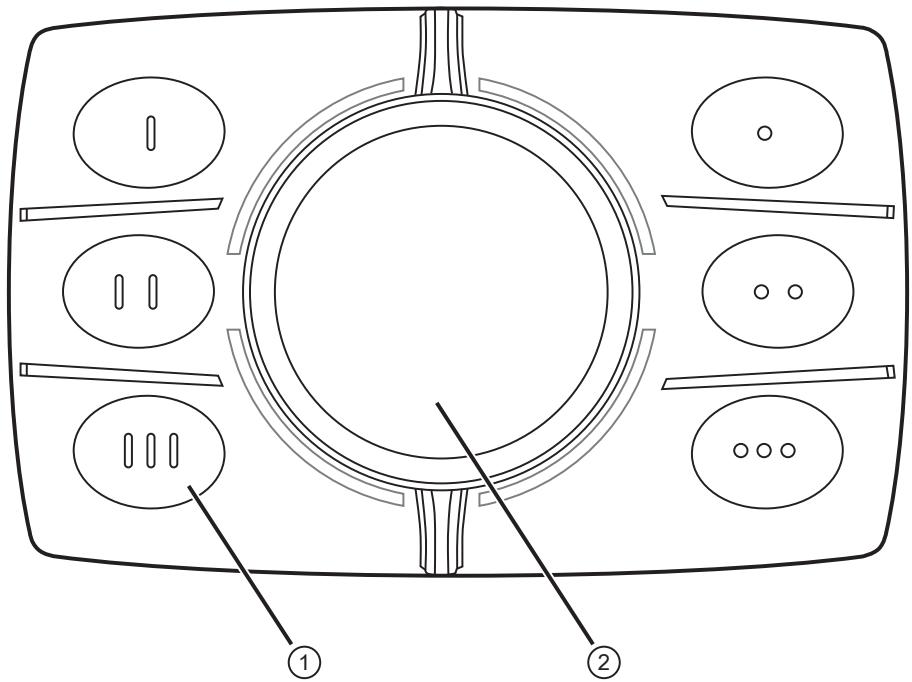
1: 6 freely programmable function keys with RGB background illumination
2: Rotary button with turn, tilt and push function
8 Operation
Communication is compatible with the CAN SAE J1939 standard.
• 250 kBaud CAN baud rate
• Transmission speed of the keys cyclically every 30 ms
• Dynamic addressing via J1939 possible
- The display elements keep the status of the last message.
8.1 CAN messages for the keys
CAN identifier: 0x10FF6487(default)
J1939 PGN: 0xFF64
J1939 priority: 0x4
| CAN message (J1939) | Description | Value |
| KeyPad_J1939_I Drive_1 Byte address: Byte 1, bit 0 | Status key 1 | 0 = key not pressed1 = key pressed |
| KeyPad_J1939_I Drive_2 Byte address: Byte 1, bit 2 | Status key 2 | 0 = key not pressed1 = key pressed |
| KeyPad_J1939_I Drive_3 Byte address: Byte 1, bit 4 | Status key 3 | 0 = key not pressed1 = key pressed |
| KeyPad_J1939_I Drive_4 Byte address: Byte 1, bit 6 | Status key 4 | 0 = key not pressed1 = key pressed |
| KeyPad_J1939_I Drive_5 Byte address: Byte 2, bit 0 | Status key 5 | 0 = key not pressed1 = key pressed |
| KeyPad_J1939_I Drive_6 Byte address: Byte 2, bit 2 | Status key 6 | 0 = key not pressed1 = key pressed |
8.2 CAN messages for the rotary button
CAN identifier: 0x10FF6487(default)
J1939 PGN: 0xFF64
J1939 priority: 0x4
| CAN message (J1939) | Description | Value |
| KeyPad_J1939_I Drive_EncValByte address: Byte 3 | Number of stops that the rotary button has been turned since the last query | 0...2424 = one full turn |
| KeyPad_J1939_I Drive_EncDirByte address: Byte 3, bit 5 | Rotational direction | 0 = clockwise1 = anti-clockwise |
| KeyPad_J1939_I Drive_Enter Byte address: Byte 3, bit 6 | Rotary knob pressed | 0 = rotary knob not pressed1 = rotary knob pressed |
| KeyPad_J1939_I Drive_LeftByte address: Byte 4, bit 0 | Rotary k nob tilted to the left | 0 = rotary knob not tilted1 = rotary knob tilted |
| KeyPad_J1939_I Drive_Right Byte address: Byte 4, bit 2 | Rotary button tilted to the right | 0 = rotary knob not tilted1 = rotary knob tilted |
| KeyPad_J1939_I Drive_UpByte address: Byte 4, bit 4 | Rotary button tilted upwards | 0 = rotary knob not tilted1 = rotary knob tilted |
| KeyPad_J1939_I Drive_DownByte address: Byte 4, bit 6 | Rotary button tilted downwards | 0 = rotary knob not tilted1 = rotary knob tilted |
8.3 CAN messages for the illumination
All CAN messages for the illumination have a data length of 8 bytes and a value range of 0...255.
| CAN message (J1939) | Byte 1 | Byte 2 | Byte 3 | Byte 4 | Byte 5 | Byte 6 | Byte 7 | Byte 8 |
| LIGHT_J1939_BUTTON1_2_INTENSITY CAN ID: 0x18FF7587 (default) J1939 PGN: 0xFF75 J1939 priority: 0x06 | key 1 | key 2 | ||||||
| R | G | B | R | G | B | FF | FF | |
| LIGHT_J1939_BUTTON3_4_INTENSITY CAN ID: 0x18FF7687 (default) J1939 PGN: 0xFF76 J1939 priority: 0x06 | key 3 | key 4 | ||||||
| R | G | B | R | R | G | B | R | |
| LIGHT_J1939_BUTTON5_6_INTENSITY CAN ID: 0x18FF7787 (default) J1939 PGN: 0xFF77 J1939 priority: 0x06 | key 5 | key 6 | ||||||
| R | G | B | R | R | G | B | R | |
Example: Trigger key 1 and key 2 to light orange
| CAN message (J1939) | Byte 1 | Byte 2 | Byte 3 | Byte 4 | Byte 5 | Byte 6 | Byte 7 | Byte 8 |
| Example CAN message ID:16x18FF7587 | key 1 | key 2 | ||||||
| R | G | B | R | G | B | FF | FF | |
| ifm orange (255 R, 110 G, 0 B) | 255 | 110 | 0 | 255 | 110 | 0 | 255 | 255 |
8.4 Combination with an ecomat
Display 4.3"
Setting up the ecomat
Panel in conjunction with an ecomat
Display 4.3":
▶ Connect the CAN bus of the ecomat
Panel to the CAN bus connection of the ecomat
Display 4.3". (→ Operating instructions of the ecomat
Display 4.3)
▶ In the [Services] menu, enable the ecomat
Panel in the setup mode of the "ecomat
Display4.3".
9 Maintenance, repair and disposal
The unit is maintenance-free.
▶ Contact ifm in case of malfunction.
▶ The device must only be repaired by the manufacturer. Observe the safety instructions ( → 2 Safety instructions).
Cleaning the device:
▶ Disconnect the device from the voltage supply.
▶ Clean the device from dirt using a soft, chemically untreated and dry micro-fibre cloth.
Disposal:
▶ After use, dispose of the unit in an environmentally friendly way in accordance with the applicable national regulations.
- 1 PRELIMINARY NOTE
- 1.1 SYMBOLS USED
- 1.2 WARNINGS
- 2 SAFETY INSTRUCTIONS
- 3 INTENDED USE
- 4 FUNCTION
- 5 INSTALLATION
- 5.1 MOUNTING ACCESSORIES
- 5.2 GENERAL INSTALLATION INSTRUCTIONS
- 5.2.1 LOCATION FOR MOUNTING ACCESSORIES
- 6 ELECTRICAL CONNECTION
- 6.1 CONNECTION ACCESSORIES
- 6.2 GENERAL WIRING INFORMATION
- 6.3 FUSES
- 6.4 OPERATING VOLTAGE AND CAN INTERFACE
- 7 OPERATING AND DISPLAY ELEMENTS
- 8 OPERATION
- 8.1 CAN MESSAGES FOR THE KEYS
- 8.2 CAN MESSAGES FOR THE ROTARY BUTTON
- 8.3 CAN MESSAGES FOR THE ILLUMINATION
- 8.4 COMBINATION WITH AN ECOMATDISPLAY 4.3
- 9 MAINTENANCE, REPAIR AND DISPOSAL
Brand : IFM
Model : CR1300
Category : Industrial control