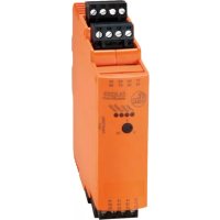
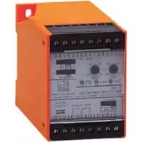
DL0203 - Electrical relay IFM - Free user manual and instructions
Find the device manual for free DL0203 IFM in PDF.


User questions about DL0203 IFM
0 question about this device. Answer the ones you know or ask your own.
Ask a new question about this device
Download the instructions for your Electrical relay in PDF format for free! Find your manual DL0203 - IFM and take your electronic device back in hand. On this page are published all the documents necessary for the use of your device. DL0203 by IFM.
USER MANUAL DL0203 IFM
Operating instructions
Level control relay
DL0203
Contents
1 Preliminary note.... 3
1.1 Symbols used.... 3
1.2 Warnings.... 3
1.3 Safety symbol on the device 3
2 Safety instructions 4
2.1 Cybersecurity 4
3 Transport, handling and storage 5
4 Intended use 6
5 Function 7
5.1 Switching diagram.... 8
6 Installation.... 9
6.1 Removing the unit 10
6.2 Installation of the sensors 10
7 Electrical connection 11
7.1 Overview.... 11
7.2 General wiring information.... 11
7.3 Notes on wiring 12
7.4 Pluggable cage clamps 12
7.5 Voltage supply (power) 12
7.5.1 AC voltage supply 13
7.5.2 DC voltage supply 13
7.5.3 External DC power supply for inputs and transistor output.... 13
7.6 Inputs.... 13
7.6.1 Connection of sensor 1 (upper level).... 14
7.6.2 Connection of sensor 2 (lower level).... 14
7.7 Outputs.... 14
7.7.1 Relay output.... 14
7.7.2 Transistor output 15
7.7.3 Connection of the valve or pump 15
8 Operating and display elements.... 16
8.1 Potentiometer.... 16
8.2 LEDs 16
9 Settings.... 17
9.1 Input delay 17
10 Troubleshooting.... 18
11 Maintenance, repair and disposal 19
11.1 Maintenance 19
11.2 Cleaning the housing surface 19
11.3 Repair 19
11.4 Disposal 19
1 Preliminary note
You will find instructions, technical data, approvals and further information using the QR code on the unit / packaging or at documentation.ifm.com.
1.1 Symbols used
√ Requirement
Instruction
Reaction, result
bold Designation of keys, buttons or indications
→ Cross-reference without link
→ Cross-reference with link

Important note
Non-compliance may result in malfunction or interference

Information
Supplementary note
1.2 Warnings
Warnings indicate the possibility of personal injury and damage to property. This enables safe product handling. Warnings are graded as follows:

WARNING
Warning of serious personal injury
▷ If the warning is not observed, fatal and serious injuries are possible.

CAUTION
Warning of minor to moderate personal injury
▷ If the warning is not observed, minor to moderate injuries are possible.

ATTENTION
Warning of damage to property
▷ If the warning is not observed, damage to property is possible.
1.3 Safety symbol on the device

Safety symbol on the device:
▶ Adhere to the operating instructions for the safe operation of the unit.
2 Safety instructions
- The unit described is a subcomponent for integration into a system.
- The system architect is responsible for the safety of the system.
-
The system architect undertakes to perform a risk assessment and to create documentation in accordance with legal and normative requirements to be provided to the operator and user of the system. This documentation must contain all necessary information and safety instructions for the operator, the user and, if applicable, for any service personnel authorised by the architect of the system.
-
Read this document before setting up the product and keep it during the entire service life.
- The product must be suitable for the corresponding applications and environmental conditions without any restrictions.
- Only use the product for its intended purpose (→ Intended use).
- If the operating instructions or the technical data are not adhered to, personal injury and/or damage to property may occur.
- The manufacturer assumes no liability or warranty for any consequences caused by tampering with the product or incorrect use by the operator.
- Installation, electrical connection, set-up, programming, configuration, operation and maintenance of the product must be carried out by personnel qualified and authorised for the respective activity.
- Protect units and cables against damage.
- Replace damaged units, otherwise the technical data and safety will be impaired.
- Observe applicable documents.
2.1 Cybersecurity
Installation
The device is suitable for operation in a secure environment according to IEC 62443-1-1.
▶ Carry out a risk assessment of the system according to IEC 62443-1-1.
▶ Take measures to ensure physical security. The device has no built-in protection against unauthorised access.
3 Transport, handling and storage
▶ Store the device in its original packaging.
▶ When the device is to be stored again, use the original packaging or pack the device in suitable packaging.
▶ Observe the permissible ambient conditions for the device during storage (→ Technical data).

WARNING
Storage without sufficient protection for pollution degree 2
▷ Risk of electric shock when connecting the device
▶ Store the device in its original packaging.
▶ Otherwise, ensure pollution degree 2 for the device during storage.
4 Intended use
The device is used to keep a medium level between 2 sensors. To do so it controls the inlet of a tank (e.g. valve or pump).
The device receives signals from 2 external sensors and switches its outputs according to the adjustable input delay. The input delay protects against unintended switching caused by waves on a medium surface.
Sensor supply and transistor output are equipped with an independent overload/short circuit protection.

The device is not suited for environments with particular requirements on mechanical stability (e.g. shock/vibration).
▶ Observe the operating conditions (→ Technical data at www.ifm.com).
5 Function

Fig. 1: Level control
1: Sensor 1 with normally closed output for input 1 (upper level)
2: Sensor 2 with normally open output for input 2 (lower level)
3: Tank with liquid or dry bulk material
4: Valve or pump (inlet)
5: Relay output
6: Transistor output
7: PLC or signalling device
| Process | relay |
| After switching on the device | de-energised |
| Level is below both sensors | energised |
| Level is above both sensors | de-energised |
| Level is between the sensors | depending on the previous state |
Relay energised = switched (transistor output conductive)
5.1 Switching diagram

1: Level of the medium
2: Sensor 1 with normally closed output for input 1 (upper level)
3: Sensor 2 with normally open output for input 2 (lower level)
4: Power supply
5: Output
SP1: Sensor 1 switch point (upper level)
SP2: Sensor 2 switch point (lower level)
X: Input delay (Input delay 17)
Relay energised, i.e. switched (transistor output switched)
6 Installation
▶ Disconnect power.
To ensure correct operation, install the device in a housing that can only be opened using a tool or in a locked control cabinet (both protection rating IP 54 or higher) as an enclosure in accordance with EN61010-1.

Always comply with pollution degree 2 for the device.
▶ Install the device vertically on a 35 mm DIN rail.


Leave enough space ( ≥ 50 mm) between the device and the top and bottom of the control cabinet to enable air circulation and to avoid excessive heating.

ATTENTION
If units are mounted side by side, inadmissible heating may occur between the units.
▷ Malfunction / damage is possible.
▶ Take into account the internal heating of all devices when mounting different devices side by side and observe the environmental conditions for each device.
6.1 Removing the unit

6.2 Installation of the sensors
▶ Follow the manufacturer's installation instructions.
7 Electrical connection
7.1 Overview

Fig. 2: Wiring

Fig. 3: Terminal overview

All GND connections are internally connected with each other.

The terminals 1 and 2 are internally interconnected. The terminals 3 and 4 are internally interconnected. The terminals 21 and 22 are internally interconnected. The terminals 23 and 24 are internally interconnected.
7.2 General wiring information

The unit must be connected by a qualified electrician.
▶ Observe the national and international regulations for the installation of electrical equipment.

WARNING
Use of unconnected terminals
▷ Electric shock possible.
▶ Do not use unconnected terminals (n.c.) which are not shown in the drawing as support point terminals.
▷ Protection guaranteed.
Accessible surfaces of the device are insulated from the circuits with basic insulation according to IEC 61010-1 (mains circuit of overvoltage category II up to 300 V nominal mains voltage).
This does not apply to connection areas and cooling openings (IP20).
The AC voltage supply and relay circuit are insulated from the DC voltage supply and from each other with reinforced insulation according to IEC 61010-1 (mains circuit of overvoltage category II up to 300 V nominal mains voltage).
The external wiring has to be carried out in a way that ensures the required separation from other circuits.
7.3 Notes on wiring
Maximum length of the connection cables:
• 30 m at each terminal

It is recommended to lay all cables in the control cabinet in cable ducts.
Alternatively:
Provide all outgoing cables with suitable strain relief after a maximum of 400 mm. Observe the minimum bending radius of the cables (information from the cable manufacturer).
7.4 Pluggable cage clamps

ATTENTION
No IP 20 protection without connector.
▶ Cover unused connectors with terminals.
▷ Observe IP 20.

Stripping length for the supplied cage clamps: 9...10 mm
Connections that may carry mains voltage are colour-coded red on the pluggable cage clamps. This prevents them from being accidentally plugged on the SELV terminals.
Network terminals:
- AC supply (21...24)
- Out relay (17...20)
SELV terminals:
- DC supply (1...4)
- Input1 / Input2 (5...8)
• Out transistor (13...16)

WARNING
Use of non-coded cage clamps for AC supply (21...24) and out relay (17...20)
▷ Cage clamps carrying mains voltage may be accidentally plugged onto SELV-terminals of the device.
▷ Electric shock possible.
▶ Only use the supplied coded cage clamps for network terminals.
▷ Protection guaranteed.
7.5 Voltage supply (power)
▶ Voltage supply see type label.
▶ Connect the device only to one of the possible voltage connections, either to terminals 21-22 and 23-24 (AC) or to terminals 1-2 and 3-4 (24 V DC).
▶ Lay all supply and signal cables separately. Use a screened cable if required in the application.
7.5.1 AC voltage supply
The device features an internal power supply that powers both the device and the connected sensors. There are two terminals each for L and N. The 2. terminal can be used to supply other devices with AC voltage. These terminals are bridged in the device, so unplugging will interrupt the supply to other devices.

The maximum current rating of the bridged terminals 21-22, 23-24 is 8 A.

WARNING
No internal protection of the bridged terminals 21-22, 23-24
▷ Risk of fire / electric shock due to overload / short circuit
▶ The system architect must provide external protection/limitation to 8 A in accordance with the applicable regulations
▷ Protection guaranteed
If the device is operated on an AC supply, the extra-low voltage provided for the sensor supply meets the SELV criteria according to IEC 61010-2-201.
7.5.2 DC voltage supply
▶ Comply with the SELV criteria for a DC power supply.
▶ The DC supply cable + (terminals 1/2) must be protected externally with a 315 mA time-lag fuse (5 x 20 mm or similar).
▶ The supply of the subsequent devices is not intended.
The DC supply terminals are directly connected to the sensor supply terminals.
7.5.3 External DC power supply for inputs and transistor output
The inputs and the transistor output can optionally be operated via an external +24 V DC power supply.

WARNING
No internal protection of inputs and transistor output
▷ Potential fire hazard
▶ The system architect must provide external protection/limitation to 315 mA in accordance with the applicable regulations
A common fuse for inputs and outputs is permitted.
▷ Protection guaranteed
▶ Connect the reference point (GND) of the external power supply with terminal 15 or 3/4 of the device. Otherwise no switching operation is possible.
▶ The SELV criteria must be observed for external voltage supply.
7.6 Inputs

The assignment of the sensors to the inputs is predetermined.
Input 1 = sensor 1 with normally closed output (upper level)
Input 2 = sensor 2 with normally open output (lower level)

The connection of mechanical switch contacts is not recommended since they tend to bounce and produce faulty pulses.
Terminals 5 and 7 can be used for the sensor supply.
7.6.1 Connection of sensor 1 (upper level)

For proper operation, use a sensor with a normally closed output (Function → 7).
3-wire DC PNP

2-wire DC quadronorm

2-wire AC/DC

Mechanical switch

BN: brown
BU: blue
BK: black
WH: white
7.6.2 Connection of sensor 2 (lower level)

For proper operation, use a sensor with a normally open output (Function → 7).
3-wire DC PNP

2-wire DC quadronorm

2-wire AC/DC

Mechanical switch

BN: brown
BU: blue
BK: black
WH: white
7.7 Outputs
The relay and transistor output have the same switching status.
7.7.1 Relay output
Relay for general use according to IEC 61010-2-201.

WARNING
No internal protection of the relay output
▷ Risk of fire / electric shock due to overload / short circuit
▶ The system architect must provide external protection/limitation to 6 A in accordance with the applicable regulations
▷ Protection guaranteed
▶ To prevent excessive wear and to comply with the EMC standards, interference suppression of the contacts is required for switching inductive loads.

WARNING
Connection of different AC phase conductors to the AC power supply and relays
▷ Electric shock possible
▶ Connect the same phase conductor to the AC voltage supply and the relay.
▷ Protection guaranteed

If the relay output is used to switch very small currents (e.g. PLC inputs), considerable contact resistance can arise. In this case use the transistor outputs for DC.
▶ Connect the changeover contact according to the valve or pump being used (Connection of the valve or pump ➕ 15).
7.7.2 Transistor output
The transistor output needs an external +24 V DC supply on terminal 13 (see External DC power supply for inputs and transistor output ➕ 13).

The transistor output is only intended for resistive loads. Do not connect any inductive loads.
7.7.3 Connection of the valve or pump
The principle of normally open operation must be adhered to for the connection of the valve or the pump. For example, connect the normally open output of the device (terminals 17/18) to a valve with normally closed operation.

By adhering to the principle of normally open operation the inlet or outlet of the medium is blocked in the event of a wire break or a power failure.
8 Operating and display elements

1: LEDs
2: Potentiometer
3: Panel for labelling
8.1 Potentiometer
| Potentiometer | Setting |
| Input Delay | Input delay [s](Input delay → 17) |
8.2 LEDs
| LED | Colour | State | Description |
| Power | Green | On | OK voltage supply |
| Input1 | Yellow | On | Input 1 signal "High" |
| Output | Green | On | Relay energised Transistor switched |
| Input2 | Yellow | On | Input 2 signal "High" |
Error signals and diagnostics under Troubleshooting ➞ 18
9 Settings
▶ Set the continuously adjustable potentiometer using a suitable screwdriver.
9.1 Input delay
The input delay sets the minimum duration of the stable input signal to be evaluated. It protects against unintended switching caused by waves on a medium surface.
Value: 0...10 s
10 Troubleshooting
| LED | Error | Troubleshooting | |||
| Power | Input1 | Output | Input2 | ||
| -- | ○ | -- | Sensor wire break or wrong sensor type | Check sensors and their connections | |
| Short circuit at sensor supply | Remove the short circuit. | ||||
| -- | ● | -- | Short circuit at transistor output | Remove the short circuit. | |
| ○ | -- | ○ | ● | Internal device error | Contact service |
Legend:
○ Off
- On
Flashing
-- Any
11 Maintenance, repair and disposal
11.1 Maintenance
The unit is maintenance-free.
11.2 Cleaning the housing surface
▶ Disconnect the device from the voltage supply.
▶ Clean the device from dirt using a soft, chemically untreated and dry micro-fibre cloth.
11.3 Repair
▶ The device must only be repaired by the manufacturer. Observe the safety instructions (→ Safety instructions).
11.4 Disposal
▶ After use, dispose of the unit in an environmentally friendly way in accordance with the applicable national regulations.
- 1 PRELIMINARY NOTE
- 1.1 SYMBOLS USED
- 1.2 WARNINGS
- 1.3 SAFETY SYMBOL ON THE DEVICE
- 2 SAFETY INSTRUCTIONS
- 2.1 CYBERSECURITY
- 3 TRANSPORT, HANDLING AND STORAGE
- 4 INTENDED USE
- 5 FUNCTION
- 5.1 SWITCHING DIAGRAM
- 6 INSTALLATION
- 6.1 REMOVING THE UNIT
- 6.2 INSTALLATION OF THE SENSORS
- 7 ELECTRICAL CONNECTION
- 7.1 OVERVIEW
- 7.2 GENERAL WIRING INFORMATION
- 7.3 NOTES ON WIRING
- 7.4 PLUGGABLE CAGE CLAMPS
- 7.5 VOLTAGE SUPPLY (POWER)
- 7.5.1 AC VOLTAGE SUPPLY
- 7.5.2 DC VOLTAGE SUPPLY
- 7.5.3 EXTERNAL DC POWER SUPPLY FOR INPUTS AND TRANSISTOR OUTPUT
- 7.6 INPUTS
- 7.6.1 CONNECTION OF SENSOR 1 (UPPER LEVEL)
- 7.6.2 CONNECTION OF SENSOR 2 (LOWER LEVEL)
- 7.7 OUTPUTS
- 7.7.1 RELAY OUTPUT
- 7.7.2 TRANSISTOR OUTPUT
- 7.7.3 CONNECTION OF THE VALVE OR PUMP
- 8 OPERATING AND DISPLAY ELEMENTS
- 8.1 POTENTIOMETER
- 8.2 LEDS
- 9 SETTINGS
- 9.1 INPUT DELAY
- 10 TROUBLESHOOTING
- 11 MAINTENANCE, REPAIR AND DISPOSAL
- 11.1 MAINTENANCE
- 11.2 CLEANING THE HOUSING SURFACE
- 11.3 REPAIR
- 11.4 DISPOSAL
Brand : IFM
Model : DL0203
Category : Electrical relay