
DT0001 - Electrical relay IFM - Free user manual and instructions
Find the device manual for free DT0001 IFM in PDF.

| Product type | Multi-function electrical relay |
| Brand | IFM |
| Model | DT0001 |
| Category | Electrical relay |
| Power supply | 230 V AC ±10% (50…60 Hz) or 24 V DC ±10% |
| Power consumption | 40 mA (via auxiliary power supply 24 V DC) |
| Switching output | 1 potential-free changeover contact, 250 V AC max, 8 A, 1250 VA |
| Number of terminals | 16 |
| Enclosure protection | IP 40 (enclosure), IP 20 (terminals) |
| Ambient temperature | 0…55 °C |
| Main functions | On-delay (AV), off-delay (RV), pulse on energization, pulse on de-energization, on-delay and off-delay pulse timing |
| Timing ranges | 0.25…2.50 s / 1…10 s / 8…80 s / 64…640 s (4 selectable ranges) |
| Fine adjustment | Potentiometer with scale 10…100% of final value |
| Signal input | High level: > 15 V, ≥ 7 mA; low level: < 5 V, ≤ 2 mA (for PNP sensors or mechanical contacts) |
| Indicator LEDs | Green (power supply voltage), yellow (input signal), green (switching status) |
| Dimensions (estimated) | Approximately 100 x 80 x 60 mm |
| Weight (estimated) | Approximately 200 g |
| Maintenance and cleaning | Clean with a dry, lint-free cloth. Disconnect power supply before any maintenance. |
| Safety | Use only under specified conditions. Do not open the enclosure. Protect against moisture and overloads. |
| Spare parts and repairability | No spare parts are intended. The device is not user-serviceable. |
| General information | Timing switching amplifier for PNP sensors, speed controllers, mechanical contacts. Plastic enclosure compliant with mechanical and automotive industry standards. |
Frequently Asked Questions - DT0001 IFM
- I: 0.25…2.50 s
- II: 1…10 s
- III: 8…80 s
- IV: 64…640 s
Use the AV (on-delay) and RV (off-delay) switches.
User questions about DT0001 IFM
0 question about this device. Answer the ones you know or ask your own.
Ask a new question about this device
Download the instructions for your Electrical relay in PDF format for free! Find your manual DT0001 - IFM and take your electronic device back in hand. On this page are published all the documents necessary for the use of your device. DT0001 by IFM.
USER MANUAL DT0001 IFM
Function and features
The multifunction relay T 700 is a time-controlled switching amplifier for pnp-switching sensors and speed monitors, but it can also be triggered by mechanical contacts or push Buttons.
The switching of the output relay depending on the input signal can be influenced via timers with different functions.
Functions
The output relay switches:
ON delay
OFF delay
ON and OFF delay
ON pulse
OFF pulse
- delayed ON pulse
- delayed OFF pulse
The functions ON delay and OFF delay are active all the time. If one function is not needed it must be set to the lowest value (approx. 250 ms).
Please note
If the T 700 in function "OFF pulse" is connected to the operating voltage this causes a fleeting pulse of the output relay.
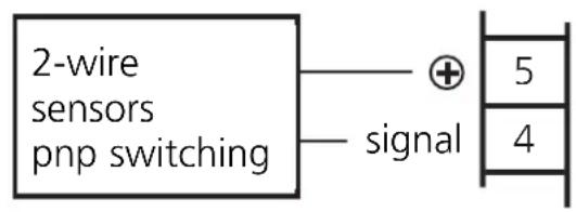
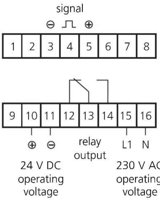
Wiring diagram
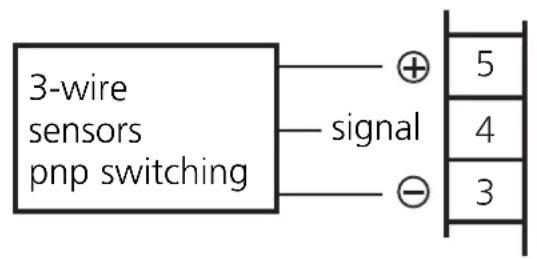
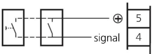
mechanical contacts or switches
Operating elements and indicators
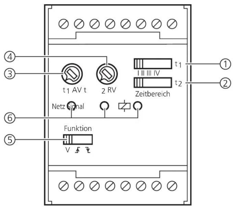
| 1 Selector switch for the time ranges with ON delay (AV) | |
| 2 Selector switch for the time ranges with OFF delay (RV) and fleeting pulse | |
| 3 Pot for the fine setting of the ON delay time | |
| 4 Pot for the fine setting of the OFF delay time and the fleeting pulse | |
| 5 Selector switch for: ON delay and/or OFF delay ON pulse OFF pulse | |
| 6 LEDs for: Netz Signal Switching state green |
Setting of the functions and time
| Function | Switch | Switch time range Pot | |||||
| Function V | t1 I II III IV | t2 I II III IV | t1AV t2RV | ||||
| ON delay | |||||||
| OFF delay | |||||||
| ON + OFF delay | |||||||
| ON pulse | |||||||
| OFF pulse | |||||||
| Delayed ON pulse | |||||||
| Delayed OFF pulse | |||||||
| Legend | Selector switch position | ||||||
| AV=ON delay | Potentiometer set for delay chosen | ||||||
| RV=OFF delay | Potentiometer set to left stop position | ||||||
Time ranges
There is one time range available for the ON delay and one for the OFF delay. The entire time ranges of 0.25 to 640 seconds are divided into four individual ranges which can be set with a switch.
| Position Time range switch (t1/t2) [seconds] | |
| I 0,25...2,50 | |
| II 1...10 | |
| III 8...80 | |
| IV 64...640 |
Setting of the time
After preselection of the time range the time is set with the corresponding pot. This scale is divided by percentage of the time range end value (10...100%).
| Pot (t1/t2) Time [%] [approx. | seconds] | |||
| I | III | IV | ||
| 10 | 0.25 | 1 | 8 | 64 |
| 20 | 0.50 | 2 | 16 | 128 |
| 30 | 0.75 | 3 | 24 | 192 |
| 40 | 1.00 | 4 | 32 | 256 |
| 50 | 1.25 | 5 | 40 | 320 |
| 60 | 1.50 | 6 | 48 | 384 |
| 70 | 1.75 | 7 | 56 | 448 |
| 80 | 2.00 | 8 | 64 | 512 |
| 90 | 2.25 | 9 | 72 | 576 |
| 100 | 2.50 | 10 | 80 | 640 |
Function
Input
(tmin:300ms)
Output
(t1)
ON delay
(t2)
OFF delay
ON + OFF
delay
ON pulse
OFF pulse
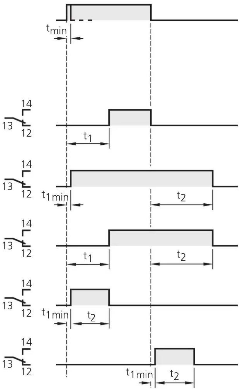
t1min: >250~ms < 300ms
The start of the fleeting pulse can be delayed with t_1 .
Technical data (at +20^ )
| Housing plastic, with 16 connection terminals, corresponding to the regulations of the engineering and automotive industry | |
| Protection rating housing IP | 40, terminals IP 20 |
| Ambient temperature 0...55 °C | °C |
| Operating voltage 230 V AC | ± 10 %, 50...60 Hz 24 V DC, ± 10 % |
| Auxiliary power for sensor or mechanical contact over | 24 V DC, ± 5 %, stabilised, 40 mA oad and short-circuit-protection for 15 min |
| Input level "High" at > 15 | V, ≥7 mA "Low" at < 5 V, ≤2 mA |
| Switching output potential | free, 1 x 1 changeover contact switching power 1250 VA, max. switching voltage 250 V, max. switching current 8 A AC, max. |
| Repeatability ≤3 % of the set value, over the hole temperature range | |
Terminal connection
Généralité
Brand : IFM
Model : DT0001
Category : Electrical relay