O3M271 - Sensor IFM - Free user manual and instructions
Find the device manual for free O3M271 IFM in PDF.


User questions about O3M271 IFM
0 question about this device. Answer the ones you know or ask your own.
Ask a new question about this device
Download the instructions for your Sensor in PDF format for free! Find your manual O3M271 - IFM and take your electronic device back in hand. On this page are published all the documents necessary for the use of your device. O3M271 by IFM.
USER MANUAL O3M271 IFM
Operating instructions
Mobile 3D (smart) sensor / camera
O3M1xx
O3M2xx
Contents
1 Preliminary note 3
1.1 Symbols used 3
1.2 Warnings.... 3
1.3 Safety symbols on the unit 3
1.4 Legal and copyright information 3
2 Safety instructions.... 5
2.1 Cyber security 5
3 Functions and features 6
3.1 Application area 6
4 Installation.... 7
4.1 Mounting accessories 7
5 Electrical connection.... 8
5.1 Wiring example 9
5.2 Wiring, rear 10
5.2.1 CAN bus 10
5.2.2 Ethernet 11
5.3 Wiring, bottom.... 11
5.3.1 Analogue video output (PAL) 12
6 Installation.... 13
7 Set-up.... 14
7.1 Changing the operation principle.... 15
8 Approvals/standards 16
9 Maintenance, repair and disposal 17
1 Preliminary note
You will find instructions, technical data, approvals and further information using the QR code on the unit / packaging or at documentation.ifm.com.
1.1 Symbols used
√ Requirement
Instructions
Reaction, result
[...] Designation of keys, buttons or indications
→ Cross-reference

Important note
Non-compliance may result in malfunction or interference.

Information
Supplementary note
1.2 Warnings
Warnings indicate the possibility of personal injury and damage to property. This enables safe product handling. Warnings are graded as follows:

WARNING
Warning of serious personal injury
▷ If the warning is not observed, fatal and serious injuries are possible.

CAUTION
Warning of minor to moderate personal injury
▷ If the warning is not observed, minor to moderate injuries are possible.
ATTENTION
Warning of damage to property
▷ If the warning is not observed, damage to property is possible.
1.3 Safety symbols on the unit

• Electric supply must correspond to IEC 61010-1, chapter 9.4 - Limited-energy circuit.
- The photobiological safety of devices with Risk Group 1 must be taken into consideration.

Device of protection class III. Only for operation in PELV circuits ( → chapter Electrical connection).
1.4 Legal and copyright information
© All rights reserved by ifm electronic gmbh. No part of these instructions may be reproduced and used without the consent of ifm electronic gmbh.
All product names, pictures, companies or other brands used on our pages are the property of the respective rights owners.
2 Safety instructions
- The unit described is a subcomponent for integration into a system.
- The system architect is responsible for the safety of the system.
-
The system architect undertakes to perform a risk assessment and to create documentation in accordance with legal and normative requirements to be provided to the operator and user of the system. This documentation must contain all necessary information and safety instructions for the operator, the user and, if applicable, for any service personnel authorised by the architect of the system.
-
Read this document before setting up the product and keep it during the entire service life.
- The product must be suitable for the corresponding applications and environmental conditions without any restrictions.
- Only use the product for its intended purpose (→ Intended use).
- If the operating instructions or the technical data are not adhered to, personal injury and/or damage to property may occur.
- The manufacturer assumes no liability or warranty for any consequences caused by tampering with the product or incorrect use by the operator.
- Installation, electrical connection, set-up, operation and maintenance of the product must be carried out by qualified personnel authorised by the machine operator.
- Protect units and cables against damage.
2.1 Cyber security
ATTENTION
Unprotected network environment.
The device does not include IT security measures according to IEC 62443.
▷ Unauthorised read or write access to data is possible.
▷ Unauthorised manipulation of the device function is possible.
▶ Check and restrict access options to the device.
3 Functions and features
The mobile 3D smart sensor / camera is a photoelectric sensor (hereinafter referred to as “device”). The device measures the distance to the nearest surface point by point.
The device is operated as a system together with an illumination unit. The illumination unit illuminates the scene and the device processes the light reflected by the surface.
The processed data is used to describe the captured scene three-dimensionally. The data is provided via Ethernet. The device parameters are set via the CAN interface.

The device must not be used if it
▶ has fallen to the floor in its original packaging from a height of ≥ 1 m,
▶ shows visible damage.
3.1 Application area
Permitted application area:
- on mobile machines with supply from on-board systems (with battery) of 12 V DC or 24 V DC nominal voltage
• in an industrial environment with supply from SELV/PELV according to the technical data
• in outdoor applications
The device safety is rated for use under the following operating conditions according to EN IEC 61010-2-201:
• altitudes up to 4000 m
• relative air humidity up to max. 90 %, non condensing
- pollution degree 4

The unit is not approved for safety-related tasks in the field of operator protection.

Electromagnetic compatibility (EMC):
The unit is designed for use in industrial environments.
This product may cause radio interference in domestic areas.
▶ If required, take appropriate EMC screening measures.
4 Installation
The device is operated as a system together with the illumination unit.
During installation note the following:
▶ Operate the device and the illumination unit in combination.

Fig. 1: Combination of the device and the illumination unit
▶ Install the device and the illumination unit between 0 and 2.80 m apart.
▷ Select the matching MCI connection cable depending on the distance.
▶ Use suitable brackets for the application.
▶ Keep the area illuminated by the illumination unit free from any obstructions in a close range (up to 50 cm) (see figure below).
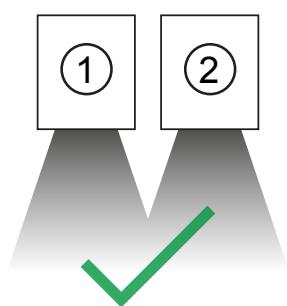

Fig. 2: Avoid obstructions in a close range
1 Device
2 Illumination unit
4.1 Mounting accessories
Depending on the intended mounting location and the type of installation, the following mounting accessories are available:
| Article number | Description |
| E3M100 | Mounting bracket for O3 Mxxx (sensor and illumination unit)U-shaped, silver, adjustable |
| E3M102 | Mounting bracket for O3 Mxxx (sensor and illumination unit)U-shaped, black, adjustable |
5 Electrical connection
The device must be connected by a qualified electrician.
▶ Disconnect power before connecting the device.

Protection class III (PC III) device (IEC 61010-2-201 chap. 6.5.2.101.4).
The electrical supply must
• be provided only by PELV circuits (IEC 61010-2-201 chap. 3.111),
• not exceed 35 V DC during operation,
• not exceed 60 V DC in the event of a single fault and
• not exceed the permitted operating voltage of the device (see data sheet).
The separation of external circuits must comply with IEC 61010-2-201, Figure 102.
ATTENTION
No suitable energy limitation of the circuit
▷ Fire hazard in case of a malfunction.
▶ Use energy-limited circuit according to IEC 61010-1 chap. 9.4.
The energy of the circuit can be limited by an overcurrent protection device:
| Designation | Voltage | Nominal value fuse | Tripping characteristics |
| VBB | 9..16 V | 5 A | Tfuse < 120 s at max. 10 A |
| VBB | 16..32 V | 3 A | Tfuse < 120 s at max. 6.25 A |
Observe the specific tripping characteristic. Possible overcurrent protection devices:
- fuse or
• non-adjustable and non-self-reclosing electromechanical device.
For the correct rating of the overcurrent protection device take the technical data of the device and wiring into account. Separate the circuit from other, non-energy-limited circuits by at least basic insulation.
ATTENTION
Use an additional protection against surge voltages according to IEC 61000-4-5 if the connection cable is longer than 30 m.
ATTENTION
The device can be damaged by insufficiently tightened M12 connectors.
▷ The IP protection rating indicated in the data sheet is only guaranteed if the M12 connectors are firmly screwed.
▶ Firmly screw the M12 connectors to the device.
▶ Cover the unused sockets with the pre-mounted protective caps. Tightening torque: 0.6...0.8 Nm.
▷ The protective cap for the Ethernet socket of the sensor can be reordered: article number ZJF051.
▶ Use strain reliefs for cables connected to the device.
ATTENTION
Device damaged due to short circuit
The following connections are unprotected in the event of a short circuit:
- between power supply and CAN bus,
- between power supply and Ethernet.
▶ Check the connections of the connection cables before activating the power supply.
Laying connection cables
Observe the following notes when laying the connection cables:
▶ Route the connection cables vertically or horizontally downwards away from the device.
▷ No liquid must accumulate on the sockets and connectors.
5.1 Wiring example

Fig. 3: Wiring example
1 Illumination unit
2 Device
3 PC
4 Power supply
5.2 Wiring, rear

Fig. 4: Connections on the rear
1 Power supply and CAN bus
3 MCI (Modulation and Communication Interface)
2 Ethernet
| (1) Power supply and CAN bus | |
| M12 connector, A-coded, 5 poles | |
| 2 15 3 4 | 1: Shield2: 9...32 V3: GND4: CAN high5: CAN low |
| (2) Ethernet | |
| M12 socket, D-coded, 4 poles, 100 Mbits/s | |
| 1 24 3S | 1: TD+2: RD+3: TD-4: RD-S: Shield |
| (3) MCI (Modulation and Communication Interface) |
| Connects the device and the illumination unit. |
5.2.1 CAN bus
The CAN bus is used for the following functions:
- sending/receiving function data (e.g. object list, virtual inputs and outputs etc.),
- parameter setting,
- diagnostics,
- firmware updates.

The CAN bus connection is not required for the operation of the device.

The CAN bus connection is almost trouble-free if the following points are considered:
▶ Use cables approved for CAN bus.
▶ Terminate the cables with 120 Ω terminating resistors.
5.2.2 Ethernet
Additional data is output via the Ethernet interface, for example the 3D data of the point cloud.
Preset IP address of the device: 192.168.1.1.
The user data is sent to all accessible participants via UDP broadcast.
Preset target IP address for the broadcast: 255.255.255.255, port 42000.
The Ethernet interface can be used with cables with two twisted pairs (e.g. Cat 5 cables).

Communication via Ethernet is unidirectional. The device is a transmitter only. The device cannot receive data via Ethernet.
5.3 Wiring, bottom

Fig. 5: Connections on the bottom
1 Analogue video output (PAL)
| (1) Analogue video output (PAL) | |
| M12 socket, A-coded, 5 poles | |
| 1: Shield3: GND4: FBAS (video) |

Only use the following ifm cables for the analogue video output:
▷ E3M151 (5 m, connection cable, angled connector)
E3M152 (11 m, connection cable, angled connector)
E3M153 (16 m, connection cable, angled connector)
E3M154 (21 m, connection cable, angled connector)
E3M159 (5 m, connection cable)
E3M160 (1 m, video adapter cable)

Only the O3M2xx devices have an additional analogue video output (PAL).
5.3.1 Analogue video output (PAL)
The O3M2xx devices have an additional analogue video output (PAL). The 2D image of the analogue video output can be displayed in the ifm Vision Assistant software using a video converter.

The video converter must support the following functions:
- PAL television standard,
- Microsoft DirectX.
6 Installation
The following articles are required for installing the device and setting its parameters:
| Article number | Description |
| E3D300 | ifm Vision Assistant software |
| EC2114 | Programming cable set for CAN interface |
| EC2112 | CAN interface for PC “CANFox” |
| Windows drivers for CANFox |
▶ Download the ifmVision
Assistant software via the download area of the unit: documentation.ifm.com
▶ Download the Windows drivers for CANFox via the download area of the article EC2112: documentation.ifm.com

The operation of the ifm Vision Assistant software is described in the software manual.
▶ Download the software manual via the download area of the device: documentation.ifm.com
7 Set-up
The following articles are required for setting up the device:
| Article number | Versions | Description |
| O3M950 (for O3Mx51) | O3M960 (for O3Mx61)O3M970 (for O3Mx71) | Illumination unit The device is operated in combination with an illumination unit. |
The following cables, for example, can be used for set-up:
| Article number | Versions | Description |
| E3M131 (2 m) | E3M132 (5 m)E3M133 (10 m) | Power supply cable for illumination unit |
| E3M120 (0.5 m) | E3M124 (2 m) | MCI connection cable with angled socket |
| E3M121 (1 m) | E3M122 (2 m)E3M123 (3 m) | MCI connection cable |
| E11596 (2 m) | E11597 (5 m)EVC492 (5 m, with terminating resistor)EVC683 (10 m, with terminating resistor) | Connection cable for CAN bus and power supply |
| E3M151 (5 m) | E3M152 (11 m)E3M153 (16 m)E3M154 (21 m) | Connection cable with angled connector for analogue video output of O3M2x1 |
| E3M159 (5 m) | Connection cable without angled connector for analogue video output of O3M2x1 | |
| E3M160 (1 m) | Video adapter cable | |
| EVC924 (0,5 m) | EVC925 (1 m)EVC936 (3 m)EVC928 (10 m) | Ethernet connection cable |
Putting the device into operation:
▶ Switch off the power supply.
▶ Connect the device to the illumination unit via an E3M121 "MCI connection cable".
▶ Connect the device to the PC via an EVC924 "Ethernet connection cable".
▶ Connect the device to the power supply via an E11596 “connection cable for CAN bus and power supply”.
▶ Connect the illumination unit to the power supply via an E3M131 "power supply cable".
▶ Connect the CANFox CAN interfaceto the PC via the USB port.
▶ Connect the CANFox CAN interface to the E11596 “Connection cable for CAN bus and power supply”.
▶ Only for O3M2xx devices: Connect the device to a video converter, display etc. via an E3M151 "Connection cable for analogue video output".
▶ Activate the power supply.

During the first set-up the device connects with the illumination unit. Connection may take up to 60 s.
Afterwards the device can be configured via the ifm Vision Assistant software. (→ Installation ☐ 13)

Error messages when setting the 3D sensor parameters
▷ The 3D sensor O3M1xx/2xx must be connected to the O3M9xx illumination unit for parameter setting. If the 3D sensor is not connected to the illumination unit, parameter setting will be aborted with error messages.
▶ Only use the 3D sensor in conjunction with the illumination unit.
7.1 Changing the operation principle
The basic operation principle of the device can be changed by installing a different firmware on the device. The firmware “Distance Image” is pre-installed.
The following firmware is available:
| Firmware | Description |
| Distance Image | Distance image (3D point cloud), basic functions, regions of interest (ROI) |
| Object Detection | Object detection, collision avoidance, reflector tracing |
| Line Guidance | Windrow detection, line tracking, crop edge detection |
Installing the firmware:
▶ Download the firmware via the download area of the device: documentation.ifm.com
▶ Install the firmware via the ifm Vision Assistant software.
▷ The installation of the firmware is described in the software manual of the device: documentation.ifm.com
8 Approvals/standards
For approvals and standards, the following information is available:
• Test standards and regulations: documentation.ifm.com
• EU declaration of conformity and approvals: documentation.ifm.com
• Notes relevant for approval: Package insert of the device and documentation.ifm.com
9 Maintenance, repair and disposal
If used correctly, the unit is maintenance-free.
Soiling reduces the contrast and the recognition performance.
▶ Keep the front pane free from soiling.
▶ Use glass cleaner or isopropanol as a cleaning agent.
Only the manufacturer is allowed to repair the unit.
▶ After use, dispose of the unit in an environmentally friendly way in accordance with the applicable national regulations.
- 1 PRELIMINARY NOTE
- 1.1 SYMBOLS USED
- 1.2 WARNINGS
- 1.3 SAFETY SYMBOLS ON THE UNIT
- 1.4 LEGAL AND COPYRIGHT INFORMATION
- 2 SAFETY INSTRUCTIONS
- 2.1 CYBER SECURITY
- 3 FUNCTIONS AND FEATURES
- 3.1 APPLICATION AREA
- 4 INSTALLATION
- 4.1 MOUNTING ACCESSORIES
- 5 ELECTRICAL CONNECTION
- 5.1 WIRING EXAMPLE
- 5.2 WIRING, REAR
- 5.2.1 CAN BUS
- 5.2.2 ETHERNET
- 5.3 WIRING, BOTTOM
- 5.3.1 ANALOGUE VIDEO OUTPUT (PAL)
- 6 INSTALLATION
- 7 SET-UP
- 7.1 CHANGING THE OPERATION PRINCIPLE
- 8 APPROVALS/STANDARDS
- 9 MAINTENANCE, REPAIR AND DISPOSAL
Brand : IFM
Model : O3M271
Category : Sensor