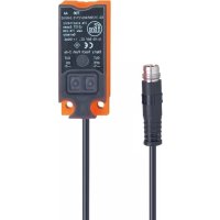
KQ6004 - Sensor IFM - Free user manual and instructions
Find the device manual for free KQ6004 IFM in PDF.


User questions about KQ6004 IFM
0 question about this device. Answer the ones you know or ask your own.
Ask a new question about this device
Download the instructions for your Sensor in PDF format for free! Find your manual KQ6004 - IFM and take your electronic device back in hand. On this page are published all the documents necessary for the use of your device. KQ6004 by IFM.
USER MANUAL KQ6004 IFM
Operating instructions
Capacitive sensor
KQ6xxx
Contents
1 Preliminary note.... 3
1.1 Symbols used.... 3
2 Safety instructions 4
2.1 Cybersecurity 4
3 Transport, handling and storage 5
4 Intended use 6
5 Function 7
5.1 IO-Link 7
6 Installation 8
6.1 Use for level monitoring 8
6.1.1 Installation on tanks with mounting adapter 8
6.1.1.1 Bore hole dimensions of the mounting adapter 9
6.1.2 Installation on bypass pipes with mounting adapter 9
6.2 Use for position detection 9
6.2.1 Installation and installation remarks 10
6.2.1.1 Minimum distances 10
6.3 Use without mounting adapter.... 11
6.3.1 Bore hole dimensions of the device 11
6.4 Notes on laying of the connection cable 11
7 Electrical connection 12
7.1 Device version with automatic load detection 12
8 Operating and display elements.... 13
9 Settings.... 14
9.1 Empty adjustment 14
9.2 Full adjustment.... 14
9.3 Modified empty adjustment.... 15
9.4 Button lock.... 16
10 Parameter setting 17
10.1 Teach.... 17
10.1.1 Empty adjustment 17
10.1.2 Full adjustment.... 17
10.1.3 Modified empty adjustment 17
10.2 Configuring parameters.... 18
11 Operation.... 20
12 Maintenance, repair and disposal 21
1 Preliminary note
You will find instructions, technical data, approvals, accessories and further information using the QR code on the device / packaging or at documentation.ifm.com.
1.1 Symbols used
√ Requirement
▶ Instruction
▷ Reaction, result
bold Designation of keys, buttons or indications
→ Cross-reference without link
→ Cross-reference with link


Important note
Non-compliance may result in malfunction or interference
Information
Supplementary note
2 Safety instructions
- The unit described is a subcomponent for integration into a system.
- The system architect is responsible for the safety of the system.
-
The system architect undertakes to perform a risk assessment and to create documentation in accordance with legal and normative requirements to be provided to the operator and user of the system. This documentation must contain all necessary information and safety instructions for the operator, the user and, if applicable, for any service personnel authorised by the architect of the system.
-
Read this document before setting up the product and keep it during the entire service life.
- The product must be suitable for the corresponding applications and environmental conditions without any restrictions.
- Only use the product for its intended purpose (→ Intended use).
- If the operating instructions or the technical data are not adhered to, personal injury and/or damage to property may occur.
- The manufacturer assumes no liability or warranty for any consequences caused by tampering with the product or incorrect use by the operator.
- Installation, electrical connection, set-up, operation and maintenance of the product must be carried out by qualified personnel authorised by the machine operator.
- Protect units and cables against damage.
2.1 Cybersecurity
Installation
The device is suitable for operation in a secure environment according to IEC 62443-1-1.
The device was designed for operation behind a firewall.
▶ Carry out a risk assessment of the system according to IEC 62443-1-1.
▶ Take measures to ensure physical security.
Operation
▶ Observe the security functions described in the product documentation and the recommendations for their use.
Maintenance
▶ Back up system configuration and system data in accordance with your company's change management processes.
Decommissioning
▶ Ensure that no sensitive information can fall into unauthorised hands.
▶ Always reset the system settings to the factory settings before decommissioning the device.
3 Transport, handling and storage
▶ Store the device in its original packaging.
▶ When the device is to be stored again, use the original packaging.
▶ Otherwise, provide unused connections with either a mating connector or a protective cap and pack the device in suitable packaging.
▶ Observe the permissible ambient conditions for the device during storage (→ Technical data).
4 Intended use
The unit detects without contact metals, almost all plastics, glass, ceramics, wood, paper, oils, greases, water and all hydrous materials and indicates their presence by a switching signal.
The device detects the medium through the tank wall. The wall is suppressed by means of an adjustment function, so that only the medium is detected.

The tank wall must be made of a non-metal material.
5 Function
The device detects position and level according to the capacitive measuring principle.
The device has 2 programming buttons.
The device has an IO-Link interface.
Setting options via the IO-Link interface:
- Switch point logic (normally closed/normally open)
- Switch point (SP1)
- Hysteresis
- Start-up delay
- Output delay
- Damping
- Button lock
Visualisation of the switch points via LED display: → Operating and display elements.
5.1 IO-Link
IO-Link is a communication system for connecting intelligent sensors and actuators to automation systems. IO-Link is standardised in the IEC 61131-9 standard.

General information on IO-Link at io-link.ifm

Input Output Device Description (IODD) with all parameters, process data and detailed descriptions of the device at documentation.ifm.com
IO-Link offers the following advantages:
• Interference-free transmission of all data and process values
• Parameter setting in the running process or presetting outside the application
• Parameters for identifying the connected devices in the system
• Additional parameters and diagnostic functions
• Automatic backup and restore of parameter sets in case of device replacement (data storage)
• Logging of parameter sets, process values and events
• Device description file (IODD - Input Output Device Description) for easy project planning
• Standardised electrical connection
• Remote maintenance
6 Installation
6.1 Use for level monitoring
The device can be installed on tanks or bypass pipes to monitor levels.
6.1.1 Installation on tanks with mounting adapter
The mounting adapter E12153 must be ordered separately.
▶ Insert the lower part of the device (1) into the mounting adapter. The sockets of the mounting adapter must engage in the cut-outs at the bottom of the device (A).
▶ Press the lower part of the device against the adapter.
▶ Press the device completely into the mounting adapter (2).
▷ The device audibly clips into place.
▶ Fasten the device to the mounting adapter using the fixing screws (3) provided (B).
▶ Fasten the mounting adapter including the inserted device to the tank at the required height using suitable fixing screws (4) (C).


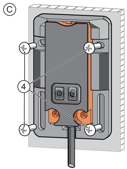
Fig. 1: Installation on tanks with mounting adapter

▶ Do not place the mounting adapter including the inserted device in the immediate vicinity of metal objects.
6.1.1.1 Bore hole dimensions of the mounting adapter
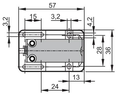
Fig. 2: Bore holes of the mounting adapter
6.1.2 Installation on bypass pipes with mounting adapter
The mounting adapter E12163 must be ordered separately.
▶ Fasten the device to the bypass pipe at the required height using cable ties (E10880) (A).
▶ Pass the cable ties through the mounting holes of the mounting adapter and tighten them securely (B).
A
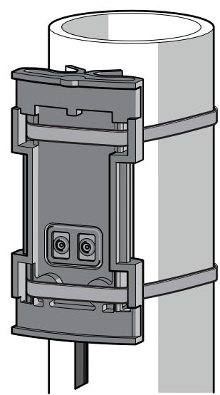
B

Fig. 3: Installation on bypass pipes with mounting adapter
6.2 Use for position detection
The device can be used to detect objects approaching laterally, for example.
6.2.1 Installation and installation remarks
without mounting adapter

with mounting adapter
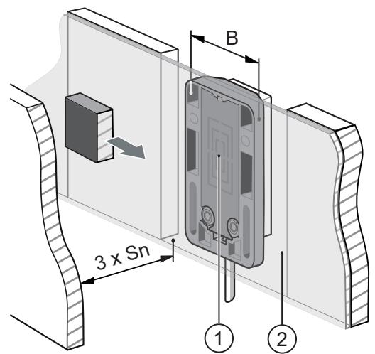
Fig. 4: Installation and installation remarks
1: Sensing face
A: Distance = 8 mm
2: Plastic plate
B: Width of the mounting adapter = 36 mm
Sn : Nominal sensing range → data sheet
▶ Align the sensing face (1) to the object.
▶ Adhere to the indicated minimum distances to metallic objects opposite and beside the sensor (free space).
▷ Non-metallic objects (e.g. plastic fixtures) are allowed within the lateral free space.
▶ Fasten the device to the designated location using suitable fixing screws.
▶ When installed behind a plastic plate (2), the object will be detected through the wall.

Depending on the material used and the wall thickness the device characteristics might change slightly.
▶ Do not use conductive plastics.
▶ If possible, use thin walls.
6.2.1.1 Minimum distances
Installing several devices of the same type
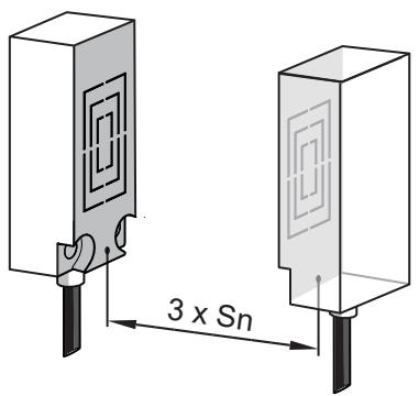
Fig. 5: Minimum distances
Sn : Nominal sensing range → data sheet
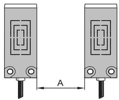
A: Distance between the devices 50 mm
6.3 Use without mounting adapter
A

B
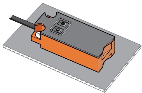
Fig. 6: Installation without mounting adapter
▶ Fasten the device to the designated location using suitable fixing screws or suitable glue.
▶ Align the cut-outs as shown.
6.3.1 Bore hole dimensions of the device
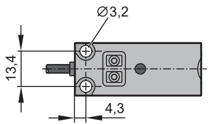
Fig. 7: Bore holes of the device
6.4 Notes on laying of the connection cable
▶ Lay the cable as straight as possible and do not coil it.
▶ If necessary, cut the cable to the required length.
7 Electrical connection

The unit must be connected by a qualified electrician.
▶ Observe the national and international regulations for the installation of electrical equipment.
▶ Disconnect power.
▶ Connect the unit as follows:


Fig. 8: PNP wiring (types ...FPKG... or ...FPOG...)

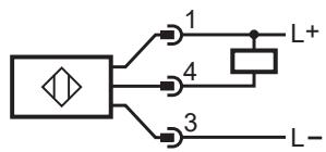
Fig. 9: NPN wiring (types ...FNKG... or ...FNOG...)
| BN: | Brown | 1: | L+ |
| BK: | Black | 3: | L- |
| BU: | Blue | 4: | OUT1/IO-Link |
7.1 Device version with automatic load detection
On power up, device types with automatic load detection (types ...FAKG... or ...FAOG...) detect automatically if the output is connected to L- (p switching) or to L+ (n switching).
▶ Disconnect the power supply after changing the load connection.

Automatic load detection is only ensured when a resistor is switched in series to a closed mechanical contact.
8 Operating and display elements
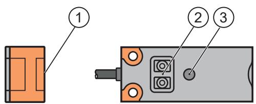
Fig. 10: Operating and display elements
1: Sensing face
2: Programming buttons
3: LED
9 Settings
9.1 Empty adjustment
By carrying out an empty adjustment, the device suppresses the installation environment. The empty adjustment resets the device; any adjustment that has already been performed will be deleted.
Setting operation:
▶ Empty the tank until the level is at least 20 mm below the device (A).
Set the device to normally open (output closes when the tank is full):
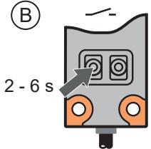
▶ Press OUT OFF for min. 2 s (max. 6 s) (B).
▷ While pressing the pushbutton, the LED flashes slowly.
▷ After releasing the pushbutton, the LED goes out.
Set the device to normally closed (output opens when the tank is full):
▶ Press OUT ON for min. 2 s (max. 6 s) (B).
▷ While pressing the pushbutton, the LED flashes slowly.
▷ After releasing the pushbutton, the LED lights continuously.
A

B
C
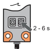
Fig. 11: Empty adjustment
The device is now ready for operation. For the detection of media with a low dielectric constant (e.g. plastic granulates or oils) no further setting is required.
9.2 Full adjustment
A full adjustment is necessary for aqueous media. The sensitivity of the device is optimised. The full adjustment can be repeated at any time, an empty adjustment already carried out will not be affected.

An empty adjustment must be carried out prior to the full adjustment.
▷ If it is not possible to empty the tank, an empty adjustment can be carried out by simulating the empty state (e.g. adjustment when not installed, adjustment at a higher position). For optimum function it is necessary to carry out a modified empty adjustment when the tank is emptied the next time.
Setting operation:
▶ Fill the tank until the sensing face of the device is covered (A).
▷ For NO the LED lights.
▷ For NC the LED goes out.
Set the device as normally open (output closes when the tank is full):
▶ Press OUT ON for min. 6 s (B).
▷ While pressing the pushbutton, the LED first flashes slowly, after 6 s more quickly.
▷ After releasing the pushbutton, the LED lights continuously.
Set the device as normally closed (output opens when the tank is full):
▶ Press OUT OFF for min. 6 s (C).
▷ While pressing the pushbutton, the LED first flashes slowly, after 6 s more quickly.
▷ After releasing the pushbutton, the LED goes out.
A
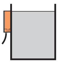
B
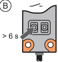
C
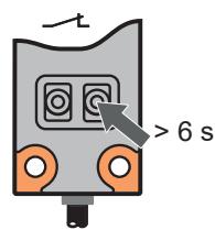
Fig. 12: Full adjustment
9.3 Modified empty adjustment
A modified empty adjustment is recommended in the following cases:
- In case of deposits in the tank (these can be largely suppressed when using the modified empty adjustment).
• If no proper empty adjustment could be carried out.
Later on, the modified empty adjustment can be repeated at any time, a full adjustment already carried out will not be affected.
Setting operation:
▶ Empty the tank until the level is below the sensing face of the device (A).
▷ For NO the LED goes out.
▷ For NC the LED lights.
Set the device as normally open (output closes when the tank is full):
▶ Press OUT OFF for min. 6 s (B).
▷ While pressing the pushbutton, the LED first flashes slowly, after 6 s more quickly.
▷ After releasing the pushbutton, the LED goes out.
Set the device as normally closed (output opens when the tank is full):
▶ Press OUT ON for min. 6 s (C).
▷ While pressing the pushbutton, the LED first flashes slowly, after 6 s more quickly.
▷ After releasing the pushbutton, the LED lights.
A

B

C

Fig. 13: Modified empty adjustment
9.4 Button lock
The device can be locked electronically to prevent unauthorised setting.
▶ To lock, press OUT ON and OUT OFF simultaneously for 10 seconds.
▷ The LED state changes for a short time (the lit LED goes out briefly or the LED which is not lit lights briefly).
▶ To unlock repeat this step.

Fig. 14: Lock /unlock
If the device does not react, it may be locked.
The button lock can also be set via IO-Link. ➕ 19
10 Parameter setting
The device provides a digital switching signal via a switching signal channel (SSC = Switching Signal Channel).
The switching signal channel can only be read via the IO-Link interface.
Logic
By setting the logic High active or Low active, you can specify which value the switching signal channel has in the active state:
- High active: The switching signal channel is “high” in the active state (= ON = normally open = 1)
- Low active: The switching signal channel is "low" in the active state (= OFF = normally closed = 0)
10.1 Teach
10.1.1 Empty adjustment
By carrying out an empty adjustment, the device suppresses the installation environment. The empty adjustment resets the device; any adjustment that has already been performed will be deleted.
Parameter setting:
▶ Empty the tank until the level is at least 20 mm below the device.
▶ Call up Parameters > Teach.
▶ Execute the command: Teach empty state.
The device is now ready for operation. For the detection of media with a low dielectric constant (e.g. plastic granulates or oils) no further setting is required.
10.1.2 Full adjustment
A full adjustment is necessary for aqueous media. The sensitivity of the device is optimised. The full adjustment can be repeated at any time, an empty adjustment already carried out will not be affected.

An empty adjustment must be carried out prior to the full adjustment.
▷ If it is not possible to empty the tank, an empty adjustment can be carried out by simulating the empty state (e.g. adjustment when not installed, adjustment at a higher position). For optimum function it is necessary to carry out a modified empty adjustment when the tank is emptied the next time.
Parameter setting:
▶ Fill the tank until the sensing face of the device is covered.
▶ Call up Parameters > Teach.
▶ Execute the command: Teach full state.
10.1.3 Modified empty adjustment
A modified empty adjustment is recommended in the following cases:
- In case of deposits in the tank (these can be largely suppressed when using the modified empty adjustment).
• If no proper empty adjustment could be carried out.
Later on, the modified empty adjustment can be repeated at any time, a full adjustment already carried out will not be affected.
Parameter setting:
▶ Empty the tank until the level is below the sensing face of the device.
▶ Call up Parameters > Teach.
▶ Execute the command: Adjustment teach empty state.
10.2 Configuring parameters
10.2.1 Switch point 1
▶ Call up Parameters > Switchpoint configuration.
▶ Select and set SP.Switch point 1:
• value range 6...1645
10.2.2 Switch point logic
▶ Call up Parameters > Switchpoint configuration.
▶ Select and setSP.Switchpoint logic:
- normally open
- normally closed
10.2.3 Hysteresis
▶ Call up Parameters > Switchpoint configuration.
▶ Select and set SP.Switchpoint hysteresis:
• value range 6...1645
10.2.4 Start-up delay
▶ Call up Parameters > Switchpoint configuration > Delay time.
▶ Select and set dS:
• value range from 0...3600 s
10.2.5 Switch-off delay
▶ Call up Parameters > Switchpoint configuration > Delay time.
▶ Select and set dr:
• value range from 0...3600 s
10.2.6 Damping
▶ Call up Parameter > Damping.
▶ Select and set dAP:
• value range = 0...2000 ms
10.2.7 Restore factory settings
▶ Call up Parameter > Setup.
▶ Click on the system command Restore factory settings.
▷ The device carries out a reboot.
10.2.8 Device access locks.Data storage
This lock prevents write access to device parameters.
▶ Make sure that the device is in the normal operating mode.
▶ Call up Parameter > Setup.
▶ Select and set Device access locks.Data storage:
- Locked
- Unlocked (factory setting)
10.2.9 Device access locks.Local parameterization
This lock prevents the settings from being changed via the local operating elements on the device. The lock can only be configured via IO-Link.
▶ Call up Parameter > Setup.
▶ Select and set Device access locks. Local parameterization:
- Locked
- Unlocked (factory setting)
10.2.10 Button lock
This lock prevents the settings from being changed via the local operating elements on the device.
▶ Call up Parameter > Setup.
▶ Select and set Keylock:
- active
• inactive (factory setting)
The button lock can also be set via the device keys. ➞ 16
11 Operation
▶ Check whether the unit operates correctly.
▶ Bring about a unit response by taking suitable measures.
LED display
LED yellow out: switching output disabled
LED yellow ON: switching output enabled
12 Maintenance, repair and disposal
The operation of the unit is maintenance-free.
To ensure correct functioning, please note the following:
▶ Keep the sensing face and any clear spaces free from deposits and foreign bodies.
It is not possible to repair the unit.
After use dispose of the device in an environmentally friendly way in accordance with the applicable national regulations.
- CONTENTS
- 1 PRELIMINARY NOTE
- 1.1 SYMBOLS USED
- 2 SAFETY INSTRUCTIONS
- 2.1 CYBERSECURITY
- INSTALLATION
- OPERATION
- MAINTENANCE
- DECOMMISSIONING
- 3 TRANSPORT, HANDLING AND STORAGE
- 4 INTENDED USE
- 5 FUNCTION
- 5.1 IO-LINK
- 6 INSTALLATION
- 6.1 USE FOR LEVEL MONITORING
- 6.1.1 INSTALLATION ON TANKS WITH MOUNTING ADAPTER
- 6.1.1.1 BORE HOLE DIMENSIONS OF THE MOUNTING ADAPTER
- 6.1.2 INSTALLATION ON BYPASS PIPES WITH MOUNTING ADAPTER
- 6.2 USE FOR POSITION DETECTION
- 6.2.1 INSTALLATION AND INSTALLATION REMARKS
- 6.2.1.1 MINIMUM DISTANCES
- 6.3 USE WITHOUT MOUNTING ADAPTER
- 6.3.1 BORE HOLE DIMENSIONS OF THE DEVICE
- 6.4 NOTES ON LAYING OF THE CONNECTION CABLE
- 7 ELECTRICAL CONNECTION
- 7.1 DEVICE VERSION WITH AUTOMATIC LOAD DETECTION
- 8 OPERATING AND DISPLAY ELEMENTS
- 9 SETTINGS
- 9.1 EMPTY ADJUSTMENT
- SETTING OPERATION
- SET THE DEVICE TO NORMALLY OPEN (OUTPUT CLOSES WHEN THE TANK IS FULL)
- SET THE DEVICE TO NORMALLY CLOSED (OUTPUT OPENS WHEN THE TANK IS FULL)
- 9.2 FULL ADJUSTMENT
- SET THE DEVICE AS NORMALLY OPEN (OUTPUT CLOSES WHEN THE TANK IS FULL)
- 9.3 MODIFIED EMPTY ADJUSTMENT
- 9.4 BUTTON LOCK
- 10 PARAMETER SETTING
- LOGIC
- 10.1 TEACH
- 10.1.1 EMPTY ADJUSTMENT
- PARAMETER SETTING
- 10.1.2 FULL ADJUSTMENT
- 10.1.3 MODIFIED EMPTY ADJUSTMENT
- 10.2 CONFIGURING PARAMETERS
- 10.2.1 SWITCH POINT 1
- 10.2.2 SWITCH POINT LOGIC
- 10.2.3 HYSTERESIS
- 10.2.4 START-UP DELAY
- 10.2.5 SWITCH-OFF DELAY
- 10.2.6 DAMPING
- 10.2.7 RESTORE FACTORY SETTINGS
- 10.2.8 DEVICE ACCESS LOCKS.DATA STORAGE
- 10.2.9 DEVICE ACCESS LOCKS.LOCAL PARAMETERIZATION
- 10.2.10 BUTTON LOCK
- 11 OPERATION
- LED DISPLAY
- 12 MAINTENANCE, REPAIR AND DISPOSAL
Brand : IFM
Model : KQ6004
Category : Sensor