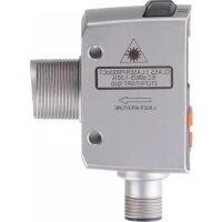
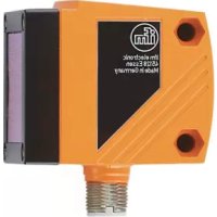
OGD583 - Rangefinder IFM - Free user manual and instructions
Find the device manual for free OGD583 IFM in PDF.


User questions about OGD583 IFM
0 question about this device. Answer the ones you know or ask your own.
Ask a new question about this device
Download the instructions for your Rangefinder in PDF format for free! Find your manual OGD583 - IFM and take your electronic device back in hand. On this page are published all the documents necessary for the use of your device. OGD583 by IFM.
USER MANUAL OGD583 IFM
CE
Operating instructions
Photoelectric distance sensor
OGD582
OGD583
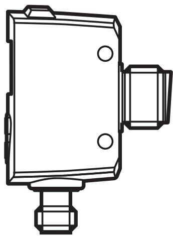
Contents
1 Preliminary note....4
1.1 Symbols used ....4
1.2 Warnings used....4
2 Safety instructions ....4
3 Functions and features .... 5
3.1 General notes 5
3.2 Applications ......6
3.3 Installation instructions ....6
3.3.1 Avoidance of soiling and ambient light 6
3.3.2 Avoidance of mutual interference 6
3.3.3 Sensor alignment to moving objects....7
4 Functions....7
4.1 Output function hysteresis....7
4.2 Output function window 8
4.3 Switch off the laser 8
4.4 Logic operator of the switching outputs 8
5 Installation....9
5.1 Installation conditions 9
5.2 Mounting accessories....9
6 Electrical connection....9
6.1 Operation with IO-Link master....10
7 Operating and display elements 10
7.1 Meaning of the display colours .... 11
7.1.1 Use of the display colours in the menu.... 11
8 Menu....12
8.1 Menu structure for window function....12
8.2 Menu structure for hysteresis function....13
8.3 Explanation of the menu....14
9 Operating modes 16
9.1 Run mode 16
9.2 Display mode....17
9.3 Programming mode 17
10 Parameter setting .... 17
10.1 General parameter setting....17
10.1.1 Set a parameter value .... 17
10.1.2 Change from menu level 1 to menu level 2....18
10.1.3 Electronic lock 19
10.2 Configuration of the basic settings .... 19
10.2.1 Configure OUT1 / OUT2....19
10.2.2 Hysteresis function for OUT1 20
10.2.3 Dynamic hysteresis 21
10.2.4 Hysteresis function for OUT2 21
10.2.5 Set the switch point for the hysteresis function OUT1 /OUT2 ......22
10.2.6 Window function for OUT1 23
10.2.7 Window function for OUT2 24
10.2.8 Set the switch points for window function OUT1 /OUT2....25
10.3 Extended functions 25
10.3.1 Set the display 25
10.3.2 Set background teach for hysteresis function OUT1 / OUT2 .....25
10.3.3 Teach the switch point for window function OUT1 / OUT2 ......26
10.3.4 Set switching hysteresis level for OUT2....26
10.3.5 Set the logic function for switching outputs 27
10.3.6 Set the delay time for switching outputs....27
10.3.7 Set the fault suppression time 27
10.3.8 Reset all parameters to factory setting....28
11 IO-Link 28
11.1 General information ....28
11.2 Device-specific information....28
11.3 Parameter setting tools....28
11.4 Functions ......28
12 Set-up / Operation 28
12.1 Error indications....29
12.1.1 Error indications for OUT1....29
12.1.2 Error displays for OUT2....29
13 Maintenance, repair, disposal 30
14 Scale drawing....30
15 Factory setting ....31
1 Preliminary note
1.1 Symbols used
▶ Instruction
▷ Reaction, result
[...] Designation of keys, buttons or indications
→ Cross-reference

Important note
Non-compliance may result in malfunction or interference.

Information
Supplementary note.
1.2 Warnings used

WARNING
Warning of serious personal injury.
Death or serious irreversible injuries may result.
2 Safety instructions
- Please read this document prior to set-up of the unit. Ensure that the product is suitable for your application without any restrictions.
- Improper or non-intended use may lead to malfunctions of the unit or to unwanted effects in your application. That is why installation, electrical connection, set-up, operation and maintenance of the unit must be carried out by qualified personnel authorised by the plant operator.
- In case of malfunction of the unit please contact the manufacturer. If the unit is tampered with and/or modified, any liability and warranty is excluded.

Caution - Use of controls or adjustments or procedures other than those specified herein may result in hazardous radiation exposure.
Position of the product label
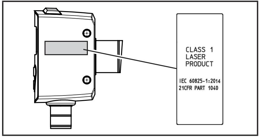
Warning sign

3 Functions and features
3.1 General notes
The unit is used as a photoelectric distance sensor.
The unit continuously detects the distance to the object and the reflectivity of the object and generates output signals according to the parameter settings.
- 2 switching outputs are available. They can be set separately. Switch points can either be set or taught.
- The measured values are shown in a 7-segment display and transferred via IO-Link. Two measured values are generated.
Measured distance value:
Distance from the front lens of the sensor to the target.
With the basic setting, the status of switching output OUT1 (pin 4) is determined from this measured value.
Object reflectivity:
Reflexivity of the target.
With the basic setting, the status of switching output OUT2 (pin 2) is determined from this measured value.
The unit uses a laser diode as light source and creates a light spot. This makes it possible to detect small objects.

The light spot should hit the object or the background. Intermediate states may lead to faulty measured values.
3.2 Applications
- The photoelectric distance sensor measures distances between 8...165 cm and object reflectivities between 0...999 %.
- It has a background suppression of up to 20 m.

The distance between the sensor and the background must be limited to max. 20 m. Otherwise measured values can be ambiguous → 5.1.
3.3 Installation instructions
3.3.1 Avoidance of soiling and ambient light
Preferably align photoelectric sensors with the front lens facing downwards or parallel to the earth's surface.
Background:
- Photoelectric sensors are sensitive to direct radiation of light sources. Everyday light sources (lamps, sun) radiate from above.
• Photoelectric sensors react sensitively to soiling, as it reduces the excess gain.

Dust deposits can be reduced by downwards or sideways orientation. This allows for longer cleaning intervals.

Make sure that sensors installed with their front lens facing upwards are not oriented towards roof windows or ceiling lamps.
3.3.2 Avoidance of mutual interference
Photoelectric sensors should be installed with a sufficient distance between each other. This particularly applies if the detection range of the two sensors partly intersects.
Background:
- Both sensors have a detection range. This means that the laser light spot of a sensor can be received by its neighbouring sensor. This may lead to the falsification of the measured values and result in incorrect switching.

Mutual interference can be avoided by placing the sensors slightly tilted. Align the light spots so that they impinge as far away from each other as possible.
3.3.3 Sensor alignment to moving objects
Photoelectric sensors have to be installed in a way to ensure that the object is moved into the detection range of the sensor from the side or from the bottom.
Background:
- When the object approaches from the top, it initially covers part of the receiver lens without being detected by the light spot. So far, the sensor only "sees" the background.
- If the object completely covers the receiving lens without the light spot detecting the object, the sensor cannot "see" the background any more. The sensor provides the error indication [--], as no signal is detected any more. When the object approaches further, it is eventually detected.

Avoidance of the error indication by increasing the parameter [dFO] ( → 10.3.7 Set the fault suppression time).
4 Functions
This photoelectric distance sensor has two switching outputs OUT1 / OUT2. With the basic setting (logic function = OFF), the status of the switching outputs is determined by one measurement parameter each.
- Status OUT1 (pin 4) is determined on the basis of the measurement parameter "distance".
- Status OUT2 (pin 2) is determined on the basis of the measurement parameter "reflectivity".
4.1 Output function hysteresis
The hysteresis keeps the switching status of the output (distance or reflectivity) stable if the measured value varies about the sensing range or the switching reflectivity. Both outputs (OUT1 and OUT2) can be set as hysteresis function ( → 10.2.5 Set the switch point for the hysteresis function OUT1 /OUT2).

The object is detected if the switch point (distance) is not reached (object is "near").
The object is detected if the switch point (reflectivity) is exceeded (object is "bright").
4.2 Output function window
The window function allows monitoring of a defined acceptable range (distance or reflectivity). Both outputs (OUT1 and OUT2) can be set as window function → 10.2.8.

Hystereses set automatically by the sensor ensure that the switching status of the output remains stable at the window limits. Please refer to the data sheets for the hystereses.
4.3 Switch off the laser
The laser can be switched off via the input on pin 5.
| Input signal at pin 5 | Laser |
| Low / not used | on |
| High | off |
4.4 Logic operator of the switching outputs
The sensor makes it possible to link the switching outputs (distance and reflectivity) logically.
Three options are available:
| Logic | Description |
| OFF | no logic block |
| AND | AND operator of OUT1 and OUT2 |
| OR | OR operator of OUT1 and OUT2 |

Thanks to the logic operators, both measurement parameters can be used for the decision to switch on a switching output. Wiring complexity can be reduced.
Example:
AND operator on [OUT1] (LG1= AND), [OUT1]=[OUT2]=[hno].
[OUT1] is switched if
- measured distance value < set switch point [SP1] and measured reflectivity value > set switch point [SP1]
5 Installation
5.1 Installation conditions
▶ Install the unit so that the object to be detected is within the specified measuring range.
The unambiguity range of the sensor is fixed to 20 m. Objects outside the measuring range will be suppressed up to the limit of the unambiguity range (20 m).

Reflecting objects in the direct beam path of the sensor - also in the range < 20 m – are to be avoided by the customer. Otherwise the measured values can be ambiguous.
5.2 Mounting accessories
The unit is supplied with mounting accessories.
| Pieces | Mounting accessories | Art. no. |
| 2 | metal lock nuts | E10027 |
6 Electrical connection

The unit must be connected by a qualified electrician.
▶ The national and international regulations for the installation of electrical equipment must be adhered to.
▶ Ensure voltage supply to EN 50178, SELV, PELV. OGD582 and OGD583: cULus, Supply Class 2
▶ Disconnect power.
▶ Connect the unit as follows:
| OGD582 / OGD583 PNP | |
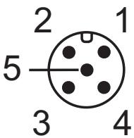 | 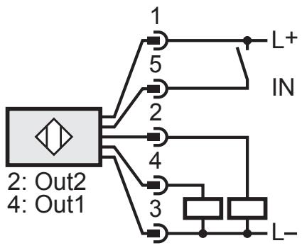 |
Core colours of ifm sockets:
1 = BN (brown), 2 = WH (white), 3 = BU (blue), 4 = BK (black) 5 = GR (grey).
6.1 Operation with IO-Link master
The unit is compatible with IO-Link master port class A (type A).

For operation with IO-Link master port class B (type B) observe the following:
As a standard, the unit is not compatible with master port class B (type B). Pin 2 (OU2) and pin 5 (IN1) are used for manufacturer-specific functions. That means that the main supply voltage of the unit and the additional voltage supply (master port class B on pins 2/5) are not electrically isolated.
With the following configurations the unit can be used with master port class B:
- Connect unit and IO-Link master via 3 wires: Connect pins 1, 3 and 4 of the unit with the IO-Link master (do not connect pins 2 and 5).
- Connect unit and IO-Link master via 4 wires: Deactivate pin 2 (OU2) via IO-Link (setting OU2 = "off") and connect pins 1, 2, 3 and 4 of the unit with the IO-Link master (do not connect pin 5).
7 Operating and display elements
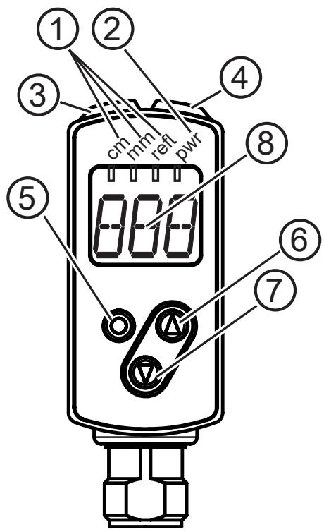
| 1: | 3 LEDs green | Active LED = set display unit (cm, mm, refl) |
| 2: | 1 LED green | Active LED = power |
| 3: | 1 LED orange | Switching status Out 1 |
| 4: | 1 LED orange | Switching status Out 2 |
| 5: | Programming button[ENTER] | Selection of the parameters and acknowledgement of the parameter values |
| 6: | Programming button"up" | Setting of the parameter values (scrolling by holding pressed, incremental by pressing briefly). |
| 7: | Programming button"down" | Setting of the parameter values (scrolling by holding pressed, incremental by pressing briefly). |
| 8: | 3-digit alphanumeric display | Indication of the measured distance or reflectivity, the parameters and parameter values. |
7.1 Meaning of the display colours
7.1.1 Use of the display colours in the menu
| Menu level | Green | Red |
| 0 | X | X |
| 1 | X | |
| 2 | X | |
| The colours indicate the logic state of the sensor. | ||

The green display colour indicates that there is an object in the monitored distance range, regardless of the setting of the switching outputs.
Example Fig. 1 (setting OUT1 = hno)
Display is green if:
• measured value ≤ SP1
Fig. 1
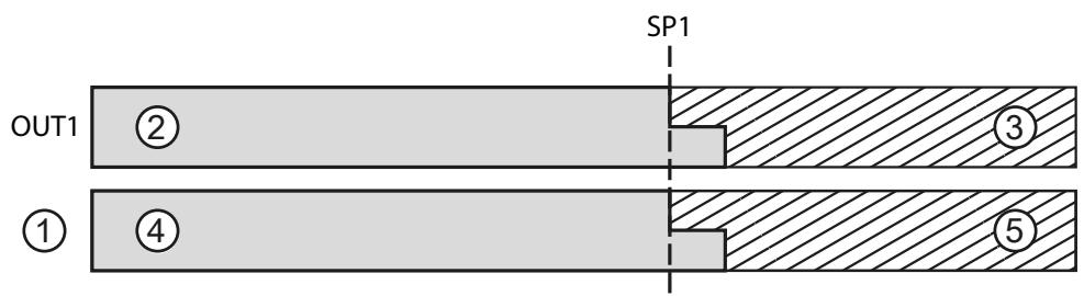
1: Display colour
2: High
3: Low
4: Green
5: Red
8 Menu
8.1 Menu structure for window function
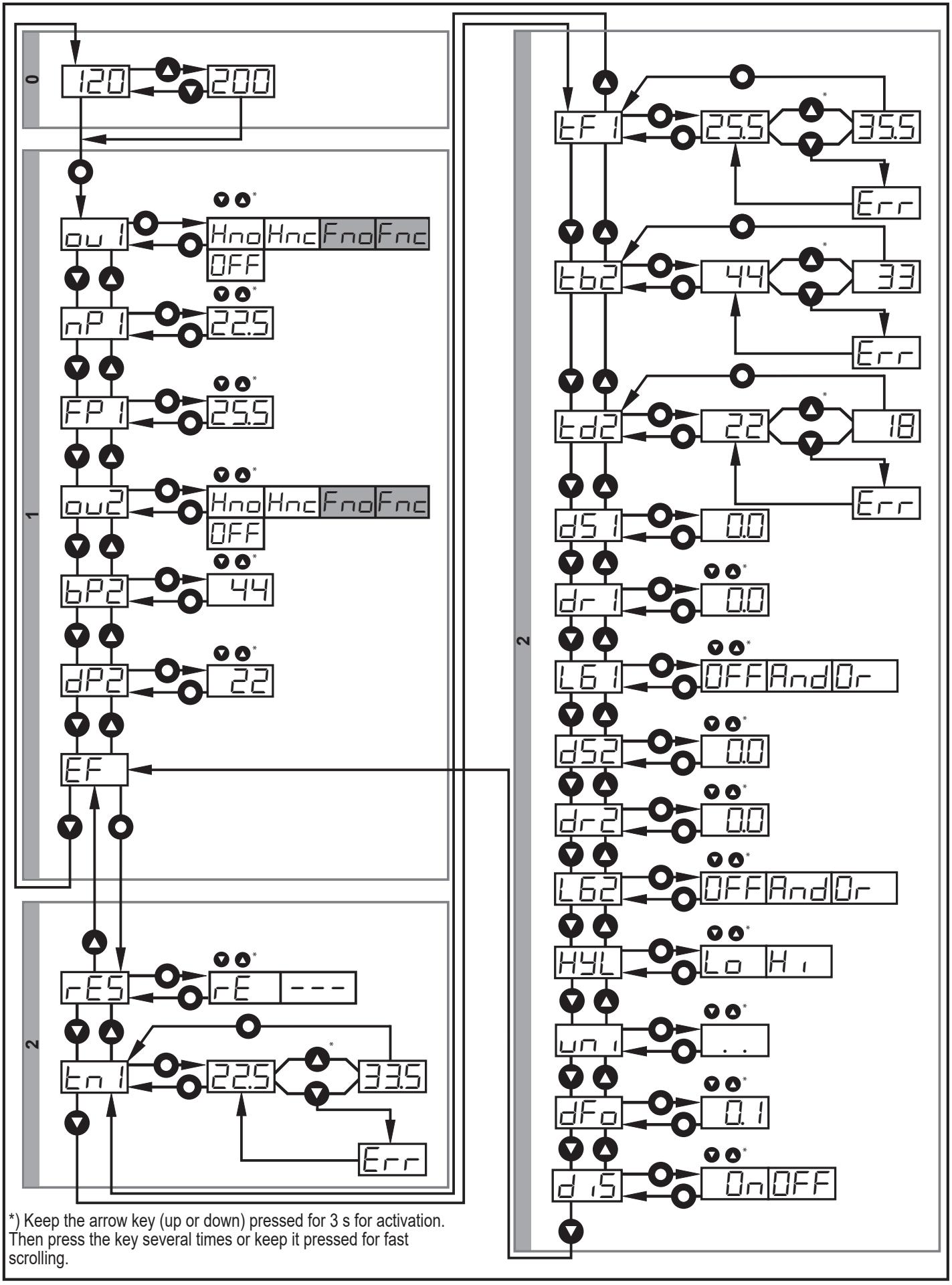
○ = [ENTER]
▲ = "Up" button
▼ = "Down" button
8.2 Menu structure for hysteresis function
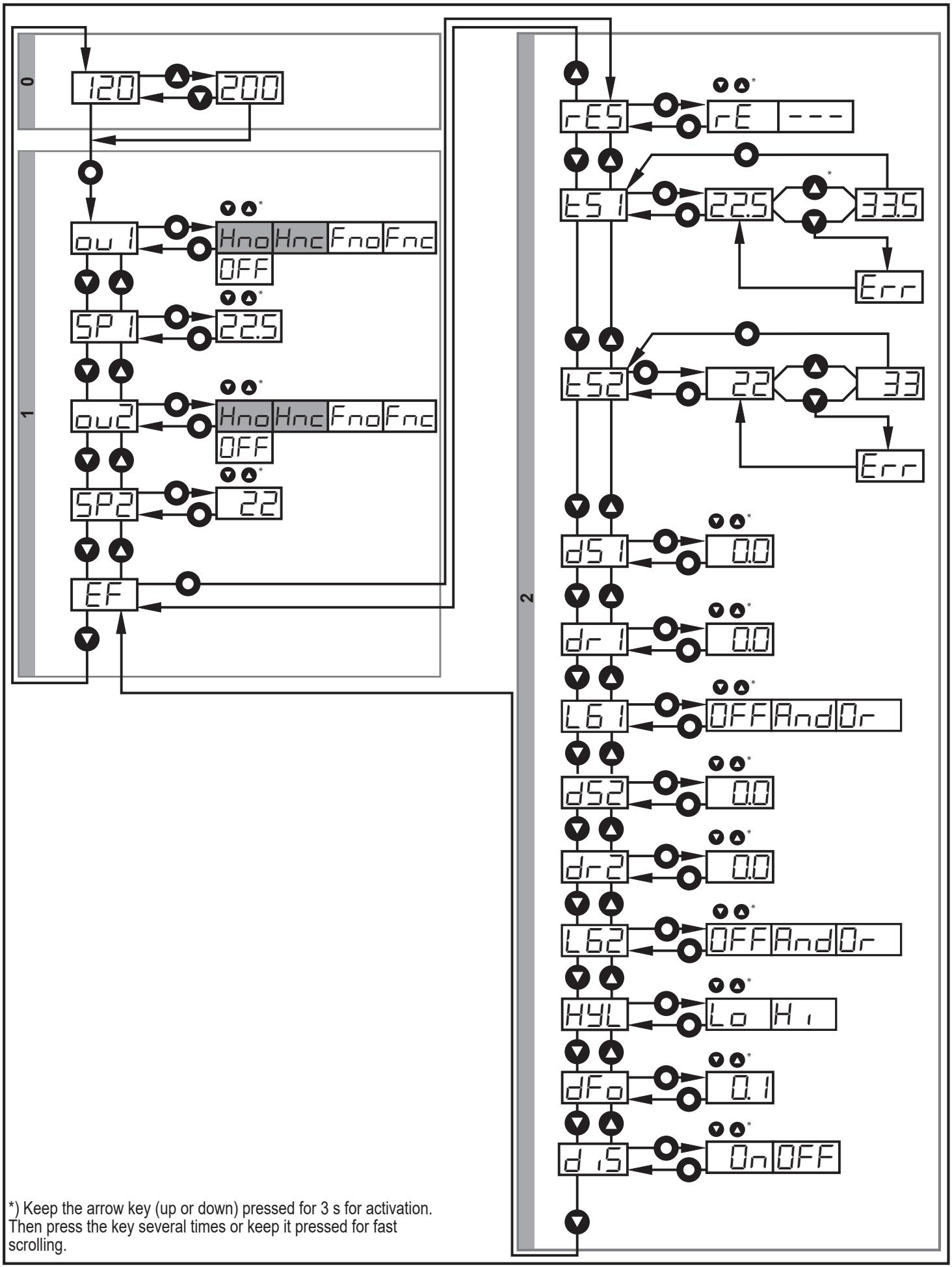
O = [ENTER]
▲ = "Up" button
▼ = "Down" button
8.3 Explanation of the menu
For the factory settings please refer to the end of these instructions ( → 15 Factory setting).
| OU1 | Configuration for output 15 switching functions can be selected:[Hno], [Hnc], [Fno], [Fnc], [OFF] → 10.2.1 Configure OUT1 / OUT2. |
| OU2 | Configuration for output 25 switching functions can be selected:[Hno], [Hnc], [Fno], [Fnc], [OFF] → 10.2.1 Configure OUT1 / OUT2. |
| SP1 | Switch point for hysteresis function OUT1 Limit at which the output with selected hysteresis function changes its switching status (object nearer/farther than distance set). [SP1] is only active if [OU1] = [Hno] or [Hnc]→ 10.2.5 Set the switch point for the hysteresis function OUT1 /OUT2. |
| SP2 | Switch point for hysteresis function OUT2 Value at which the output with selected hysteresis function changes its switching status (object brighter/darker than reflectivity set). [SP2] is only active if [OU2] = [Hno] or [Hnc]→ 10.2.5 Set the switch point for the hysteresis function OUT1 /OUT2. |
| nP1FP1 | Switch points for window function OUT1 Values at which the output with selected window function changes its switching status (object present / not present between the distance "near" and the distance "far"). [nP1] = switch point "near" / [FP1] = switch point "far". [nP1/FP1] are only active if [OU1] = [Fno] or [Fnc]→ 10.2.8 Set the switch points for window function OUT1 /OUT2.. |
| bP2dP2 | Switch points for window function OUT2 Limits at which the output with selected window function changes its switching status (object reflectivity between "bright" and "dark"). [bP2] = switch point "bright" / [dP2] = switch point "dark". [bP2] / [dP2] are only active if [OU2] = [Fno] or [Fnc]→ 10.2.8 Set the switch points for window function OUT1 /OUT2. |
| EF | Extended functions Press [ENTER] to open the submenu "Extended functions" |
| rES | Restore the factory setting→ 10.3.8 Reset all parameters to factory setting. |
| d51dr1d52dr2 | Delay for the switching outputs[dSx] = switch-on delay; [drx] = switch-off delay. The output does not immediately change its switching status when the switching condition is met but only after the delay has elapsed. If the switching condition is no longer met after the delay has elapsed, the switching status of the output does not change. [dSx] and [drx] are not effective if [OU1/2] = [OFF]→ 10.3.6 Set the delay time for switching outputs. |
| t51 | Background teach for hysteresis function OUT1 Teach function for [SP1]. [tS1] is only active if [OU1] = [Hno] or [Hnc]→ 10.3.2 Set background teach for hysteresis function OUT1 / OUT2. |
| t52 | Background teach for hysteresis function OUT2 Teach function for [SP2]. [tS2] is only active if [OU2] = [Hno] or [Hnc]→ 10.3.2 Set background teach for hysteresis function OUT1 / OUT2. |
| tn1tF1 | Teach switch points for window function OUT1 / 2 Limits at which the output with selected window function changes its switching status (object present / not present between the distance "near" and the distance "far"). [tn1] = switch point "near" / [tF1] = switch point "far". [tn1] / [tF1] are only active if [OU1] = [Fno] or [Fnc]. [tn2] = switch point "near" / [tF2] = switch point "far". [tn2] / [tF2] are only active if [OU2] = [Fno] or [Fnc](→ 10.3.3 Teach the switch point for window function OUT1 / OUT2) |
| t62td2 | Teach switch points for window function OUT2 Teach function for [bP2] / [dP2]. [tb2] = switch point [bP2] "bright" / [td2] = switch point [dP2] "dark". [tb2] / [td2] are only active if [OU2] = [Fno] or [Fnc].(→ 10.3.3 Teach the switch point for window function OUT1 / OUT2) |
| HYL | Set the switching hysteresis levels for OUT2 The switching hysteresis for the object reflectivity can be set in 2 steps: [lo],[hi] → 10.3.4 Set switching hysteresis level for OUT2 |
| L61L62 | Logic operator of the switching outputs Status of the switching output 1 / 2 is the result of the logic function of the following input parameters:- status of the switching output 1 if no logic function were selected- status of the switching output 2 if no logic function were selected→ 10.3.5 Set the logic function for switching outputs. |
| dFo | Set the fault suppression time for switching outputs This function suppresses brief saturation of the measuring element (such saturation may result from direct reflection or strong fluctuations in brightness). During the set delay time, the latest valid value measured is displayed, the output signals remain unchanged.(→10.3.7 Set the fault suppression time). |
| d15 | Set the display2 settings can be selected:[on], [OFF] With the setting [OFF], the display is switched off automatically after 30 sec. Only the "power-on" LED remains active. Each push of the button re-activates the display for 15 sec.(→10.3.1 Set the display) |
9 Operating modes
9.1 Run mode
The run mode is the normal operating mode.
After power on the unit is in the Run mode. It carries out its monitoring function and generates output signals according to the set parameters.
The display indicates the current distance or the object reflectivity, the yellow LEDs signal the switching status of the outputs.

The measuring distance is displayed in [cm].
• Value range 0...99.9 cm with one decimal place (mm resolution)
• Value range 100...165 cm without decimal place (cm resolution)
The object reflectivity is displayed in [%]:
• Value range = 0...999
- A value of 100% corresponds to the reflectivity of a white Kodak Gray Card if the sensor is aligned vertically to the object.
- A value of 20% corresponds to the reflectivity of a grey Kodak Gray Card if the sensor is aligned vertically to the object.
Reflective surfaces can generate values considerably larger than 100%.
Switch between the two measured values via the "up" or "down" button.
9.2 Display mode
Indication of the parameters and the set parameter values.
▶ Briefly press [ENTER].
▷ The unit goes to the display mode. Internally it remains in the operating mode. The set parameter values can be read:
▶ To scroll through the parameters, briefly press the "up"/"down" button.
▶ To display the parameter value, briefly press [Enter].
▷ After another 15 s the unit returns to the Run mode.
9.3 Programming mode
Set the parameter values → 10.1 General parameter setting.
10 Parameter setting
During parameter setting the unit remains internally in the operating mode. It continues its monitoring function with the existing parameters until the change has been completed.
10.1 General parameter setting
10.1.1 Set a parameter value
| 1 | Select parameter ▶ Press [ENTER] to access menu level 1. ▶ Press the "up"/"down" button until the requested parameter is displayed. | 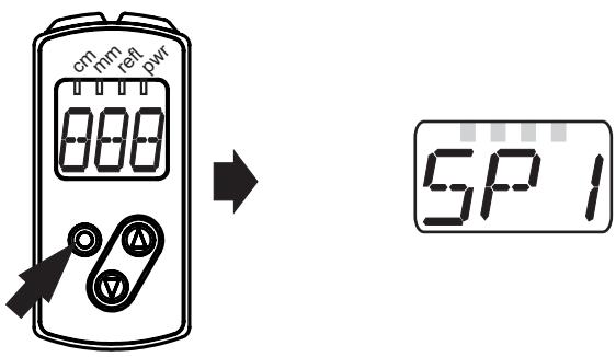 |
| 2 | Set parameter value▶ Briefly press [ENTER]. ▷ The current parameter value is displayed. ▶ Press the "up" or "down" button and keep it pressed.> The current parameter value flashes for 3 s. ▶ Increase the setting value step by step by pressing the button once or continuously by holding it down. | 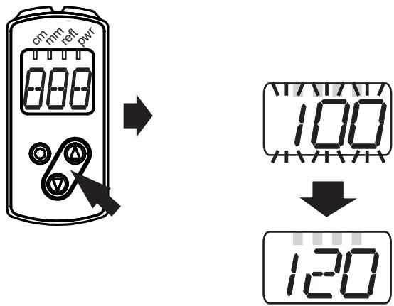 |
| Decrease the value: let the display move to the maximum setting value. Then the cycle starts again at the minimum setting value. | ||
| 3 | Confirmation of the parameter value▶ Briefly press [Enter].> Back to menu level 1▷ The parameter is displayed again; the new parameter value is effective. | |
| 4 | Set other parameters▶ Select a parameter as described in step 1 and continue with step 2. | |
| 5 | Finish parameter setting▶ Wait for 15 s or press the "up" and "down" button. ▶ If necessary, repeat several times to access menu level 0. ▷ The current measured value is displayed. | |
10.1.2 Change from menu level 1 to menu level 2
| ▶ Press the "down" button until [EF] is displayed. |  |
| ▶ Briefly press [Enter]. ▷ The first parameter of the submenu is displayed (here: [rES]). | 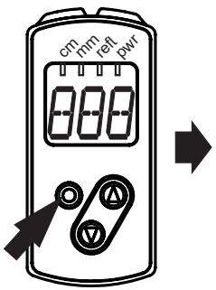 |  |
10.1.3 Electronic lock
The unit can be locked electronically to prevent unauthorised setting. On delivery the unit is not locked.
| Locking▶ Make sure that the unit is in the normal operating mode. ▶ Keep the "up" + "down" button pressed (approx. 10 s) until [Lo] is displayed. ▷ The unit is locked. |  | 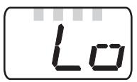 |
| [Lo] is displayed briefly if you try to change parameter values on the locked unit during operation. | ||
| Unlocking▶ Keep the "up" + "down" button pressed until [uLo] is displayed. ▷ The unit is unlocked. |  | 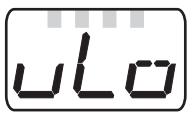 |
Timeout

If no button is pressed for 15 s during the setting procedure, the unit returns to the Run mode with unchanged values.
10.2 Configuration of the basic settings
10.2.1 Configure OUT1 / OUT2
| ▶ Select [OU1] / [OU2] and set the switching functions. Switching functions:• [Hno] = hysteresis function / normally open• [Hnc] = hysteresis function / normally closed• [Fno] = window function / normally open• [Fnc] = window function / normally closed• [OFF] = switching output is deactivated▶ Confirm with [ENTER]. |  |
10.2.2 Hysteresis function for OUT1
The hysteresis keeps the switching status of the output stable if the measured value varies about the sensing range. The selected switch point [SP1] is the set point. The reset point is automatically set above the selected switch point [SP1] by the sensor. The nominal distance between set point and reset point is the hysteresis, it is indicated in the data sheet. The hysteresis depends on the reflectivity of the background.
Example Hno
- For the output function [Hno] the output switches when the object approaches and when the set point (A) is reached.
- When the object is removed again, the output does not switch back before the reset point (B) is exceeded.
The reset point (B) is above the set point (A).
1

2

[SP1] = switch point; A = set point; B = reset point
If the output function [Hnc] has been selected, the set and reset points are reversed. The output switches off when the object approaches. When the object is removed again, the output switches on.
Switching status of the outputs
| Output function | Object distance (D) | Switching status |
| [Hno] | D < [SPx] | closed |
| D > [SPx] | open | |
| [Hnc] | D < [SPx] | open |
| D > [SPx] | closed |
10.2.3 Dynamic hysteresis
The measured values detected by the sensor vary depending on the situation. The highest fluctuation of measured values occurs in case of a small signal to noise ratio. This is the case when very dark targets are detected and when there is very much ambient light. Therefore, the reset point is automatically set by the sensor after [SP1] has been selected.
Very dark background = high hysteresis is selected.
Very bright background = small hysteresis is selected.
The minimum distance between object and background is reduced if the background is very bright (e.g. white).
A bright background enables the detection of smaller objects.
10.2.4 Hysteresis function for OUT2
The hysteresis keeps the switching status of the output stable if the measured value varies about the reflectivity value. The selected switch point [SP2] is the set point. The reset point is automatically set above the selected switch point [SP2] by the sensor. The nominal reflectivity difference between set and reset point is the hysteresis which is indicated in the data sheet.
Example Hno
- For the output function [Hno] the output switches when the object reflectivity increases and when the set point (A) is reached.
- When the object gets darker, the output does not switch back before the value is below the reset point (B).
The reset point (B) is smaller than the set point (A).
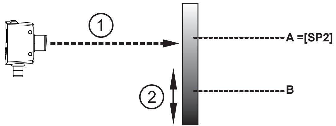
1: Laser beam
A: Set point "bright" [SP2]
2: Direction of movement object
B: Reset point
If the output function [Hnc] has been selected, the set and reset points are reversed. The output switches on if the object reflectivity is decreased. If the object reflectivity is increased, the output switches off.
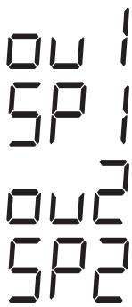
10.2.5 Set the switch point for the hysteresis function OUT1 /OUT2
▶ In [OU1] / [OU2], select the output function [Hno] or [Hnc].
▶ Confirm with [ENTER].
▶ Select [SP1] and set the switch point.
▶ Confirm with [ENTER].
10.2.6 Window function for OUT1
It is possible to define a window for the object recognition for output (OUT1).
Switches when the object is detected

[nP1] = switch point "near"; [FP1] = switch point "far"; FE = window
If the measured value is between the switch point "near" [nP1] and the switch point "far" [FP1], the output is switched on (when [OU1] = [Fno]).
Switches off when the object is detected

[nP1] = switch point "near"; [FP1] = switch point "far"; FE = window
If the measured value is between the switch point "near" [nP1] and the switch point "far" [FP1], the output is switched off (when [OU1] = [Fnc]).

The parameters [nP1] and [FP1] can also be set via the teach function.
The reset points are set dynamically by the sensor → 10.2.3 Dynamic hysteresis.

The minimum distance between [nP1] and [FP1] is 1 mm.
Condition: nP1 < FP1
e.g. teaching of nP1 > FP1 is not adopted by the sensor.
10.2.7 Window function for OUT2
It is possible to define an object reflectivity window for the object detection for output (OUT2).

1: Laser beam
2: Direction of movement object
3: Window
A: Switch point "bright" [bP2]
B: Switch point "dark" [dP2]
Switches when the object is detected
If the measured value is between switch point "bright" [bP2] and switch point "dark" [dP2], the output is switched on (when [OU2] = [Fno]).
Switches off when the object is detected
If the measured value is between switch point "bright" [bP2] and switch point "dark" [dP2], the output is switched off (when [OU2] = [Fnc]).

The parameters [bP2] and [dP2] can also be set via the teach function. The reset points are set dynamically by the sensor.

The minimum distance between [bP2] and [dP2] is 1 %.
Condition: dP2 < bP2
e.g. teaching of dP2 > bP2 is not adopted by the sensor.
Switching status of the outputs for OUT2
| Output function | Object reflectivity (R) | Switching status |
| [Fno] | R < [dP2] | open |
| R > [bP2] | ||
| [dP2] < R < [bP2] | closed | |
| [Fnc] | R < [dP2] | closed |
| R > [dP2] | ||
| [dP2] < R < [bP2] | open | |
| Both window limits ([bP2] and [dPx]) work with a switching hysteresis → 10.3.1 Set the display / Example of output function [Hno]. | ||
10.2.8 Set the switch points for window function OUT1 /OUT2.
| ▶ In [OU1], select the output function [Fno] or [Fnc]. ▶ Confirm with [ENTER]. ▶ Select [nP1] / [bP2] and set switch point "near" / "bright". ▶ Confirm with [ENTER]. ▶ Select [FP1] / [dP2] and set switch point "far" / "dark". ▶ Confirm with [ENTER]. | ou 1nP 1FP 1ou2bp2dP2 |
10.3 Extended functions
10.3.1 Set the display
| ▶ Change to [EF]. ▶ Select [diS] and make settings.2 settings can be selected:[On] = the measured value display is activated in the Run mode. [OFF] = measured value display is deactivated in the Run mode. When one button is pressed, the current measured value is displayed for 15 s. ▶ Confirm with [ENTER]. The LEDs remain active even if the display is deactivated. | d,5 |
10.3.2 Set background teach for hysteresis function OUT1 / OUT2
| ▶ In [OU1] / [OU2], select the output function [Hno] or [Hnc]. ▶ Confirm with [ENTER]. ▶ Change to [EF]. ▶ Select [tS1] / [tS2]. ▷ Parameter value for [SP1] / [SP2] is displayed. ▶ Press the "up" or "down" button and keep it pressed. ▷ The parameter value flashes for 3 s. ▷ New parameter value is displayed. ▶ Confirm with [ENTER]. ▷ The taught value is saved in [SP1] / [SP2]. | 0415104252 |

The sensor is aligned to the background.
The teach process sets [SP2] so that objects with a higher reflectivity (brighter objects) are reliably detected against the background (if [ou2] = [hno]).
Set point and reset point are set automatically
→ 10.2.3 Dynamic hysteresis.
10.3.3 Teach the switch point for window function OUT1 / OUT2
| ▶ In [OU1] / [OPU2], select the output function [Fno] or [Fnc]. ▶ Confirm with [ENTER]. ▶ Change to [EF]. ▶ Select [tn1] / [tb2]. ▷ Parameter value for [nP1] / [bP2] is displayed. ▶ Press the "up" or "down" button and keep it pressed. ▷ The parameter value flashes for 3 s. ▷ New parameter value is displayed. ▶ Confirm with [ENTER]. ▶ Select [tF1] / [td2]. ▷ Parameter value for [FP1] / [dP2] is displayed. ▶ Press the "up" or "down" button and keep it pressed. ▷ The parameter value flashes for 3 s. ▷ New parameter value is displayed. ▶ Confirm with [ENTER]. | ou ltn ltf lnp lFP lou2t62td2bp2dp2 |
10.3.4 Set switching hysteresis level for OUT2
| ▶ Change to [EF]. ▶ Select [HYL]. ▶ Select [Lo] or [Hi] with the arrow keys. ▶ Confirm with [ENTER]. | LoH1 |

Lo: Small hystereses enable detection of smaller reflectivity differences. This is the default setting.
Hi: Larger hystereses, to be used for difficult applications such as highly reflective surfaces.
For information about hysteresis curves → data sheet.
10.3.5 Set the logic function for switching outputs
| ▶ Change to [EF]. ▶ Select [LG1] / [LG2]. ▶ Select the logic function [OFF], [And] or [Or] with the arrow keys. ▶ Confirm with [ENTER]. | L61L62 |

Two input parameters are required for the logic operators AND / OR.
The logic function is bypassed if [OU2] or [OU1] is set to [OFF]. The setting parameters [LG1] / [LG2] are not changed.
The logic function is deactivated with [OFF].

If only output OUT1 is electrically wired, the object reflectivity can be evaluated on output OUT1 via logic function.
10.3.6 Set the delay time for switching outputs
| ▶ Change to [EF]. ▶ Select a parameter with the "up" or "down" button: [dS1] / [dS2] = switch-on delay; [dr1] / [dr2] = switch-off delay▶ Set the parameter value with [ENTER]: ▷ Set parameter value is displayed. ▶ Keep the "up" or "down" button pressed for at least 3 s. ▷ Parameter value flashes. ▶ Set the parameter value by means of the "up" or "down" button. Setting range [s]: 0...5 s in steps of 0.1 s (0 = delay time is not active)▶ Confirm with [ENTER]. | d51dr1d52dr2 |
10.3.7 Set the fault suppression time
| ▶ Change to [EF]. ▶ Select the parameter [dFo] with the "up" or "down" button:▶ Set the parameter value with [ENTER]:▷ Set parameter value is displayed. ▶ Keep the "up" or "down" button pressed for at least 3 s. ▶ Parameter value flashes. ▶ Set the parameter value by means of the "up" or "down" button. Setting range [s]: 0...5 s in steps of 0.1 s▶ Confirm with [ENTER]. ▷ The setting applies to OUT1 and OUT2 | dFO |
10.3.8 Reset all parameters to factory setting
| ▶ Change to [EF]. ▶ Select [rES] with the "up" or "down" button, then press [Enter]. ▷ [ rE] is displayed. ▶ Keep the "up" or "down" button pressed until [---] is displayed. ▶ Confirm with [ENTER]. ▷ All parameters are reset to factory setting. | r-ES |
11 IO-Link
11.1 General information
This unit has an IO-Link communication interface which requires an IO-Link-capable module (IO-Link master) for operation.
The IO-Link interface enables direct access to the sensor values and parameters and provides the possibility to set the parameters of the unit during operation. In addition, communication is possible via a point-to-point connection with a USB adapter cable.
You will find more detailed information about IO-Link at www.ifm.com.
11.2 Device-specific information
You will find the IODDs necessary for the configuration of the IO-Link unit and detailed information about sensor values, diagnostic information and parameters in the overview table at www.ifm.com.
11.3 Parameter setting tools
You will find all necessary information about the required IO-Link hardware and software at www.ifm.com.
11.4 Functions
With IO-Link all functions and measured data are available that can also be accessed via the display and pushbuttons on the unit.
The process data value includes the measuring distance and the object reflectivity.
All functions are described in detail in the IODD.
12 Set-up / Operation
▶ After installation, electrical connection and programming, check whether the unit operates correctly.
▷ If the unit has been correctly set up, the object distance or the object reflectivity is indicated. The settings made last are internally stored by the sensor.
12.1 Error indications
12.1.1 Error indications for OUT1
| Display | Possible cause | Switching output | |||
| [Hno] | [Hnc] | [Fno] | [Fnc] | ||
| [-|-] | too much light, e.g. reflective surface | ON | OFF | OFF | ON |
| [--] | not enough light, no object | OFF | ON | OFF | ON |
| [nEA] | object to be measured outside the measuring range < 80 mm | ON | OFF | OFF | ON |
| [FAr] | object to be measured outside the measuring range > 165 cm | OFF | ON | OFF | ON |
| [OFF] | laser is switched off | OFF | ON | OFF | ON |
| [ERP] | plausibility (e.g. object too fast) | X1) | X1) | X1) | X1) |
| [ute] | ambient temperature too low, laser is switched off | OFF | ON | OFF | ON |
| [SC1] | short circuit in switching output 1 | ||||
12.1.2 Error displays for OUT2
| Display | Possible cause | Switching output | |||
| [Hno] | [Hnc] | [Fno] | [Fnc] | ||
| [-|-] | too much light, e.g. reflective surface | ON | OFF | OFF | ON |
| [--] | not enough light, no object | OFF | ON | OFF | ON |
| [nEA] | object to be measured outside the measuring range < 80 mm | X1) | X1) | X1) | X1) |
| [FAr] | object to be measured outside the measuring range > 165 cm | X1) | X1) | X1) | X1) |
| [OFF] | Laser is switched off | OFF | ON | OFF | ON |
| [ERP] | plausibility (e.g. object too fast) | X1) | X1) | X1) | X1) |
| [ute] | ambient temperature too low, laser is switched off | OFF | ON | OFF | ON |
| [SC2] | short circuit in switching output 2 | ||||
1) unchanged
13 Maintenance, repair, disposal
Faulty sensors must only be repaired by the manufacturer.
▶ Keep the front lens of the sensor clean.
▶ After use dispose of the unit in an environmentally friendly way in accordance with the applicable national regulations.
▶ Do not open the module housing. There are no user-serviceable components inside.
14 Scale drawing
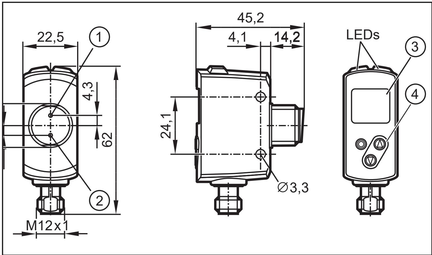
Dimensions in mm
1: 3-digit alphanumeric display / LED function displays
2: Programming buttons
15 Factory setting
| Parameters | Setting range | Factory setting | Own setting |
| OU1 | Hno, Hnc, Fno, Fnc, OFF | Hno | |
| SP1 [cm] | 8.5...150 | 150 | |
| nP1 [cm] | 8.5...150 | 20.0 | |
| FP1 [cm] | 8.5...150 | 25.0 | |
| dS1 [s] | 0...0, 1...5 | 0 | |
| dr1 [s] | 0...0, 1...5 | 0 | |
| LG1 | And, Or, OFF | OFF | |
| OU2 | Hno, Hnc, Fno, Fnc, OFF | Hno | |
| SP2 [%] | 6...900 | 10 | |
| bP2 [%] | 6...900 | 60 | |
| dP2 [%] | 6...900 | 30 | |
| dS2 [s] | 0...0, 1...5 | 0 s | |
| dr2 [s] | 0...0, 1...5 | 0 s | |
| HyL | Lo, Hi | Lo | |
| LG2 | And, Or, OFF | OFF | |
| dFo [s] | 0...0, 1...5 | 0.1 s | |
| diS | On / OFF | On |
Technical data and further information at www.ifm.com

- 1 PRELIMINARY NOTE
- 1.1 SYMBOLS USED
- 1.2 WARNINGS USED
- 2 SAFETY INSTRUCTIONS
- 3 FUNCTIONS AND FEATURES
- 3.1 GENERAL NOTES
- 3.2 APPLICATIONS
- 3.3 INSTALLATION INSTRUCTIONS
- 3.3.1 AVOIDANCE OF SOILING AND AMBIENT LIGHT
- 3.3.2 AVOIDANCE OF MUTUAL INTERFERENCE
- 3.3.3 SENSOR ALIGNMENT TO MOVING OBJECTS
- 4 FUNCTIONS
- 4.1 OUTPUT FUNCTION HYSTERESIS
- 4.2 OUTPUT FUNCTION WINDOW
- 4.3 SWITCH OFF THE LASER
- 4.4 LOGIC OPERATOR OF THE SWITCHING OUTPUTS
- 5 INSTALLATION
- 5.1 INSTALLATION CONDITIONS
- 5.2 MOUNTING ACCESSORIES
- 6 ELECTRICAL CONNECTION
- 6.1 OPERATION WITH IO-LINK MASTER
- 7 OPERATING AND DISPLAY ELEMENTS
- 7.1 MEANING OF THE DISPLAY COLOURS
- 7.1.1 USE OF THE DISPLAY COLOURS IN THE MENU
- 8 MENU
- 8.1 MENU STRUCTURE FOR WINDOW FUNCTION
- 8.2 MENU STRUCTURE FOR HYSTERESIS FUNCTION
- 8.3 EXPLANATION OF THE MENU
- 9 OPERATING MODES
- 9.1 RUN MODE
- 9.2 DISPLAY MODE
- 9.3 PROGRAMMING MODE
- 10 PARAMETER SETTING
- 10.1 GENERAL PARAMETER SETTING
- 10.1.1 SET A PARAMETER VALUE
- 10.1.2 CHANGE FROM MENU LEVEL 1 TO MENU LEVEL 2
- 10.1.3 ELECTRONIC LOCK
- 10.2 CONFIGURATION OF THE BASIC SETTINGS
- 10.2.1 CONFIGURE OUT1 / OUT2
- 10.2.2 HYSTERESIS FUNCTION FOR OUT1
- 10.2.3 DYNAMIC HYSTERESIS
- 10.2.4 HYSTERESIS FUNCTION FOR OUT2
- 10.2.5 SET THE SWITCH POINT FOR THE HYSTERESIS FUNCTION OUT1 /OUT2
- 10.2.6 WINDOW FUNCTION FOR OUT1
- 10.2.7 WINDOW FUNCTION FOR OUT2
- 10.2.8 SET THE SWITCH POINTS FOR WINDOW FUNCTION OUT1 /OUT2
- 10.3 EXTENDED FUNCTIONS
- 10.3.1 SET THE DISPLAY
- 10.3.2 SET BACKGROUND TEACH FOR HYSTERESIS FUNCTION OUT1 / OUT2
- 10.3.3 TEACH THE SWITCH POINT FOR WINDOW FUNCTION OUT1 / OUT2
- 10.3.4 SET SWITCHING HYSTERESIS LEVEL FOR OUT2
- 10.3.5 SET THE LOGIC FUNCTION FOR SWITCHING OUTPUTS
- 10.3.6 SET THE DELAY TIME FOR SWITCHING OUTPUTS
- 10.3.7 SET THE FAULT SUPPRESSION TIME
- 10.3.8 RESET ALL PARAMETERS TO FACTORY SETTING
- 11 IO-LINK
- 11.1 GENERAL INFORMATION
- 11.2 DEVICE-SPECIFIC INFORMATION
- 11.3 PARAMETER SETTING TOOLS
- 11.4 FUNCTIONS
- 12 SET-UP / OPERATION
- 12.1 ERROR INDICATIONS
- 12.1.1 ERROR INDICATIONS FOR OUT1
- 12.1.2 ERROR DISPLAYS FOR OUT2
- 13 MAINTENANCE, REPAIR, DISPOSAL
- 14 SCALE DRAWING
- 15 FACTORY SETTING
Brand : IFM
Model : OGD583
Category : Rangefinder