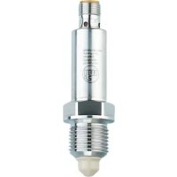
LMC100 - Sensor IFM - Free user manual and instructions
Find the device manual for free LMC100 IFM in PDF.


User questions about LMC100 IFM
0 question about this device. Answer the ones you know or ask your own.
Ask a new question about this device
Download the instructions for your Sensor in PDF format for free! Find your manual LMC100 - IFM and take your electronic device back in hand. On this page are published all the documents necessary for the use of your device. LMC100 by IFM.
USER MANUAL LMC100 IFM
Operating instructions
Binary level sensor
LMCxx0
Contents
1 Preliminary note.... 3
1.1 Symbols used.... 3
1.2 Warnings.... 3
2 Safety instructions 4
2.1 Cybersecurity 4
3 Transport, handling and storage 5
4 Intended use 6
4.1 Application area 6
4.2 Restriction of the application area.... 7
5 Function 8
5.1 Measuring principle 8
5.2 Process measured signals.... 8
5.3 Application examples 8
5.3.1 Application examples for front mounting 8
5.3.2 Application examples for rear mounting using a probe.... 9
6 Installation.... 10
6.1 Installation location / environment.... 10
6.2 Installation procedure.... 11
6.2.1 Front mounting for LMC1x0 / LMC5x0 / LMC8xx.... 11
6.2.2 Rear installation for LMC4x 11
7 Electrical connection 13
8 Parameter setting 14
8.1 Parameter setting via memory plug 14
8.2 Parameter 15
8.3 System commands.... 15
8.4 Perform full adjustment [Teach SPx].... 15
9 Operation.... 17
9.1 Switching states and LED indicators.... 17
10 Maintenance, repair and disposal 18
10 Maintenance, repair and disposal 18
11 Factory setting.... 19
10 Maintenance, repair and disposal.... 18 11 Factory setting.... 19
1 Preliminary note
You will find instructions, technical data, approvals and further information using the QR code on the unit / packaging or at documentation.ifm.com.
1.1 Symbols used
Requirement
Instruction
Reaction, result
bold Designation of keys, buttons or indications
→ Cross-reference without link
→ Cross-reference with link


1.2 Warnings
Warnings indicate the possibility of personal injury and damage to property. This enables safe product handling. Warnings are graded as follows:

WARNING
Warning of serious personal injury
▷ If the warning is not observed, fatal and serious injuries are possible.

CAUTION
Warning of minor to moderate personal injury
▷ If the warning is not observed, minor to moderate injuries are possible.

ATTENTION
Warning of damage to property
▷ If the warning is not observed, damage to property is possible.
2 Safety instructions
- The unit described is a subcomponent for integration into a system.
- The system architect is responsible for the safety of the system.
- The system architect undertakes to perform a risk assessment and to create documentation in accordance with legal and normative requirements to be provided to the operator and user of the system. This documentation must contain all necessary information and safety instructions for the operator, the user and, if applicable, for any service personnel authorised by the architect of the system.
- Read this document before setting up the product and keep it during the entire service life.
- The product must be suitable for the corresponding applications and environmental conditions without any restrictions.
- Only use the product for its intended purpose (→ Intended use).
- If the operating instructions or the technical data are not adhered to, personal injury and/or damage to property may occur.
- The manufacturer assumes no liability or warranty for any consequences caused by tampering with the product or incorrect use by the operator.
- Installation, electrical connection, set-up, operation and maintenance of the product must be carried out by qualified personnel authorised by the machine operator.
- Protect units and cables against damage.
- Only use the product for permissible media (→ Technical data).

CAUTION
With high medium temperatures, parts of the device may heat up.
▷ Risk of burns
▶ Do not touch the device.
▶ Protect the housing against contact with flammable substances and unintentional contact.
2.1 Cybersecurity
Installation
The device is suitable for operation in a secure environment according to IEC 62443-1-1.
The device was designed for operation behind a firewall.
▶ Carry out a risk assessment of the system according to IEC 62443-1-1.
▶ Take measures to ensure physical security.
Operation
▶ Observe the security functions described in the product documentation and the recommendations for their use.
Maintenance
- ▶ Back up system configuration and system data in accordance with your company’s change management processes.
Decommissioning
▶ Ensure that no sensitive information can fall into unauthorised hands.
▶ Always reset the system settings to the factory settings before decommissioning the device.
3 Transport, handling and storage

The probe tip must not be exposed to intense sunlight (UV radiation).
▶ Store the device in its original packaging.
▶ When the device is to be stored again, use the original packaging.
▶ Otherwise, provide unused connections with either a mating connector or a protective cap and pack the device in suitable packaging.
▶ Observe the permissible ambient conditions for the device during storage (→ Technical data).
▶ In case of return shipment, ensure that the unit is free from soiling, especially from dangerous and toxic substances.
4 Intended use
The unit monitors the level of liquid, viscous and powdery media in tanks and pipes. It can be used for point level detection and run-dry protection. The separate setting of two switching thresholds also enables the detection of two different media (can be used, for example, for phase separation or differentiation of media).
4.1 Application area
• Detection of almost all media, even extremely adhering or non-conductive ones.
- The sensitivity is preset at the factory. Simple set-up possible without any programming (plug and play).
- The sensitivity can be set by the user, if required: Parameter setting ➕ 14
- Available process connections: G 1/2 and 1/2" NPT and M12. G 1/2 is available in two versions: For front mounting and rear mounting.
| Type | Preset | Sensitivity | Process connection |
| LMC100 | Aqueous media | Low | G 1/2, front |
| LMC110 | Oils, greases, powders | High | |
| LMC140 | Aqueous media | Low | |
| LMC400 | Aqueous media | Low | G 1/2, rear |
| LMC410 | Oils, greases, powders | High | |
| LMC500 | Aqueous media | Low | 1/2" NPT |
| LMC510 | Oils, greases, powders | High | |
| LMC840 | Aqueous media | Low | M12 front |
Available process connections:
①

②

③

④

1: G 1/2, front
2: G 1/2, rear
3: 1/2" NPT
4: M12 front

With a suitable device the presence of certain media can be detected while build-up or foam is suppressed.
In addition, the device can be used for temperature measurement: Parameter setting ➞ 14
4.2 Restriction of the application area

The probe tip must not be exposed to intense sunlight (UV radiation).
• Not suitable for hygienic areas.
- Not suitable for abrasive media, for example quartz sand, or heavy bulk material.
• For use in aggressive media, acids and alkali:
▶ Check the compatibility of the product materials beforehand ➕ Technical data sheet.
- When used in media that are inhomogeneous, separate and thus form separation layers, for example, oil on water:
▶ Check the function by an application test.
• Air or gas bubbles in liquid media may lead to undesirable switching behaviour.
▶ Check the function by an application test. If required, adapt the sensitivity or set switching delays: Parameter setting ➞ 14
5 Function
5.1 Measuring principle

The unit operates on the impedance spectroscopy method. It analyses the electrical behaviour of the media to be monitored in the frequency range between 50 and 200 MHz. The probe tip generates an electrical field that is influenced by the level. The nature of the medium as well as build-up or foam have different electrical properties that are used for the evaluation.
Fig. 1: Measuring principle
5.2 Process measured signals
Factory setting:
The two outputs complement each other: MP1 / OUT1 = Hno; OUT2 = Hnc
| No media detected | MP1 / OUT1 = OFF | OUT2 = ON |
| Medium detected | MP1 / OUT1 = ON | OUT2 = OFF |
5.3 Application examples
5.3.1 Application examples for front mounting

Fig. 2: Installation on a tank

Fig. 3: Installation on a pipe
1: Installation position only suited to some extent
- Illustration of installation in a tank: Possible installation positions in a tank, for example, for level detection or as run-dry protection.
• Illustration of pipe installation: Fill level monitoring in pipes.

With highly adhesive and viscous media and media prone to sedimentation or build-up the installation positions (1) are only suitable to some extent. Residues might be detected as level.
5.3.2 Application examples for rear mounting using a probe
Installation from the top:
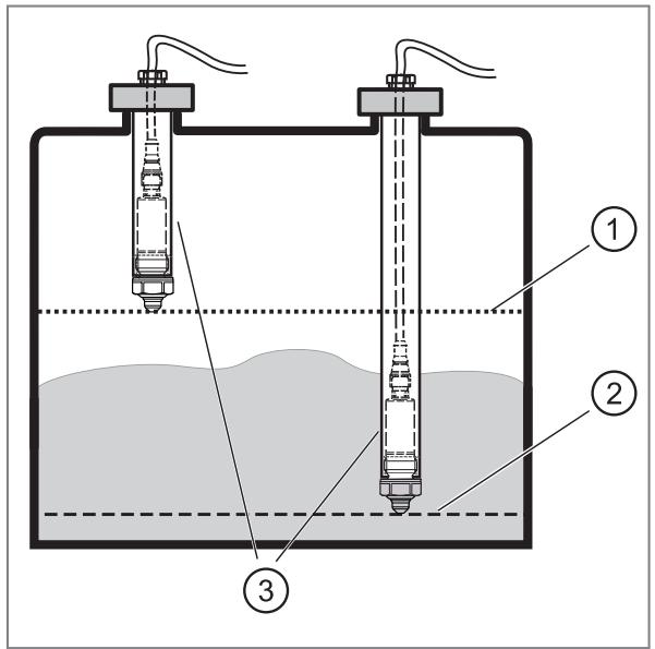
1: Maximum level
2: Minimum level
3: Probe
Rear installation of the sensor in a pipe of variable length (3) is possible. Different response points can be implemented.\ Example: monitoring maximum level (1) or minimum level (2).

Use a metal probe with a G 1/2 internal thread and an internal diameter of at least 19 mm.

If the sensor is permanently covered by the medium:
▶ The temperature in the pipe must not exceed the maximum ambient temperature as a result of an excessively high medium temperature ➞ Technical data sheet.
Lateral installation:

Since the probe tip is installed further into the tank, very adhesive and viscous residues can be suppressed.
6 Installation

CAUTION
Escaping compressed air or hot media.
▷ Risk of injury caused by pressure or burns.
▶ Before installing or removing the device, ensure that no pressure is applied to the system and that there is no medium in the pipe or tank.
▶ Note dangers related to machine / medium temperatures.

CAUTION
If the medium temperature is above 50\ °C ( 122\ °F ) parts of the housing can increase in temperature to over 65\ °C ( 149\ °F ).
▷ Risk of burns
▶ Do not touch the unit.
▶ Protect the housing against contact with flammable substances and unintentional contact.
▶ Allow the unit and process adapter to cool down before maintenance.

The sensor is supplied without installation / connection accessories.

Only use accessories from ifm electronic gmbh! The optimum function is not ensured when using components from other manufacturers.

Available accessories: www.ifm.com.
6.1 Installation location / environment
• Installation preferably in closed metal tanks or metal pipes.
- The sensor must be in electrical contact with the metal process connection.

In applications subjected to pressure:
▶ Only use process connections suitable for the process or the application.

When installed in plastic tanks, there may be deterioration caused by electromagnetic interference.
▶ Check the function by an application test.
▶ If interference occurs, take suitable measures such as shielding or earthing.

Fig. 4: Sensor tip distances
For installation in confined spaces, for example, in pipes, tank corners, structures in the tank or on agitators and other moving objects:
▶ To avoid malfunctions and damage to the sensor and plant, maintain a distance of at least 15 mm from the sensor tip to neighbouring objects, e.g. pipe and container walls, structures in the tank and other sensors.
6.2 Installation procedure
6.2.1 Front mounting for LMC1x0 / LMC5x0 / LMC8xx
▶ LMC1x0: ▶ Slide the supplied flat seal over the thread onto the sensor and/or verify its correct position.
▶ LMC5x0: If necessary, apply a suitable sealing material (e.g. PTFE tape) to the thread. Ensure that the sensor is in electrical contact with the metal process connection.
▶ LMC8xx: Slide the supplied O-ring over the thread onto the sensor and / or check its fit.
▶ Lightly grease the thread of the sensor using a lubricating paste which is suitable and approved for the application.
▶ Screw the sensor into the respective process connection and tighten it.
▶ Max. tightening torque: LMC1x0 = 20...25 Nm, LMC5x0 = < 50 Nm, LMC8xx = 20...25 Nm.
▶ After installation check the tank / pipe for ingress resistance.
6.2.2 Rear installation for LMC4x
▶ Guide the cable socket (straight version) through the probe provided (Figure 1).
▶ Slide the supplied flat seal over the (rear) thread onto the sensor and check that it fits properly (Figure 2).
▶ Screw the sensor to the cable socket (Figure 3).
▶ Lightly grease the thread of the sensor using a lubricating paste which is suitable and approved for the application.
▶ Screw the sensor to the probe and tighten (Figure 4). Max. tightening torque: 20...25 Nm).
▶ Fit the probe to the tank.
▶ Check the tank and pipe for ingress resistance after installation.
▶ Seal the cable entry at the upper end of the pipe in an appropriate manner (for example, by using a cable gland).


These instructions also apply for the installation in a tuning fork adapter. The cable entry of the adapter has to be sealed with the enclosed cover cap. The cable must be guided downwards so that moisture is discharged.
7 Electrical connection

The unit must be connected by a qualified electrician.
Observe the national and international regulations for the installation of electrical equipment.
Voltage supply according to SELV, PELV.
▶ Disconnect power.
▶ Connect the unit as follows:
Wiring LMC140 and LMC840

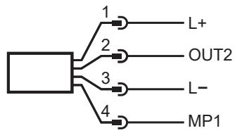
| Pin | Assignment |
| 1 | L+ |
| 2 | OUT2: DO2 |
| 3 | L- |
| 4 | MP1: DO1, IO-Link |
DO: digital output; MP: multi-function connection
LMCxxx wiring:

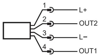
| Pin | Assignment |
| 1 | L+ |
| 2 | OUT2: Switching output |
| 3 | L- |
| 4 | OUT1: switching output / IO-Link |
Parameter setting (all versions):
| Pin | Assignment |
| 1 | L+ |
| 3 | L- |
| 4 | MP1 / OUT1: IO-Link |

Factory setting MP1 / OU1 and OUT2: Factory setting ➞ 19
8 Parameter setting
The device parameters can be set via the IO-Link interface in the following ways, for example:
- Parameter setting via a suitable parameter setting software, e.g. ifm moneo|configure
• Parameter setting via a PLC
• Parameter setting via an IIoT application
Requirements for parameter setting via the IO-Link interface:
√ The Input Output Device Description (IODD) for the device in case of parameter setting via a parameter setting software, see documentation.ifm.com
√ The IO-Link interface description (PDF) for the device in case of parameter setting via a PLC or IIoT application, see documentation.ifm.com
√ An IO-Link master
▶ Connect the IO-Link master to the parameter setting software, the PLC or the IIoT application.
▶ Connect the device to a suitable free port of the IO-Link master.
▶ Set the port of the IO-Link master to the IO-Link operating mode.
▷ The device changes to the IO-Link mode.
▶ Change the parameter settings in the software.
▶ Write the parameter settings to the device.

Support for system integration and parameter setting via IO-Link:
→ Manual of the parameter setting software (e.g. moneo)
Explanations and startup packages at ifm.com/cnt/io-link-system-integration.
Parameters can be set before installation or during operation.

If you change parameters during operation, this will influence the function of the plant.
▶ Ensure that there will be no malfunctions in your plant.
During parameter setting the unit remains in the operating mode. It continues to monitor with the existing parameter until the parameter setting has been completed.

With a suitable unit the presence of certain media can be detected while build-up or foam is suppressed. In many cases the factory setting is sufficient. For specific requirements, the sensitivity and additional functions can be adapted to the respective application. Splashes, undulations and air bubbles can be suppressed by setting a switching delay.
In addition, the unit can be used for temperature measurement. Temperature can only be measured via the IO-Link communication interface with acyclic data exchange. The probe tip must be sufficiently covered with the medium during the measurement.
8.1 Parameter setting via memory plug
Via a memory plug (→ Accessories), a parameter set can be written to the device. The memory plug can also be used to save the current parameter setting of a unit and to transfer it to other units of the same type.
▶ Load the appropriate parameter set into the memory plug ➕ Operating instructions Memory plug.
▶ Ensure that the device is in the delivery state.
▶ Connect the memory plug between device and socket.
▷ When voltage is supplied, the parameter set is transferred from the memory plug to the device.
▶ Remove the memory plug and put the unit into operation.
8.2 Parameter
| SPx/rPx | Switching thresholds of the switching points SPx and reset points rPx for the outputs MP1 / OUT1 and OUT2. The values for SPx / rPx are set in per cent of the maximum process value. The process value is defined as follows:Process value in air = 0 %Process value in tap water = 100 %Minimum hysteresis: 2 % | |
| Type of medium: | Reference values: | |
| Aqueous / water-based media: | SPx = 70 %, rPx = 62 % (factory setting LMCx0x) | |
| Media with low water content: | SPx = 35 %, rPx = 29 % | |
| Oils, fats, powders: | SPx = 8 %, rPx = 5 % (factory setting LMCx1x) | |
| oux | Output function for MP1 / OUT1 and OUT2:Hno= hysteresis function / normally open Hnc= hysteresis function / normally closed Fno= window function / normally open Fnc= window function / normally closed | |
| FOUx | Behaviour of the outputs MP1 / OUT1 in case of a fault. OFF= switching output switches OFF in case of a fault. On= switching output switches ON in case of a fault. | |
| dSx | Switching delay for MP1 / OUT1 and OUT2. Setting range 0...10 s. Step increment 0.1 s. | |
| drx | Switch-off delay for MP1 / OUT1 and OUT2. Setting range 0...10 s. Step increment 0.1 s. | |
| P-n | Switching logic for the outputs (PnP or nPn) | |
x = 1 configured MP1 / OUT1, x = 2 configured OUT2
8.3 System commands
| Teach SP1 | Teach to medium 1 Full adjustment to medium 1 to be detected, automatically sets the switching thresholds SP1/rP1 for MP1 / OUT1. No teach is possible for oux = Fno / Fnc. |
| Teach SP2 | Teach to medium 2 Full adjustment to medium 2 to be detected, automatically sets the switching thresholds SP2/rP2 for OUT2. No teach is possible for oux = Fno / Fnc. |
| Reset to factory set- tings. | Factory reset |
8.4 Perform full adjustment [Teach SPx]
▶ Fill the tank or pipe.
▷ The probe tip must be completely covered with the medium.
▶ Execute the system command (click on the corresponding button).
▷ The device automatically sets the switching thresholds SPx / rPx.
▶ Check the function by an application test.
9 Operation
After power-on the device is in the operating mode. It carries out its measurement and evaluation functions and generates output signals according to the set parameters.
▶ Check whether the unit operates correctly.
9.1 Switching states and LED indicators

The table shows the factory settings.
In this state MP1 / OUT1 is = Hno and OUT2 = Hnc.
| Operating status | LEDs | MP1 / OUT1 | OUT2 |
| Device ready for operation, no medium detected | Green | Off | On |
| Device ready for operation, medium detected | Yellow | On | Off |
| No operating voltage | Off | Off | Off |
| Short circuit output 1 | Flashing yellow | - | 1) |
| Short circuit output 2 | Flashing yellow | 1) | - |
| Error / failure | - | Off | Off |
| 1) According to the level | |||

The LEDs always indicate the switching status of output MP1 / OUT1.
10 Maintenance, repair and disposal

When the medium is changed, it may also be necessary to use another type of unit or adapt the sensitivity.
▶ Check the sensor tip at regular intervals for deposits and damage. Clean the unit if badly soiled. Replace the device if damaged.
▶ After use, dispose of the unit in an environmentally friendly way in accordance with the applicable national regulations.
It is not possible to repair the device.
11 Factory setting
| LMCx0x | LMC140 | LMCx1x | LMC840 | User settings | |
| SP1 | 70 % | 70 % | 8 % | 70 % | |
| rP1 | 62 % | 62 % | 5 % | 62 % | |
| ou1 | Hno | Hno | Hno | Hno | |
| SP2 | 70 % | 70 % | 8 % | 70 % | |
| rP2 | 62 % | 62 % | 5 % | 62 % | |
| ou2 | Hnc | Hnc | Hnc | Hnc | |
| FOU1 | OFF | OFF | OFF | OFF | |
| FOU2 | OFF | OFF | OFF | OFF | |
| dS1 | 0.0 | 0.0 | 0.0 | 0.0 | |
| dS2 | 0.0 | 0.0 | 0.0 | 0.0 | |
| dr1 | 0.0 | 0.0 | 0.0 | 0.0 | |
| dr2 | 0.0 | 0.0 | 0.0 | 0.0 | |
| P-n | PnP | nPn | PnP | nPn |
- 1 PRELIMINARY NOTE
- 1.1 SYMBOLS USED
- 1.2 WARNINGS
- 2 SAFETY INSTRUCTIONS
- 2.1 CYBERSECURITY
- 3 TRANSPORT, HANDLING AND STORAGE
- 4 INTENDED USE
- 4.1 APPLICATION AREA
- 4.2 RESTRICTION OF THE APPLICATION AREA
- 5 FUNCTION
- 5.1 MEASURING PRINCIPLE
- 5.2 PROCESS MEASURED SIGNALS
- 5.3 APPLICATION EXAMPLES
- 5.3.1 APPLICATION EXAMPLES FOR FRONT MOUNTING
- 5.3.2 APPLICATION EXAMPLES FOR REAR MOUNTING USING A PROBE
- 6 INSTALLATION
- 6.1 INSTALLATION LOCATION / ENVIRONMENT
- 6.2 INSTALLATION PROCEDURE
- 6.2.1 FRONT MOUNTING FOR LMC1X0 / LMC5X0 / LMC8XX
- 6.2.2 REAR INSTALLATION FOR LMC4X
- 7 ELECTRICAL CONNECTION
- 8 PARAMETER SETTING
- 8.1 PARAMETER SETTING VIA MEMORY PLUG
- 8.2 PARAMETER
- 8.3 SYSTEM COMMANDS
- 8.4 PERFORM FULL ADJUSTMENT [TEACH SPX]
- 9 OPERATION
- 9.1 SWITCHING STATES AND LED INDICATORS
- 10 MAINTENANCE, REPAIR AND DISPOSAL
- 11 FACTORY SETTING
Brand : IFM
Model : LMC100
Category : Sensor