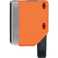
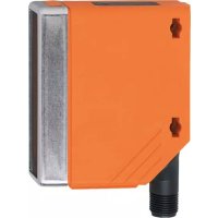
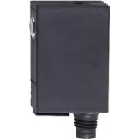
O5S700 - Photoelectric barrier IFM - Free user manual and instructions
Find the device manual for free O5S700 IFM in PDF.


User questions about O5S700 IFM
0 question about this device. Answer the ones you know or ask your own.
Ask a new question about this device
Download the instructions for your Photoelectric barrier in PDF format for free! Find your manual O5S700 - IFM and take your electronic device back in hand. On this page are published all the documents necessary for the use of your device. O5S700 by IFM.
USER MANUAL O5S700 IFM
CE
Operating instructions Through-beam sensor
UK
O5E7xx
O5S7xx

1 Preliminary note
1.1 Symbols used
▶ Instruction
▷ Reaction, result
[...] Designation of pushbuttons, buttons or indications
→ Cross-reference

Important note
Non-compliance can result in malfunctions or interference.
2 Safety instructions
According to the cULus approval
Caution - Use of controls or adjustments or procedures other than those specified herein may result in hazardous radiation exposure.

Visible laser light; CLASS 1 LASER PRODUCT.
EN/IEC 60825-1 : 2007 and EN/IEC 60825-1 : 2014
Complies with 21 CFR 1040.10 except for conformance with IEC 60825-1
Ed. 3., as described in Laser Notice No. 56, dated May 8, 2019.
Position of the product label

Additional label

3 Functions and features
The through-beam sensor detects objects and materials without contact and indicates their presence by a switching signal.
Range 60 m.
4 Installation

▶ Install the receiver (O5E...) and secure it to a bracket.
▶ Align the transmitter (O5S...) to the receiver and fix it.
Maximum range is only possible with precise alignment.
5 Operating and display elements

1: LED
2: [OUT on]
3: [OUT off]
6 Electrical connection

The unit must be connected by a qualified electrician.
▶ The national and international regulations for the installation of electrical equipment must be adhered to.
▶ Voltage supply according to EN 50178.
▶ Disconnect power.
▶ Connect the unit as follows:
Receiver DC PNP

pin 1 = L + (10...36 V DC)
(pin 2 = not connected)
pin 3 = L-
pin 4 = load (PNP, 200 mA)
Transmitter DC

pin 1 = L + (10...36 V DC)
(pin 2 = not connected)
pin 3 = L-
(pin 4 = not connected)
7 Settings
7.1 The sensor is to switch when the object is detected
| 1 | ▶ Position the object   receiver transmitter receiver transmitter |
| ▶ Press [OUT on] for 2 s. ▷ The sensitivity is set to the object. ▷ The yellow LED flashes. | |
| 2 | ▶ Remove the object   receiver transmitter receiver transmitter |
| ▶ Press [OUT off]. ▷ The sensitivity is set without object. ▷ The yellow LED goes out. The programming is finished. |
7.2 The sensor is not to switch when the object is detected
▶ Position the object (see figure 1) and press [OUT off].
▶ Remove the object (see figure 2) and press [OUT on].
The setting can also be carried out first without object and then with object.
7.3 Setting of the maximum sensitivity
▶ Align the sensor so that no light is reflected.
The sensor is to switch when the object is detected
▶ First press [OUT on], then [OUT off].
The sensor is to switch when the object is not detected
▶ First press [OUT off], then [OUT on].
7.4 Programming unsuccessful
▷ The LED flashes quickly, 8 Hz.
• Measured value difference too small.
• Max. programming time of 15 min. exceeded.
7.5 Electronic lock
Lock or unlock the buttons
▶ Press [OUT on] and [OUT off] simultaneously for 10 s.
▷ Acknowledgement is indicated by a change of the LED status.
8 Operation
▶ Check whether the units operate correctly.
▷ Receiver: The LED lights when the switching output is switched.
9 Maintenance, repair and disposal
▶ Keep the front panes of the sensors free from soiling.
▶ For cleaning do not use any solvents or cleaning agents which could damage the plastic material.
▶ Do not try to open the module enclosure. There are no user - serviceable components inside.
- 1 PRELIMINARY NOTE
- 1.1 SYMBOLS USED
- 2 SAFETY INSTRUCTIONS
- 3 FUNCTIONS AND FEATURES
- 4 INSTALLATION
- 5 OPERATING AND DISPLAY ELEMENTS
- 6 ELECTRICAL CONNECTION
- 7 SETTINGS
- 7.1 THE SENSOR IS TO SWITCH WHEN THE OBJECT IS DETECTED
- 7.2 THE SENSOR IS NOT TO SWITCH WHEN THE OBJECT IS DETECTED
- 7.3 SETTING OF THE MAXIMUM SENSITIVITY
- 7.4 PROGRAMMING UNSUCCESSFUL
- 7.5 ELECTRONIC LOCK
- 8 OPERATION
- 9 MAINTENANCE, REPAIR AND DISPOSAL
Brand : IFM
Model : O5S700
Category : Photoelectric barrier