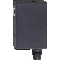
OJ5038 - Photoelectric barrier IFM - Free user manual and instructions
Find the device manual for free OJ5038 IFM in PDF.


User questions about OJ5038 IFM
0 question about this device. Answer the ones you know or ask your own.
Ask a new question about this device
Download the instructions for your Photoelectric barrier in PDF format for free! Find your manual OJ5038 - IFM and take your electronic device back in hand. On this page are published all the documents necessary for the use of your device. OJ5038 by IFM.
USER MANUAL OJ5038 IFM
CE
Operating instructions Through-beam sensor
OJ50xx laser

Contents
1 Preliminary note....3
1.1 Symbols used .... 3
2 Safety instructions .... 3
4 Installation .... 4
4.1 Installation of the supplied mounting fixture ....5
5 Electrical connection....6
6 Setup 6
7 Settings....7
7.1 Setting of the sensitivity with stationary objects* 7
7.2 Setting of the sensitivity with moving objects* 8
7.3 Setting of the maximum sensitivity*......9
7.4 Electronic lock 9
7.5 Programming the output function* 9
8 Operation....10
9 Maintenance, repair and disposal....10
1 Preliminary note
1.1 Symbols used
▶ Instruction
▷ Reaction, result
→ Cross-reference

Important note
Non-compliance can result in malfunctions or interference.

Information
Supplementary note.
2 Safety instructions
According to the cULus approval
Caution - Use of controls or adjustments or procedures other than those specified herein may result in hazardous radiation exposure.

Visible laser light; CLASS 1 LASER PRODUCT.
EN/IEC 60825-1 : 2014
Complies with 21 CFR 1040.10 except for conformance with IEC 60825-1 Ed. 3., as described in Laser Notice No. 56, dated May 8, 2019.
Position of the product label

Additional label

3 Functions and features
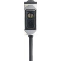
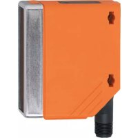
The through-beam sensor detects objects and materials without contact and indicates their presence by a switching signal.
Range: → type label.
4 Installation
Side lens*
Front lens*

1: LED
2: pushbutton (on transmitter without function)
* In the following sections installation and setup are described using the example of the type with front lens.
The functions of the units with side lens are identical.
▶ Secure the receiver (OJELxx) to the bracket.
▶ Align the transmitter (OJSLxx) to the receiver and secure it in the same way.
Maximum range is only possible with precise alignment.

▶ Mount the unit so that the mounting position cannot change (avoid high vibrations!).
Laser units with a very small light spot diameter are highly focussed; the slightest change in the mounting position will result in misalignment.
The optical position of the laser beam may deviate slightly from the mechanical axis. Therefore we recommend using the fine adjustment units E20975 (front lens) or E20976 (side lens) when mounting the laser units.
4.1 Installation of the supplied mounting fixture


- ▶ Secure the mounting fixture with the screws supplied, then slide the unit into the slot of the fixture until the spring clicks home.


▶ To remove the unit press the spring down with a screwdriver and slide the unit out.
5 Electrical connection

The unit must be connected by a qualified electrician.
▶ The national and international regulations for the installation of electrical equipment must be adhered to.
▶ Voltage supply according to EN 50178.
▶ Disconnect power.
▶ Connect the unit as follows:
Receiver DC PNP

Receiver DC NPN

Transmitter DC

Programming of the output function by pushbutton or programming wire ( → 7.5 Programming the output function).
6 Setup
The through-beam sensor is supplied ready to operate (plug & play) set at the max. sensing range. This is sufficient if the through-beam sensor can operate with maximum excess gain. The following setting procedures should only be necessary in less straight-forward applications, for example if partly transparent objects must be detected.
7 Settings
7.1 Setting of the sensitivity with stationary objects*
| 1 | ▶ Go into the programming mode of the unit. ▶ Press for about 2 s until the red LED flashes.  |
| ▷ The red LED goes out; the yellow and green LEDs flash alternately. ▷ The unit is in the programming mode. |
| 2 | Set the sensitivity with object. ▶ Press once.  |
| ▷ The yellow and green LEDs go out for approx. 1 s, then flash again alternately. |
| 3 | Set the sensitivity without object. ▶ Press once.  |
| ▷ The yellow and green LEDs go out for approx. 1 s. ▷ After approx. 3 s the green LED is on. ▷ The unit is in the operating mode. |
Setting steps 2 and 3 can also be carried out in reverse order.
* The sensitivity can also be set in exactly the same way using the programming wire (pin 2 / WH). To activate the functions the programming wire is connected to L+ (pin 1 / BN) for PNP units or to L- (pin 3 / BU) for NPN units for the appropriate time. Feedback: If setting was not successful via the programming wire, the output will switch for 2 s. The unit then passes into the operating mode with the sensitivity being unchanged.

If the setting of the sensitivity is not possible (e.g. object signal and background signal are about the same), the red LED flashes after step 3 for approx. 2 s. The unit then passes into the operating mode with the sensitivity being unchanged.
If the setting button is not activated for 15 minutes during the programming process, the unit passes automatically into the operating mode with the sensitivity being unchanged.
7.2 Setting of the sensitivity with moving objects*
| 1 | Go into the programming mode of the unit. ▶ Press about 2 s until the red LED flashes.  |
| ▷ The red LED goes out; the yellow and green LEDs flash alternately. ▷ The unit is in the programming mode. |
| 2 | ▶ Allow objects to pass through the detection area during the measurement (about 1 s) (number of the objects between min. 8 Hz and max. switching frequency). ▶ Press once. |
| ▷ The yellow and green LEDs go out for approx. 1 s, then flash again alternately. |
| 3 | ▶ Allow objects to pass through the detection area during the measurement (about 1 s) (number of the objects between min. 8 Hz and max. switching frequency). ▶ Press once. |
| ▷ The yellow and green LEDs go out for approx. 1 s. ▷ After approx. 3 s the green LED is on. ▷ The unit is in the operating mode. |
* The sensitivity can also be set in exactly the same way using the programming wire (pin 2 / WH). To activate the functions the programming wire is connected to L+ (pin 1 / BN) for PNP units or to L- (pin 3 / BU) for NPN units for the appropriate time. Feedback: If setting was not successful via the programming wire, the output will switch for 2 s. The unit then passes into the operating mode with the sensitivity being unchanged.

If the setting of the sensitivity is not possible (e.g. object signal and background signal are about the same), the red LED flashes after step 3 for approx. 2 s. The unit then passes into the operating mode with the sensitivity being unchanged.
If the setting button is not activated for 15 minutes during the programming process, the unit passes automatically into the operating mode with the sensitivity being unchanged.
7.3 Setting of the maximum sensitivity*
▶ Go into the programming mode of the unit ( → step 1).
▶ Interrupt the light beam.
▶ Press the setting button twice ( → steps 2 and 3).
* The maximum sensitivity can also be set in exactly the same way using the programming wire (pin 2 / WH). To activate the functions the programming wire is connected to L+ (pin 1 / BN) for PNP units or to L- (pin 3 / BU) for NPN units for the appropriate time.
7.4 Electronic lock
Activate the lock by connecting the programming wire for about 15 s -20 s*.
De-activate the lock by connecting the programming wire again for 15 s - 20 s*.
* To activate the functions the programming wire (pin 2 / WH) is connected to L+ (pin 1 / BN) for PNP units or to L- (pin 3 / BU) for NPN units for the appropriate time.
7.5 Programming the output function*
Press for 10 s. | [IMAGE] | ▷ The red LED starts to flash fast after 2 s. ▷ Then the yellow and green LEDs flash alternately. ▷ After 10 s all LEDs go off, the output function has changed from light-on mode to dark-on mode (or vice versa). |
* The output function can be programmed in exactly the same way using the programming wire (Pin 2 /WH). To activate the functions the programming wire is connected to L+ (pin 1 / BN) for PNP units or to L- (pin 3 / BU) for NPN units for the appropriate time.
8 Operation
▶ Check whether the unit operates correctly.
▷ Display by LEDs.
| Green LED on | Unit is ready for operation. |
| Yellow LED on | Output is switched. |
| Red LED on | Error in object detection, e.g. maladjustment, soiling of the lenses |
| LEDs yellow + red | Flash alternately, 2 Hz: output short-circuited. Flash alternately, 1 Hz: internal fault.(output is not switched). |
9 Maintenance, repair and disposal
▶ Keep the lenses of the sensor free from soiling.
▶ For cleaning do not use any solvents or cleaning agents which could damage the plastic lenses.
▶ Do not try to open the module enclosure. There are no user - serviceable components inside.
Technical data and further information at www.ifm.com → Select your country → Data sheet direct:
- 1 PRELIMINARY NOTE
- 1.1 SYMBOLS USED
- 2 SAFETY INSTRUCTIONS
- 3 FUNCTIONS AND FEATURES
- 4 INSTALLATION
- 4.1 INSTALLATION OF THE SUPPLIED MOUNTING FIXTURE
- 5 ELECTRICAL CONNECTION
- 6 SETUP
- 7 SETTINGS
- 7.1 SETTING OF THE SENSITIVITY WITH STATIONARY OBJECTS
- 7.2 SETTING OF THE SENSITIVITY WITH MOVING OBJECTS
- 7.3 SETTING OF THE MAXIMUM SENSITIVITY
- 7.4 ELECTRONIC LOCK
- 7.5 PROGRAMMING THE OUTPUT FUNCTION
- 8 OPERATION
- 9 MAINTENANCE, REPAIR AND DISPOSAL
Brand : IFM
Model : OJ5038
Category : Photoelectric barrier