JPK48SNXWPS - Fridge JENN-AIR - Free user manual and instructions
Find the device manual for free JPK48SNXWPS JENN-AIR in PDF.

User questions about JPK48SNXWPS JENN-AIR
0 question about this device. Answer the ones you know or ask your own.
Ask a new question about this device
Download the instructions for your Fridge in PDF format for free! Find your manual JPK48SNXWPS - JENN-AIR and take your electronic device back in hand. On this page are published all the documents necessary for the use of your device. JPK48SNXWPS by JENN-AIR.
USER MANUAL JPK48SNXWPS JENN-AIR
For questions about features, operation/performance, parts, accessories, or service, call:
1-800-JENNAIR (1-800-536-6247) or visit our website at www.jennair.com.
In Canada, call: 1-800-JENNAIR (1-800-536-6247), or visit our website at www.jennair.ca.
GUÍA DE INSTALACIÓN
Tools and Parts....5
Location Requirements....6
Electrical Requirements....7
Water Supply Requirements....7
Product Dimensions 8
Tipping Radius....9
Door Swing Dimensions 9
Cabinet and Panel Installation Options....9
Fully Integrated Grille Installation Requirements....10
Standard Integrated Grille Installation Requirements ....11
Panel Kit Installation Requirements....12
Custom Wood Overlay Panels 12
Custom Wood Overlay Panel Dimensions 13
INSTALLATION INSTRUCTIONS.... 13
Unpack the Refrigerator 13
Move the Refrigerator into House 14
Install Anti-Tip Boards 14
Connect the Water Supply 15
Plug in Refrigerator.... 16
Install Side Trims 16
Move Refrigerator to Final Location....17
Level and Align Refrigerator 17
Install Refrigerator and Panels 18
Install Base Grille 23
Complete Installation.... 23
ÍNDICE
Your safety and the safety of others are very important.
We have provided many important safety messages in this manual and on your appliance. Always read and obey all safety messages.

This is the safety alert symbol.
This symbol alerts you to potential hazards that can kill or hurt you and others.
All safety messages will follow the safety alert symbol and either the word "DANGER" or "WARNING."
These words mean:
DANGER
You can be killed or seriously injured if you don't immediately follow instructions.
WARNING
You can be killed or seriously injured if you don't follow instructions.
All safety messages will tell you what the potential hazard is, tell you how to reduce the chance of injury, and tell you what can happen if the instructions are not followed.
WARNING

Tip Over Hazard
Refrigerator is top heavy and tips easily when not completely installed.
Keep doors taped closed until refrigerator is completely installed.
Use two or more people to move and install refrigerator.
Failure to do so can result in death or serious injury.
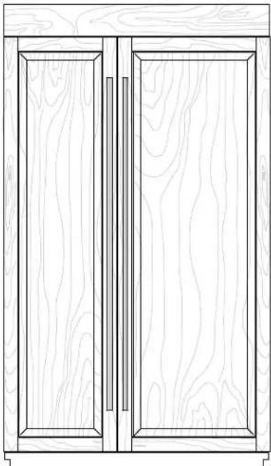
MODELS
natural_image
Line drawing of a double door with wooden grain patterns and vertical bars (no text or symbols)Custom-Made Panel Design
Features custom-made panels and custom hardware provided by the cabinetmaker for a seamless appearance designed to blend with existing kitchen cabinetry.
Base Model Numbers: JS42NXFXDW, JS48NXFXDW
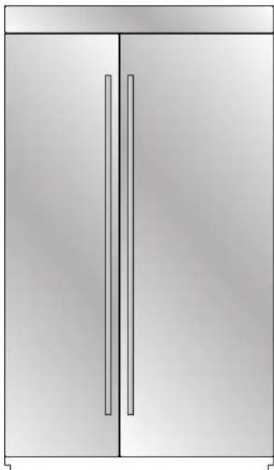
natural_image
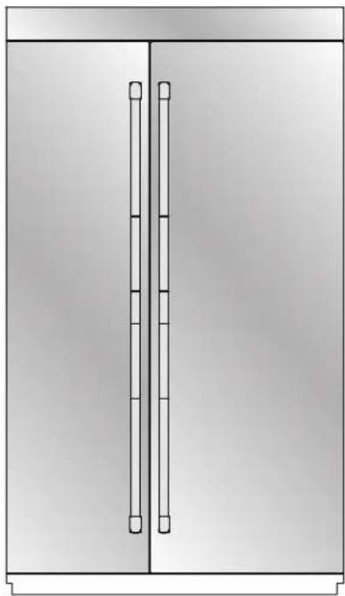
Simple line drawing of a two-door cabinet with vertical bars (no text or symbols)Euro-Style Stainless Design
Features stainless steel wrapped doors with new Euro-style handles designed to compliment the Jenn-Air Euro kitchen suite or enhance any kitchen decor.
Base Model Numbers: JS42NXFXDW, JS48NXFXDW
Kit Model Numbers: JPK42SNXWSS, JPK48SNXWSS
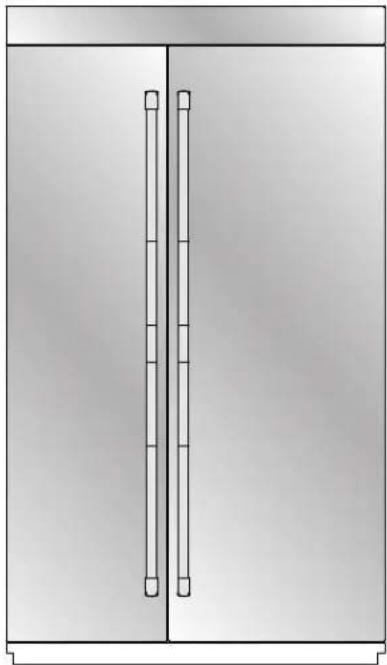
natural_image
Simple line drawing of a two-panel cabinet or enclosure with vertical bars (no text or symbols)Pro-Style® Stainless Design
Features stainless steel wrapped doors and Pro-Style® handles with diamond-etched grip.
Base Model Numbers: JS42NXFXDW, JS48NXFXDW
Kit Model Numbers: JPK42SNXWPS, JPK48SNXWPS
Accessories
All factory parts are available through your Jenn-Air dealer or by calling Jenn-Air at 1-800-JENNAIR (1-800-536-6247). In Canada, call 1-800-807-6777.
Door Handle Kits
For custom wood overlay panels only, handle kits can be ordered. Follow the kit instructions for installation.
IMPORTANT: These handle kits are not intended for use with stainless steel door panel kits.
Pro-Style® Stainless Steel - W10250643
Euro-Style Stainless Steel - W10250640
Classic Euro-Style - W10250637
Armoire-Style Door Panel Kit
Follow the kit instructions for installation.
42" Model - W10292393
48" Model - W10292394
INSTALLATION REQUIREMENTS
Tools and Parts
| IMPORTANT:■ Installer: Leave Installation Instructions with the homeowner.■ Homeowner: Keep Installation Instructions for future reference. Save these Installation Instructions for the local electrical inspector's use. |  Phillips-head flat screw8281251 (28) Phillips-head flat screw8281251 (28) | 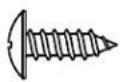 Round-head screw1163283 (24) Round-head screw1163283 (24) | |
| Tools Needed:Gather the required tools and parts before starting installation.Read and follow the instructions provided with any tools listed here.■ Cordless drill■ Drill bits■ Adjustable wrenches (2)■ Phillips screwdriver■ Small level■ 332 " hex key (panel kits only)■ ^1/_32 " nut driver | 38 " and 12 " open-end wrenches 532 " and 316 " hex key 14 " and 516 " socket drivers■ Tape measure■ Utility knife■ Tape (painters)■ Appliance dolly | 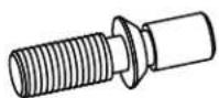 Door Adjustment Pin (preinstalled)W10234194 (2) Door Adjustment Pin (preinstalled)W10234194 (2) | 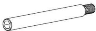 Door Stop PinW10234202 (2) Door Stop PinW10234202 (2) |
| Parts Needed:■ #8 x 3" (7.6 cm) wood screws (longer screws may be needed) (6)■ 2" x 4" x 32" (5 cm x 10 cm x 81 cm) wood boards (2)■ Custom wood overlay panels—consult a qualified cabinetmaker or carpenter to make the custom wood panels.See "Custom Wood Overlay Panels" for more information.ORPanel kit—See "36" Models or 42" French Door Models" for panel kit information.■ Flexible, codes approved water supply tubing, a ferrule, a union and a 14 " (6.35 mm) compression fitting. |  Drawer Panel BracketW10203457 (2) Drawer Panel BracketW10203457 (2) | 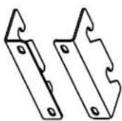 Standard Integrated Grille BracketW10182743—Left (1)W10182741—Right (1) Standard Integrated Grille BracketW10182743—Left (1)W10182741—Right (1) | |
| Parts Provided: | |||
| Slotted hex-head screwW10141645 (21) | Hex-head pointed screwW10141189 (8) | 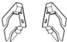 Fully Integrated Grille BracketW10260890—Left (1)W10260891—Right (1) Fully Integrated Grille BracketW10260890—Left (1)W10260891—Right (1) | 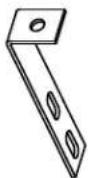 Filler Board "L" BracketW10234199 (2) Filler Board "L" BracketW10234199 (2) |
| Hex-head blunt screwW10142233 (4) | Shoulder washer (use with hex-head pointed screw)W10471946 (4) |  Panel top bracketW10192849 (2) Panel top bracketW10192849 (2) | 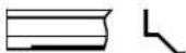 Top Grille Lower TrimW10250961—36" BM (1)W10250962—42" BM, SxS (1)W10250963—48" SxS (1) Top Grille Lower TrimW10250961—36" BM (1)W10250962—42" BM, SxS (1)W10250963—48" SxS (1) |
 |  |
| RC Hinge Cover Trim | FC Hinge Cover Trim |
| W10199873—42" SxSW10199875—48" SxSW10202875—36" BM (Right)W10202510—42" FDBM (Right) | W10199886—42" SxSW10199888—48" SxSW10202877—36" BM (Left)W10202511—42" FDBM (Left) |
 |  |
| Handle Side Door Trim | |
| Panel templates | W10167367—SxSW10188556—BM (Left) |
| W10222281—SxSW10222279—BWM10222283—Grille | W10202604—BM (Right)W10202478—FDBM (Right)W10202480—FDBM (Left) |
 | |
| Installation block | Grille—Bottom / Skirt—Grille |
| W10234156 | W10189198 / W10188549—42" BMW10189196 / W10199547—36" BMW10182718 / W10188551—48" SxSW10182717 / W10188549—42" SxS |
Location Requirements
WARNING

Explosion Hazard
Keep flammable materials and vapors, such as gasoline, away from refrigerator.
Failure to do so can result in death, explosion, or fire.
IMPORTANT:
■ Observe all governing codes and ordinances.
■ It is recommended that you do not install the refrigerator near an oven, radiator, or other heat source.
■ Do not install in a location where the temperature will fall below 55^ F ( 13^ C).
■ Floor must support the refrigerator weight, more than 600 lbs (272 kg), door panels and contents of the refrigerator. Flooring under refrigerator must be at same level as the room. Face of cabinetry must be plumb.
■ Ceiling height must allow for side tipping radius. See “Tipping Radius.”
■ Location should permit door to open fully. See “Door Swing Dimensions.”
■ Location must permit top grille removal. See “Opening Dimensions.”
Opening Dimensions
IMPORTANT:
■ The width of the opening (Width A), from side to side, must be as specified for your model, for at least 2" (5.08 cm) back from the face of the cabinet.
NOTE: If your opening does not meet this requirement, you will need to make modifications.
A solid soffit or wall cabinet must be installed 84" (213.4 cm) above the floor. If the solid soffit is higher than 84" (213.4 cm) or one is not available, then the refrigerator must be braced.
If the anti-tip boards are needed, they must be attached to the rear wall studs so that there is 84" (213.4 cm) from the bottom of the anti-tip board to the floor. See "Install Anti-Tip Boards" for more information.
For a fully integrated installation, a minimum of 6" (15.24 cm) of open space above the refrigerator is required. See "Fully Integrated Installation." Anti-tip boards are required. See "Install Anti-Tip Boards" for more information.
A grounded 3 prong electrical outlet should be located within a specified number of inches from the right-hand side cabinets or end panel. See the chart following the graphic for the number of inches required for your model. For more information, see "Electrical Requirements."
■ The water shutoff should be located in the base cabinet on either side of the refrigerator or some other easily accessible area. If the water shutoff valve is not in the cabinets, the plumbing for the water line can come through the floor. See "Water Supply Requirements" for more information.
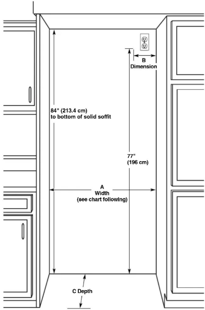
text_image
84" (213.4 cm) to bottom of solid soffit 77" (196 cm) A Width (see chart following) C Depth Dimension B| Model | Width A (as shown above) | Dimension B (as shown above) |
| 42 | 42" (106.7 cm) | 10" (25.4 cm) |
| 48 | 48" (121.9 cm) | 16" (40.6 cm) |
| Installation Type Depth C (as shown above) | |
| Standard Flush (new installation) | 25" (63.5 cm) minimum |
| Retrofit Installations 24" (60.9 cm) minimum | |
Electrical Requirements
WARNING

Electrical Shock Hazard
Plug into a grounded 3 prong outlet.
Do not remove ground prong.
Do not use an adapter.
Do not use an extension cord.
Failure to follow these instructions can result in death, fire, or electrical shock.
Before you move your refrigerator into its final location, it is important to make sure you have the proper electrical connection.
Recommended Grounding Method
A 115 volt, 60 Hz., AC only, 15- or 20-amp fused, grounded electrical supply is required. It is recommended that a separate circuit serving only your refrigerator be provided. Use an outlet that cannot be turned off by a switch. Do not use an extension cord.
IMPORTANT: If this product is connected to a GFCI (Ground Fault Circuit Interrupter) protected outlet, nuisance tripping of the power supply may occur, resulting in loss of cooling. Food quality and flavor may be affected. If nuisance tripping has occurred, and if the condition of the food appears poor, dispose of it.
NOTE: Before performing any type of installation, cleaning, or removing a light bulb, remove the top grille and turn the master power switch to OFF or disconnect power at the circuit breaker box.
When you are finished, turn ON the master power switch or reconnect power at the circuit breaker box. Then reset the control to the desired setting.
Water Supply Requirements
IMPORTANT:
■ All installations must meet local plumbing code requirements.
There is not enough clearance to achieve a flush installation if a water shutoff valve is located in the wall behind the refrigerator.
■ The water shutoff should be located in the base cabinet on either side of the refrigerator or some other easily accessible area. The water supply line, however, must come up through the floor in the gray shaded area shown.
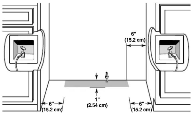
text_image
6" (15.2 cm) 6" (15.2 cm) 1" (2.54 cm) 6" (15.2 cm)■ A 12 " (12.7 mm) hole for plumbing should be drilled on the floor at least 6" (15.2 cm) from the right or left hand side cabinet and should be no more than 1" (2.54 cm) away from the back wall. See "Connect the Water Supply."
■ The water supply connection is made at the front of the refrigerator.
If additional tubing is needed, use copper tubing and check for leaks. Install the copper tubing only in areas where the household temperatures will remain above freezing.
■ Do not use a piercing-type or 315 " (4.76 mm) saddle valve which reduces water flow and clogs more easily.
NOTE: Your refrigerator dealer has a kit available with a 14 " (6.35 mm) saddle-type shutoff valve, a union, and copper tubing. Before purchasing, make sure a saddle-type valve complies with your local plumbing codes.
Water Pressure
A cold water supply with water pressure between 30 and 120 psi (207 and 827 kPa) is required to operate the water dispenser and ice maker. If you have questions about your water pressure, call a licensed, qualified plumber.
Reverse Osmosis Water Supply
IMPORTANT: The pressure of the water supply coming out of a reverse osmosis system going to the water inlet valve of the refrigerator needs to be between 30 and 120 psi (207 and 827 kPa).
If a reverse osmosis water filtration system is connected to your cold water supply, the water pressure to the reverse osmosis system needs to be a minimum of 40 to 60 psi (276 to 414 kPa). If the water pressure to the reverse osmosis system is less than 40 to 60 psi (276 to 414 kPa):
■ Check to see whether the sediment filter in the reverse osmosis system is blocked. Replace the filter if necessary.
- Allow the storage tank on the reverse osmosis system to refill after heavy usage.
If your refrigerator has a water filter, it may further reduce the water pressure when used in conjunction with a reverse osmosis system. Remove the water filter cartridge.
If you have questions about your water pressure, call a licensed, qualified plumber.
Product Dimensions
IMPORTANT:
■ The depth from the front face of the doors to the back of the refrigerator cabinet is 24" (60.96 cm) without panels.
■ The power cord is 84" (213 cm) long.
■ The water supply connection is made at the bottom front of the refrigerator.
Top View
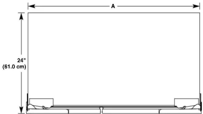
text_image
A 24" (61.0 cm)Model A
42 41 ^3/4 " (106 cm)
48 47 ^3/4 " (121.3 cm)
Front View
■ Width dimensions were measured from hinge to hinge.
■ When leveling legs are fully extended to 1¼" (3.2 cm) below rollers, add 1¼" (2.9 cm) to the height dimensions.
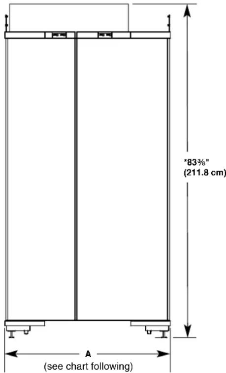
text_image
"83%" (211.8 cm) A (see chart following)Model Width A (hinge edge to hinge edge)
42 41 ^3/4 " (106 cm)
48 47 ^3/4 " (121.3 cm)
Tipping Radius
Be sure there is adequate ceiling height to stand the refrigerator upright when it is moved into place.
■ The dolly wheel height must be added to the tipping radius when a dolly is used.
Side Tipping Radius
The side tipping radius varies depending upon the width of the model. Use the chart provided to determine the side tipping radius.
NOTE: Tip on side only.
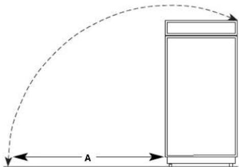
natural_image
Simple line drawing of a cabinet with an arc indicating direction, labeled 'A' at the bottom (no text or symbols on the diagram itself)Model Tipping Radius A
| 42 | 91 38 ′′ (232.1 cm) |
| 48 | 94 38 ′′ (239.7 cm) |
Door Swing Dimensions
The location must permit both doors to open to a minimum of 90°. Allow 4½" (11.4 cm) minimum space between the side of the refrigerator and a corner wall.
NOTE: More clearance may be required if you are using wood overlay panels, custom handles, or extended handles.
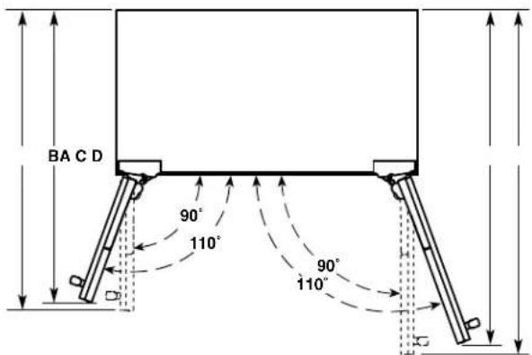
text_image
BA C D 90° 110° 90° 110°Model A B C D
| 42 40 34 " | (103.5 cm) | 39 34 " (101.0 cm) | 45 58 " (115.3 cm) | 46 34 " (118.8 cm) |
| 48 43 14 " | (109.9 cm) | 42" (106.7 cm) | 48 58 " (123.5 cm) | 50 14 " (127.6 cm) |
Cabinet and Panel Installation Options
NOTE: Graphics shown below illustrate installation configuration options given the specified cabinet depths. All possible configurations are not shown.
Cabinet Depth—25" (63.5 cm)
Framed Cabinetry
Top View
text_image
A B C D E FA. Refrigerator door
B. Door panel
C. Side trim
D. Adjacent cabinet
E. Flush return filler
F. 25" (63.5 cm)
Inset
Top View
text_image
A B C D E FA. Refrigerator door
B. Door panel
C. Side trim
D. Adjacent cabinet
E. Flush return filler
F. 25" (63.5 cm)
Frameless Cabinetry
Top View
text_image
A B C D EA. Refrigerator door
B. Door panel
C. Side trim
D. Adjacent cabinet
E. 25" (63.5 cm)
Cabinet Depth—24" (60.9 cm)
NOTE: A flush installation is not possible with a 24" (60.9 cm) deep opening.
Framed Cabinetry
Top View
text_image
A B C D E FA. Refrigerator door
D. Adjacent cabinet
B. Door panel
E. Flush return filler
C. Side trim
F. 24" (60.9 cm)
Frameless Cabinetry
Top View
text_image
A B C D EA. Refrigerator door
D. Adjacent cabinet
B. Door panel
E. 24" (60.9 cm)
C. Side trim
Fully Integrated Grille Installation Requirements
The refrigerator can be installed fully integrated if the adjacent cabinetry meets the airflow venting requirements critical to refrigerator performance. A Fully Integrated Grille installation has no visible air gap because the grille extends upward to the soffit or upper cabinet.
IMPORTANT:
■ A Fully Integrated Grille installation requires a minimum of 6" (15.24 cm) of open space above the refrigerator. This space must not be blocked in any way, including by soffits.
■ Both Standard and Fully Integrated Grille installations can be achieved with either a 24" (60.9 cm) or 25" (63.5 cm) deep opening.
■ A full height grille is used to achieve a Fully Integrated Grille installation. Use the integrated bracket (provided with refrigerator) to attach the full height grille.
NOTE: A top grille filler is not required with a full height grille.
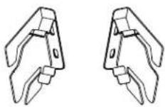
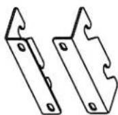
Integrated Grille Bracket
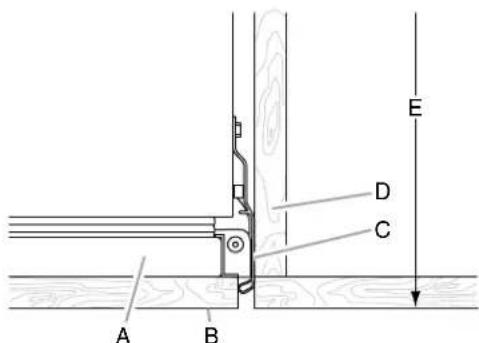
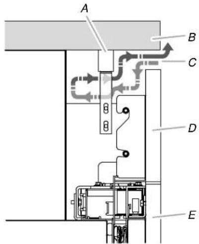
Fully Integrated Grille Installation—Side View
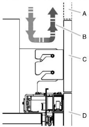
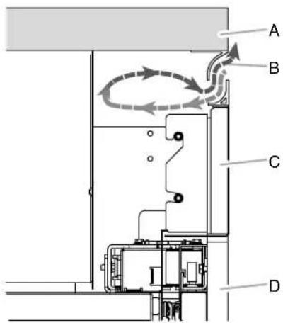
text_image
A B C DA. False front (optional)
B. Airflow
C. Full height grille
D. Door panel
Fully Integrated Grille Installation Options
Option 1—Open to Ceiling
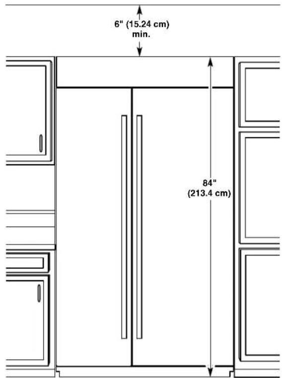
text_image
6" (15.24 cm) min. 84" (213.4 cm)Option 2—False Front (cabinet face only)
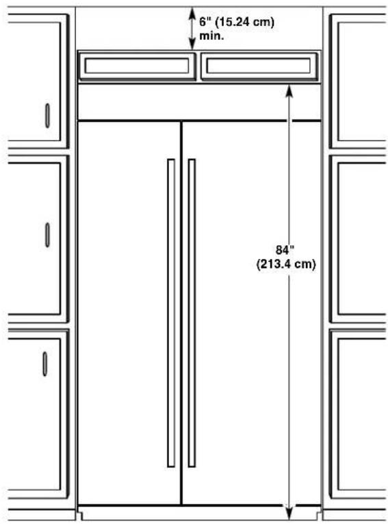
text_image
6" (15.24 cm) min. 84" (213.4 cm)Standard Integrated Grille Installation Requirements
IMPORTANT:
■ A Standard Integrated Grille installation can be achieved with either a 24" (60.9 cm) or 25" (63.5 cm) deep opening.
■ Use the standard grille bracket (provided with refrigerator) to attach the standard grille.
■ The grille panel height, shown in the "Standard Integrated Grille Installation—Side View" graphic, allows for an air gap critical to refrigerator performance.
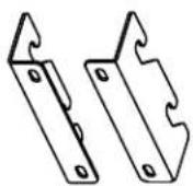
Standard Grille Bracket
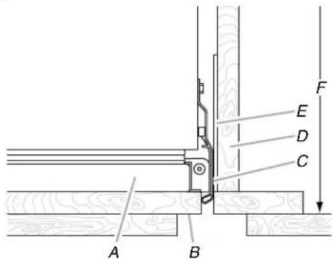
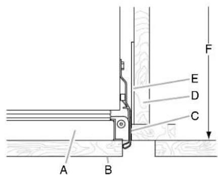
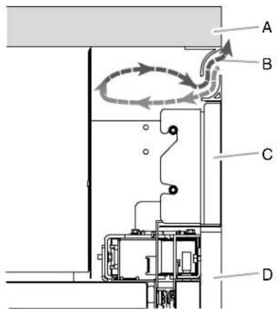
Standard Integrated Grille Installation—Side View
text_image
A B C D EA. Top grille filler
D. Grille panel
B. Soffit
E. Door panel
C. Airflow
Standard Integrated Grille Installation—Full Product View
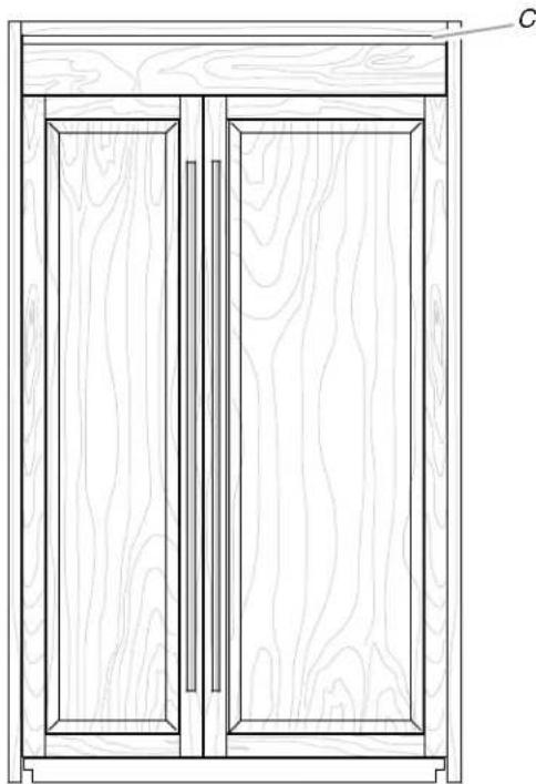
natural_image
Line drawing of a two-door wooden cabinet with wood grain patterns and a side panel labeled C (no text or symbols)C. Airflow
Panel Kit Installation Requirements
See the "Models" section to see the panel kit options available for your model.
IMPORTANT:
■ A panel kit installation can be achieved with either a 24" (60.9 cm) or 25" (63.5 cm) deep opening.
■ A standard grille is used to achieve a panel kit installation. Use the standard grille bracket (provided with refrigerator) to attach the standard grille.
■ The grille panel height, shown in the "Panel Kit Installation—Side View" graphic, allows for an air gap critical to refrigerator performance.
Standard Grille Bracket
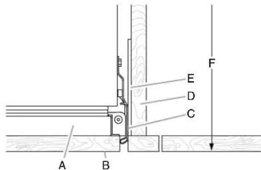
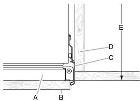
Panel Kit Installation—Side View
text_image
A B C DA. Soffit
C. Grille panel
B. Airflow
D. Door panel
Panel Kit Installation—Full Product View
natural_image
Simple line drawing of a two-panel cabinet or enclosure with vertical connectors (no text or symbols)Custom Wood Overlay Panels
Custom wood overlay panels allow you to blend the exterior of your refrigerator into the overall kitchen décor, and to use custom handles for additional design flexibility.
In some cases, your cabinet manufacturer may choose to work with one panel routed for the different dimensions. Follow these panel dimension and placement instructions to be sure that the custom wood overlay panels will fit properly.
IMPORTANT:
■ The weight of the refrigerator door wood overlay panel cannot exceed 66 lbs (29.9 kg) for 48" models or 65 lbs (29.5 kg) for 42" models.
■ The weight of the freezer door wood overlay panel cannot exceed 50 lbs (23 kg) for 48" models or 49 lbs (22.2 kg) for 42" models.
■ The weight of the top grille wood overlay panel cannot exceed 8 lbs (3.6 kg) for 48" models or 7 lbs (3.2 kg) for 42" models.
■ The required thickness for all panels is 34 " (1.91 cm).
■ This installation does not require filler or backer panels.
Custom Wood Overlay Panel Dimensions
Door Panels
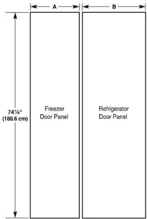
text_image
A B 74¼" (188.6 cm) Freezer Door Panel Refrigerator Door PanelCAUTION
Pinch Hazard
Installation of door panels with less than a 38 " (0.95 cm) gap between the door panel and the adjacent cabinet increases the risk of potential pinching.
Model 42 48
| Reveal | 3/8" | 1/8" | 3/8" | 1/8" |
| A 17916" | (44.61 cm) | 17^13/_16" (45.24 cm) | 20^1/_16" (50.96 cm) | 20^5/_16" (51.59 cm) |
| B 23916" | (59.85 cm) | 23^13/_16" (60.48 cm) | 27^1/_16" (68.74 cm) | 27^5/_16" (69.37 cm) |
Grille Panel
Fully Integrated Grille Installation—Full Height Grille—Open Soffit
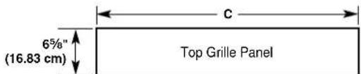
text_image
6%" (16.83 cm) Top Grille Panel CModel 42 48
| Reveal | 38'' | 18'' | 38'' | 18'' |
| C | 41 14'' (104.78 cm) | 41 34'' (106.05 cm) | 47 14'' (120.02 cm) | 47 34'' (121.29 cm) |
Standard Grille Installation—Flush Grille—Open or Closed Soffit
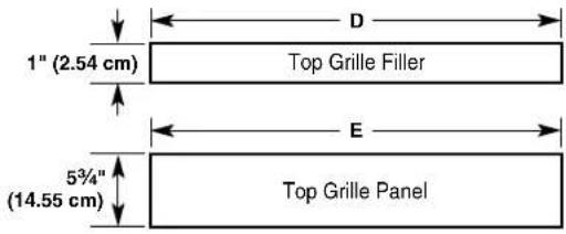
text_image
1" (2.54 cm) Top Grille Filler 5¾" (14.55 cm) Top Grille Panel| Model 42 | 48 | |||
| Revea I | ^3/_8'' | ^1/_8'' | ^3/_8'' | ^1/_8'' |
| D | 41 ^1/_4'' (104.78 cm) | 41 ^3/_4'' (106.05 cm) | 47 ^1/_4'' (120.02 cm) | 47 ^3/_4'' (121.29 cm) |
| E | 41 ^1/_4'' (104.78 cm) | 41 ^3/_4'' (106.05 cm) | 47 ^1/_4'' (120.02 cm) | 47 ^3/_4'' (121.29 cm) |
IMPORTANT: The grille panel height, shown in the "Standard Integrated Grille Installation—Side View" graphic, allows for an air gap critical to refrigerator performance.
INSTALLATION INSTRUCTIONS
Unpack the Refrigerator
WARNING

Tip Over Hazard
Refrigerator is top heavy and tips easily when not completely installed.
Keep doors taped closed until refrigerator is completely installed.
Use two or more people to move and install refrigerator.
Failure to do so can result in death or serious injury.
IMPORTANT:
■ Do not remove the film covering until the refrigerator is in its operating location.
■ All four leveling legs must contact the floor to support and stabilize the full weight of the refrigerator.
- Keep the cardboard shipping piece or plywood under the refrigerator until it is installed in the operating location.
- Remove and save the literature package and hardware kit located inside the refrigerator. Remove and save the literature, grille, and trim taped to the outside of the refrigerator.
NOTE: Do not remove tape and door bracing until the refrigerator is in its final location.
Move the Refrigerator into House
WARNING

Tip Over Hazard
Refrigerator is top heavy and tips easily when not completely installed.
Keep doors taped closed until refrigerator is completely installed.
Use two or more people to move and install refrigerator.
Failure to do so can result in death or serious injury.
- Place an appliance dolly under the left side of the refrigerator as shown. Place the corner posts from the packing materials over the trims as appropriate. Slowly tighten the strap.
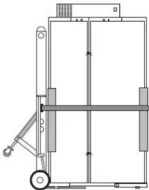
natural_image
Technical line drawing of a mechanical lifting device with wheels and frame (no text or symbols)- Place pieces of the shipping carton on the floor when rolling the dolly and refrigerator into the house. Move the refrigerator close to the built-in opening.
- Place top of cardboard carton or plywood under refrigerator.
- Stand the refrigerator up. First, place the left bottom edge of the refrigerator on the floor, stand the refrigerator upright and then lower the right-hand side of the refrigerator to the floor.
- Reassemble the trim and top grille after the dolly has been removed from the refrigerator.
Install Anti-Tip Boards
IMPORTANT:
■ If a solid soffit is not available, anti-tip boards must be installed.
■ It is recommended that boards be installed before the refrigerator is installed.
■ Boards must be long enough to fully cover the width of the compressor cover.
■ Place the boards so that the bottom surfaces of the boards are 84" (213 cm) from the floor.
■ During installation, raise the refrigerator up until the top of the refrigerator is making contact with the bottom of the anti-tip boards. Do not crush the compressor cover when raising the rear leveling legs.
To Install Anti-tip Boards
- Mark the stud locations on rear wall 80" to 90" (203 cm to 229 cm) above floor.
- Securely attach two 2" x 4" x 32" (5 cm x 10 cm x 81 cm) boards to wall studs behind refrigerator. Use six #8 x 3" (7.6 cm) (or longer) wood screws. The wood screws must be screwed into the studs at least 1½" (3.8 cm). The boards must overlap the compressor cover.
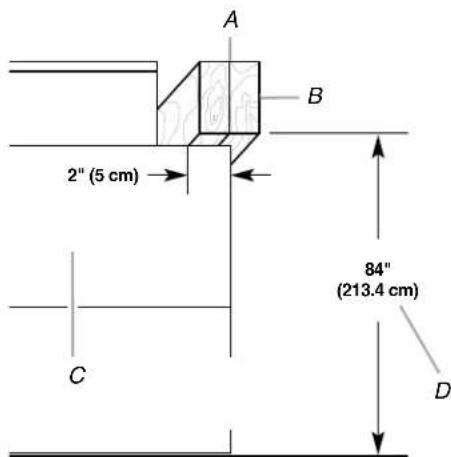
text_image
A B 2" (5 cm) C 84" (213.4 cm) DA. Two 2" x 4" x 32" (5 cm x 10 cm x 81 cm) boards
B. Attach to studs with six #8 x 3" (7.6 cm) screws.
C. Compressor cover
D. Distance from bottom of anti-tip boards to floor
Connect the Water Supply
Read all directions before you begin.
IMPORTANT: If you turn the refrigerator on before the water line is connected, turn the ice maker OFF.
Connect to Water Line
Parts Needed
■ Minimum 7 ft (2.13 m) flexible, codes approved water supply line
Style 1—Shutoff Valve Connection
NOTE: If your water line connection does not look like Style 1, see "Style 2—Copper Line Connection."
- Unplug refrigerator or disconnect power supply.
IMPORTANT:
■ There is not enough clearance to achieve a flush installation if a water shutoff valve is located in the wall behind the refrigerator. The water shutoff should be located in the base cabinet on either side of the refrigerator.
■ Before attaching the tubing to shutoff valve, flush the main water supply line to remove particles and air in the water line. Allow enough flow so that water becomes clear. Flushing the water line may help avoid filters and/or water valves from becoming clogged.
2. Connect the flexible, codes approved water supply line to the water shutoff valve by threading the provided nut onto the shutoff valve as shown.
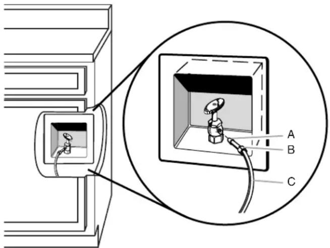
text_image
Technical diagram showing a device with labeled components A, B, and C, including an inset close-up of the internal structure.A. Bulb
B. Nut
C. Water tubing
- Place the end of the tubing into a bucket, and turn shutoff valve ON.
- Check for leaks. Tighten any nuts or connections (including connections at the valve) that leak.
Style 2—Copper Line Connection
NOTE: If there is a water supply line that meets the specifications in “Water Supply Requirements,” proceed to “Connecting to Refrigerator.” If not, use the following instructions to connect to the household cold water supply.
- Unplug refrigerator or disconnect power.
- Turn OFF main water supply. Turn ON nearest faucet long enough to clear line of water.
- Locate a 12 " to 114 " (1.25 cm to 3.18 cm) vertical cold water pipe near the refrigerator.
IMPORTANT:
■ Make sure it is a cold water pipe.
Horizontal pipe will work, but drill on the top side of the pipe, not the bottom. This will help keep water away from the drill and keep normal sediment from collecting in the valve.
- Determine the length of copper tubing you need. Measure from the connection on the refrigerator to the water pipe. Add 7 ft (2.1 m) to allow for cleaning. Use 14 " (6.35 mm) O.D.
(outside diameter) copper tubing. Be sure both ends of copper tubing are cut square. - Using a cordless drill, drill a 14 " (6.35 mm) hole in the cold water pipe you have selected.
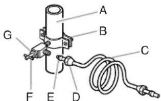
text_image
A B C D E F GA. Cold water pipe
B. Pipe clamp
C. Copper tubing
D. Compression nut
E. Compression sleeve
F. Shutoff valve
G. Packing nut
- Fasten the shutoff valve to the cold water pipe with the pipe clamp. Be sure the outlet end is solidly in the 14 " (6.35 mm) drilled hole in the water pipe and that the washer is under the pipe clamp. Tighten the packing nut. Tighten the pipe clamp screws slowly and evenly so washer makes a watertight seal. Do not overtighten.
IMPORTANT: Before attaching the tubing to shutoff valve, flush the main water supply line to remove particles and air in the water line. Allow enough flow so that water becomes clear. Flushing the water line may help avoid filters and/or water valves from becoming clogged.
- Slip the compression sleeve and compression nut on the copper tubing as shown. Insert the end of the tubing into the outlet end squarely as far as it will go. Screw compression nut onto outlet end with adjustable wrench. Do not overtighten the clamp or the sleeve. This will crush the copper tubing.
- Turn off the shutoff valve on the water pipe. Coil the copper tubing.
- Connect the flexible, codes approved water supply line to the water shutoff valve by threading the provided nut onto the shutoff valve.
- Place the end of the tubing into a bucket, and turn shutoff valve ON.
- Check for leaks around the saddle valve. Tighten any nuts or connections (including connections at the valve) that leak.
Connect to Refrigerator
Parts Supplied
■ 14 " to 14 " (6.35 mm to 6.35 mm) male-to-male coupling
text_image
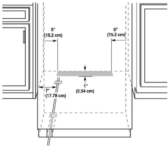
6" (15.2 cm) 6" (15.2 cm) 7" (17.78 cm) 1" (2.54 cm)NOTE: The flexible, codes approved water supply line should connect to the supply valve through the floor.
- Unplug the refrigerator or disconnect power.
- Connect the 7 ft (2.13 m) flexible codes approved water tube to the water supply valve.
- Flush the main water supply line to remove particles and air in the water line. Allow enough flow so that water becomes clear.
- Tape the 7 ft (2.13 m) flexible codes approved water supply line to the floor, 7" (17.78 cm) from the left side of the refrigerator. Tape along the length of the tubing, which will allow it to pass beneath the refrigerator without interference.
NOTE: Allow a minimum of 26" (66.04 cm) of flexible codes approved water supply line to be loose at the front of the refrigerator for connecting to the refrigerator.
- Connect the 7 ft (2.13 m) flexible codes approved water supply line to the refrigerator.
NOTE: If the main water shutoff valve is behind the refrigerator, a secondary water shutoff valve may be installed in line with the water supply line at the front of the product.
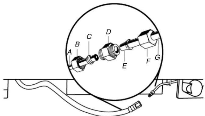
text_image
Technical diagram of a mechanical assembly with labeled components A through G, showing a circular component and wiring connections.A. Household water line
B. Nut (purchased)
C. Ferrule (purchased)
D. Coupling
E. Bulb
F.Nut
G. Refrigerator water tubing
- Turn on the water supply valve and check all connections for leaks.
Plug in Refrigerator
WARNING

Electrical Shock Hazard
Plug into a grounded 3 prong outlet.
Do not remove ground prong.
Do not use an adapter.
Do not use an extension cord.
Failure to follow these instructions can result in death, fire, or electrical shock.
- Set control switch at top of cabinet to the OFF position.
- Plug into a grounded 3 prong outlet.
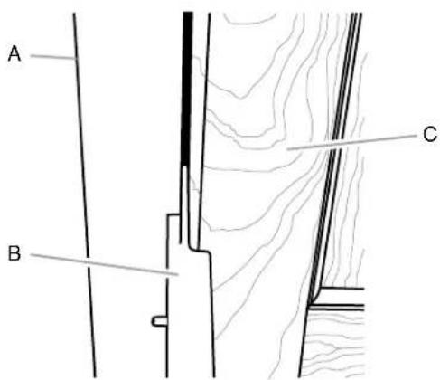
Install Side Trims
The side trims cover the space between the refrigerator and the adjacent cabinets. There is a trim piece taped to each side of the refrigerator. Install each trim piece to the side of the refrigerator to which it is taped.
- Remove the tape attaching the trim pieces to the sides of the refrigerator. Set the trim pieces aside.
IMPORTANT: Custom wood panel (with 18 " gap) installations only - The bulb-shaped edge of the side trim piece will interfere with the panels. Peel the bulb-shaped, long edge from the trim piece and discard. See the "Top View" graphic later in this section.
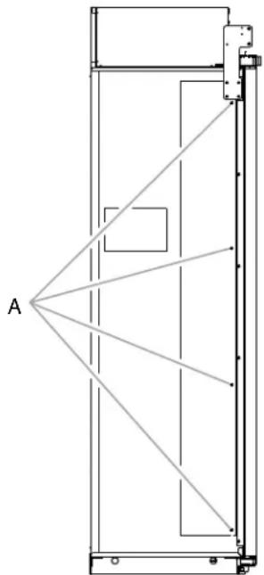
- Remove the four screws from the side of the refrigerator cabinet.
natural_image
Pure technical line drawing of a vertical structure with diagonal lines and labeled point A, no text or symbols present.A. Side trim screws
- Using the original holes and the screws removed in Step 2, fasten the side trim to the refrigerator cabinet.
NOTE: Make sure to fasten each trim piece to the side of the refrigerator cabinet from which it was removed. The bulb-shaped edge should be forward with the notch at the top, as shown.
Top View
text_image
A B C DA. Side trim
B. Adjacent cabinet
C. Door
D. Bulb-shaped edge
Move Refrigerator to Final Location
WARNING

Tip Over Hazard
Refrigerator is top heavy and tips easily when not completely installed.
Keep doors taped closed until refrigerator is completely installed.
Use two or more people to move and install refrigerator.
Failure to do so can result in death or serious injury.
IMPORTANT:
■ A flush installation is NOT possible with a 24" (60.9 cm) deep opening.
■ To avoid floor damage, make sure levelers are raised (not touching floor) and refrigerator is on rollers before moving.
■ Use the installation block, attached to the door hinge, as a reference to make sure the refrigerator is pushed back far enough into the opening, so that when the panels are installed they will be flush with the adjacent cabinets.
■ After the refrigerator is leveled and aligned, remove the installation block from the door hinge and use it to check the spacing between the panels and adjacent cabinets.
NOTE: The installation block is designed to provide accurate spacing for 34 " (1.9 cm), 38 " (9.53 mm) and 18 " (3.18 mm).
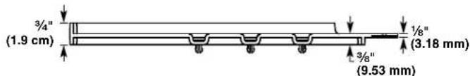
text_image
3/4" (1.9 cm) 3/8" (9.53 mm) 1/8" (3.18 mm)- Place top of cardboard carton or plywood under refrigerator. Remove dolly.
- Move the refrigerator straight back and evenly into the opening. Be sure that the water tubing is not kinked and the power supply cord is on top of the refrigerator.
NOTE: If the power supply cord is behind the refrigerator, it will not install properly.
- Make sure the installation block is flush with the adjacent cabinets.
NOTE: To achieve a flush installation, it is critical to verify a 34 " (1.9 cm) depth from the front face of the adjacent cabinetry to the refrigerator.
text_image
A B C 3/4" (1.9 cm)A. Adjacent cabinet or wall
B. Installation block
C. Face of refrigerator
Level and Align Refrigerator
WARNING

Tip Over Hazard
Refrigerator is top heavy and tips easily when not completely installed.
Keep doors taped closed until refrigerator is completely installed.
Use two or more people to move and install refrigerator.
Failure to do so can result in death or serious injury.
IMPORTANT: All four leveling legs must contact the floor to support and stabilize the full weight of refrigerator. Rollers are for moving the refrigerator, not for permanent support.
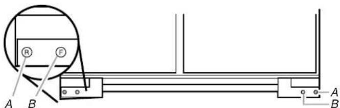
After moving the refrigerator to its final location:
- Use a 516 " socket driver to turn the leveling bolts clockwise to extend the legs to the floor as shown. The rollers should be off the floor.
text_image
A B R F A BA. Rear leveling bolt
B. Front leveling bolt
-
Adjust the leveling legs to level and align the refrigerator from left to right and front to back so that the refrigerator is level and aligned with the cabinets.
-
Continue adjusting the leveling legs until the top of the refrigerator is making contact with the bottom of the solid soffit, or the bottom of the anti-tip boards, if anti-tip boards were used. Do not crush the compressor cover.
IMPORTANT: Adjust in small increments to keep from damaging the cabinet trim and causing problems with the door alignment or top grille fit. To avoid damage to the cabinet or leveling legs, do not apply more than 50 inch-pounds (5.65 Nm) of torque to the leveling bolts. The leveling legs can be extended to a maximum of 1 14 (3.18 cm) below the rollers.
text_image
A B 2" (5 cm) 84" (213.4 cm) C DA. Two 2" x 4" x 32" (5 cm x 10 cm x 81 cm) boards
B. Attach to studs with six #8 x 3" (7.6 cm) screws.
C. Compressor cover
D. Distance from bottom of anti-tip board to floor
- After leveling the refrigerator, again use a straight edge or 4-ft level across the front of the refrigerator installation blocks to the cabinets to check that the refrigerator is still flush.
Install Refrigerator and Panels
IMPORTANT: Jenn-Air is not responsible for the removal or addition of molding or wood overlay panels that would not allow access to the refrigerator for service.
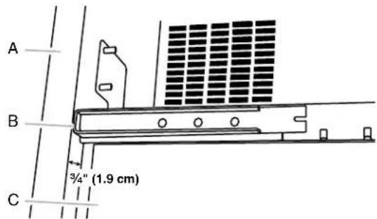
Install Top Grille Filler (standard installation only)
IMPORTANT: The grille panel height allows the necessary airflow for refrigerator performance. The top grille filler hides the upper compartment cover behind the top grille. If you choose to modify the recommended grille panel dimensions, performance will be compromised.
Custom Wood Panel Models
- In the custom made (1" x width of grille panel) wood filler piece, drill a hole 1116 " from each edge.
NOTE: Make sure the hole is centered in the 1" thickness of the wood piece. - Using slotted hex-head screws (provided with refrigerator), fasten an "L" bracket to each end of the wood filler piece.
-
Using hex-head blunt screws (provided with refrigerator), attach the "L" brackets to the top grille mounting plates.
-
Adjust the "L" brackets, so that the wood filler piece is flush with the bottom of the soffit. Completely tighten the screws.
text_image
A B CA. Top grille filler
B. "L" bracket
C. Grille mounting plate
Side View

text_image
A B C D EA. Top grille filler
B. Soffit
C. Airflow
D. Grille panel
E. Door panel
Panel Kit Models
WARNING
Excessive Weight Hazard
Use two or more people to move and install panels.
Failure to do so can result in back or other injury.
-
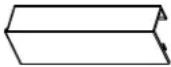
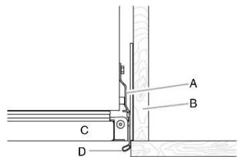
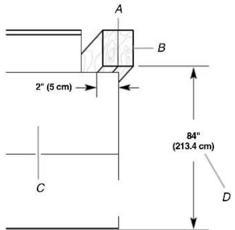
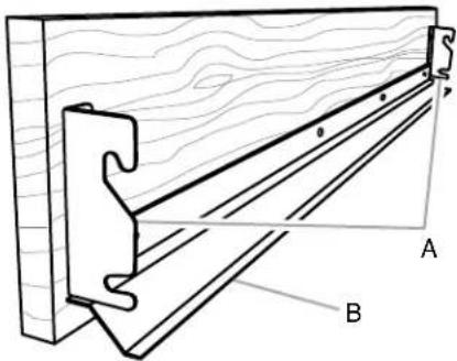
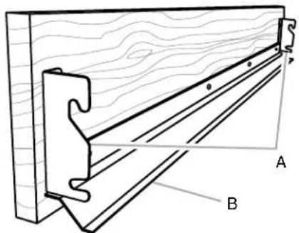
Align top grille vent (provided in the door kit) with the bottom edge of the soffit. Use as a template, and mark where to drill the holes.
-
Using the slotted hex-head screws (provided with refrigerator), attach the top grille vent to the soffit.
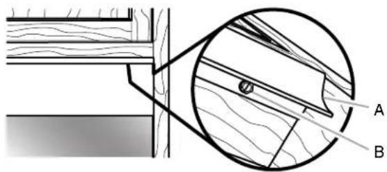
text_image
Technical diagram showing cross-section of a wooden structure with labeled components A and B, including a magnified detail view.A. Top grille vent
B. Slotted hex-head screw
Side View
text_image
A B C DA. Soffit
C. Grille panel
B. Airflow
D. Door panel
Predrill Panels (custom wood panels only)
IMPORTANT: The custom panel template shipped with the refrigerator can be used for either a 38 " (0.95 cm) or a 18 " (0.32 cm) reveal installation.
■ The drilling templates are used only for custom wood overlay panels.
■ The drilling templates are double-sided.
■ The drilling holes are precut into the template.
- On the template, locate the diagram of your refrigerator. Then, follow the letters and colored arrows to correctly place the drilling template on the back side panels.
NOTE: Check the direction of the arrows to determine which holes to mark when the template is aligned at the top of the panel and which holes to mark when the template is aligned at the bottom of the panel.
- Predrill pilot holes into the wood rails bordering the doors and top grille panels.
Prepare Panels (custom wood panels only)
Door Panels
- Place panels on a firm, covered, flat surface with the front facing down.
- Locate the 2 predrilled holes in the handle side edge of the door panel.
- Using the installation block as a guide for depth, attach a shoulder washer with a hex head pointed screw (both provided with refrigerator) into the predrilled door panel (2 per door).
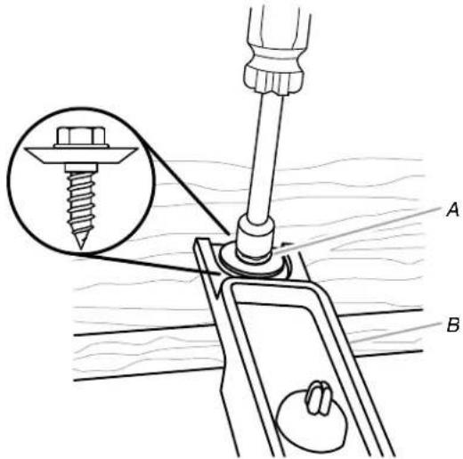
text_image
Technical diagram showing screw installation with labeled parts A and B, including a magnified inset of the screw assembly.A. Shoulder washer and hex head pointed screw
B. Installation block
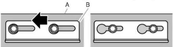
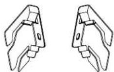
- For the mounting bracket, insert the hex-head pointed screws (provided with refrigerator) into the wood at the top of the door panels where they were predrilled.
NOTE: It is critical to use the 58 " screw, the longest length provided, to attach the bracket to the top of the door panel.
text_image
A BA. U-shaped hole
B. Slot
- Attach a mounting bracket to the top edge of each door panel by placing the large end of the keyhole slot over the screws and sliding the bracket so that the screws are centered in the slots.
NOTE: Start with the screws in the center of the slots as shown, then move the door panel, as necessary, to align.
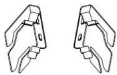
natural_image
Diagram showing two mechanical components labeled A and B with directional arrows indicating movement or force (no text or symbols beyond labels)A. Door panel
B. Mounting bracket
Top Grille Panel
- Using the slotted hex-head screws (provided with refrigerator), attach a mounting bracket to each side of the top grille panel. IMPORTANT: See the "Parts Provided" section to select the brackets designated for your installation.
■ Use the Integrated Grille brackets for a Fully Integrated Grille installation with a full height grille.
■ Use the Standard Grille brackets for a Standard Integrated Grille Installation with a closed or open soffit.
text_image
Technical diagram of a wooden beam joint with labeled components A and BA. Top grille brackets B. White, grille trim piece (taped to refrigerator door)
- Using round-head screws (provided with refrigerator), attach the grille trim piece to the bottom of the grill panel. NOTE: The grille trim is preinstalled on the panel kits.
Remove Trim Pieces
- Remove all tape and door bracing from the refrigerator and freezer doors.
- Open the refrigerator and freezer doors.
- Remove the hinge cover pieces from the top and bottom of the door to expose the holes in the hinges.
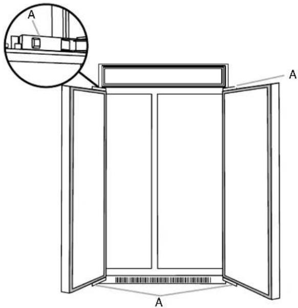
text_image
A A AA. Hinge cover pieces
Install Door Panels
IMPORTANT: Use the foam packaging to prop and hold the door(s) open while installing a door panel.
- Align the two shoulder washers, on the back of the door panel, with the "J" slots on the side of the refrigerator door. Slide the panel onto the door.
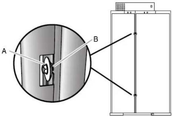
text_image
A BA. Shoulder washer and hex head pointed screw
B. "J" pocket
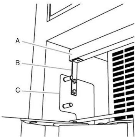
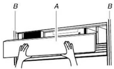
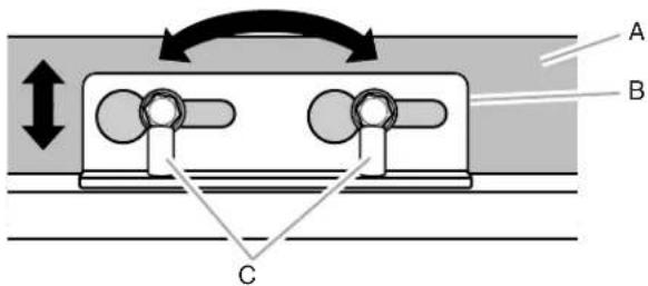
- Lower the panel bracket down onto the adjustment pins at the top of the door.
text_image
A B CA. Door panel
C. Adjustment pins
B. Mounting bracket
- Repeat steps 1 through 2 to install the second door panel.
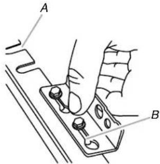
- Using slotted hex-head screws (provided with refrigerator), attach the mounting bracket (factory installed), located at the bottom of the refrigerator and freezer doors, to the respective door panels. Do not fully tighten the screw.
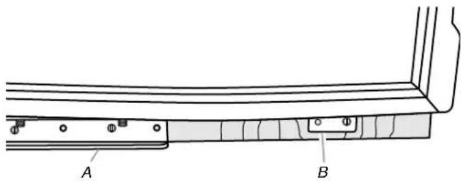
text_image
A BA. Bottom hinge
B. Mounting bracket
Install Top Grille Panel
text_image
B A BA. Top grille panel
B. Cabinet sides
Standard Integrated Grille Installation—Flush Grille
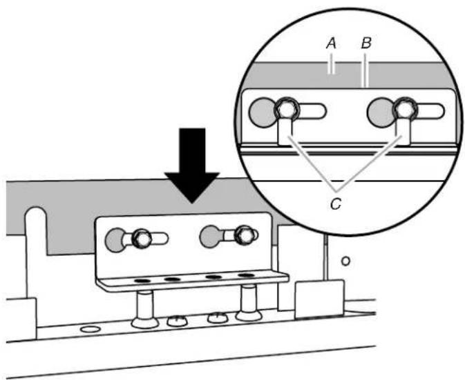
- Hook the panel brackets onto the mounting bolts extending from the top of the refrigerator.
text_image
Technical diagram showing a wooden beam joint with labeled components A and B, including hatching patterns and alignment markers.A. Panel brackets
B. Grill trim piece
- Pull the grille panel down slightly to lock into place.
Fully Integrated Grille Installation—Full Height Grille
- Align the bracket on each side of the top grille panel with the mounting bolts.
- Push the grille panel forward until the bracket snaps into place.
Door Swing Adjustment
It may be necessary to adjust the swing of the door. Make sure the refrigerator door(s) can open freely. If the door(s) opens too wide, install the door stop pin (provided with refrigerator).
- Hold the door open to a position that is less than 90^ .
- Insert the door stop pin into the top hinge in the hole shown.
- Using a 532 " hex key, tighten the door stop pin.
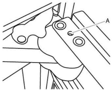
natural_image
Technical line drawing of a mechanical component with labeled point A (no text or symbols beyond label)A. Door stop pin hole
Complete Panel Installation
- Use the installation block to measure the gaps between the panels and adjacent cabinets.
■ Custom wood overlay panels may be made with a 38 " (0.95 cm) or 18 " (0.32 cm) gap between the panel and cabinets and a 18 " (0.32 cm) gap between the freezer and refrigerator door(s) and the door(s) and top grille.
All purchased panel kits require a 38 " (0.95 cm) gap between the panel and the cabinets and a 18 " (0.32 cm) gap between the freezer and refrigerator door(s), and the door(s) and top grille.
text_image
A B CA. Adjacent cabinet
B. Installation block
C. Panel on door
- Adjust the panel to achieve the required spacing, or to align.
IMPORTANT: If adjustments are needed, adjust the panel not the door. Adjust left to right in the mounting bracket before using the pins to adjust the panel up and down or at an angle.
■ Slide the panel from side to side in the keyhole slot.
■ Use a 532 " hex key to raise or lower the adjustment pins which allows the door panel to swivel.
text_image
A B CA. Door panel
B. Mounting bracket
C. Adjustment pins
- Predrill a pilot hole, using an 332 " drill bit, into the door panel through the open holes in both the bottom and top hinges.
- Using slotted hex-head screws (provided with refrigerator), attach the top and bottom hinges to the door panels. Fully tighten all door panel screws.
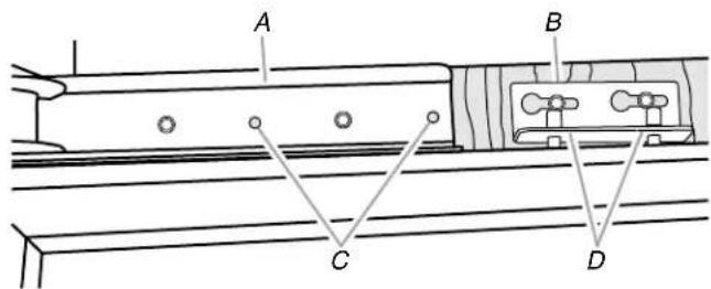
text_image
A B C DA. Top hinge
B. Mounting bracket
C. Holes for screws
D. Adjustment pins
- Using slotted hex-head screws (provided with refrigerator) for each side, attach the door panels to the hinge-side door trims.
- Using Phillips head flat screws (provided with refrigerator), install the handle side door trim.
- Completely tighten the screws attaching the mounting brackets, located at the bottom of the doors, to the overlay panels.
- Reinstall the top door trim and hinge cover.
- Snap the adjustment pin cover (provided with refrigerator) into place.
Install Base Grille
There are two pieces to the base grille to allow for a custom fit: the base grille itself and the skirt. The skirt can be added to the base grille in order to extend it all the way to the floor.
- To see whether the skirt is needed, place the base grille into position. Do not attach the base grille to the refrigerator. Measure the distance between the bottom of the base grille and the floor. The gap must be a minimum of 12 " (1.27 cm) in order to add the skirt.
NOTE: If the gap measures less than 12 " (1.27 cm), skip steps 3 and 4 of the instructions, and install the base grille only.
-
Remove the film from the base grille.
-
Snap the skirt onto the base grille.
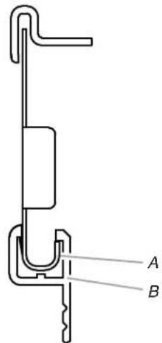
text_image
A BA. Base grille
B. Skirt
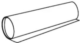
- Trim the skirt by scoring the proper "V" groove with a utility knife. Break the skirt at the score line.
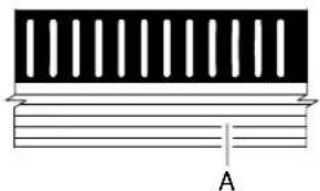
natural_image
Pure diagram of a layered structure with vertical slots and a labeled point A (no text or symbols beyond label)A. "V" groove
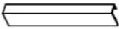
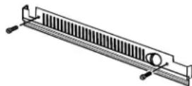
- Using the 2 screws, attach the base grille assembly to the refrigerator as shown.
NOTE: Drive in the right side screw first.
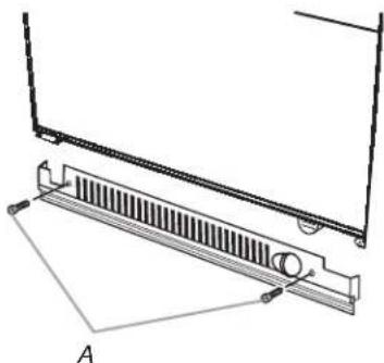
natural_image
Technical line drawing of a mechanical component with a spring-like base and mounting bracket (no text or symbols)A. Screws (2)
Complete Installation
- Turn the water supply line valve to the "Open" position.
- Turn the refrigerator switch to the ON position. See "Power On/Off Switch" in the Use & Care Guide for instructions. Wait a few minutes. Check the water line connections for leaks.
- Remove all boxes, parts packages and packing materials from the interior of the refrigerator. See the "Cleaning" section in the Use & Care Guide for instructions. Remove the film and cardboard from the grille and doors or door frame, depending on your model.
- Install the shelves and bins in the refrigerator and freezer compartments.
- The controls are preset at the factory to the midpoint setting. Check that the compressor is operating properly and that all the lights are working.
- Flush the water system before use. See "Water System Preparation."
To get the most efficient use from your new built-in refrigerator, read the Use & Care Guide. Keep Installation Instructions and Use & Care Guide near the built-in refrigerator for easy reference.
natural_image
Line drawing of a double door with wooden grain patterns and vertical bars (no text or symbols)natural_image
Simple line drawing of a two-door refrigerator with no text or symbols
natural_image
Simple line drawing of a two-panel cabinet or enclosure with vertical bars (no text or symbols)text_image
A 24" (61,0 cm)Modelo A
42 41 ^3/4 " (106 cm)
48 47 ^3/4 " (121,3 cm)
Vista frontal
natural_image
Simple line drawing of a container with an arc indicating motion, labeled 'A' at the bottom (no text or symbols on the diagram itself)natural_image
Line drawing of a wooden double door with visible grain patterns and a labeled component 'C' (no text or symbols beyond label)C. Flujo de aire
natural_image
Simple line drawing of a two-panel cabinet or enclosure with vertical bars (no text or symbols)natural_image
Technical line drawing of a mechanical lifting device with wheels and frame (no text or symbols)text_image
Diagram showing a device with labeled components A, B, and C, including an inset close-up of the component.text_image
A B C D E F Gtext_image
A B C D E F Gnatural_image
Pure technical line drawing of a vertical structure with diagonal lines and labeled point A (no text or symbols beyond label)A. Tornillos de la moldura lateral
text_image
3/4" (1,9 cm) 3/6" (9,53 mm) 1/8" (3,18 mm)text_image
Technical diagram showing a mechanical assembly with labeled parts A and B, including a circular cross-section view.text_image
Technical diagram showing screw installation with labeled parts A and B, including a magnified inset of the screw assembly.natural_image
Diagram showing two views of a mechanical component with labeled points A and B, no text or symbols present.text_image
Technical diagram showing a wooden frame structure with labeled components A and B, including hatching patterns and alignment lines.text_image
Technical diagram showing a wooden beam joint with labeled components A and B, including hatching patterns and alignment lines.A. Soportes del panel
natural_image
Technical line drawing of a mechanical component with labeled point A (no text or symbols beyond label)natural_image
Pure diagram of a layered structure with vertical bars and a labeled point A (no text or symbols beyond label)A. Muesca en "V"
natural_image
Technical line drawing of a mechanical component with a spring-like base and mounting bracket (no text or symbols)A. Tornillos (2)
natural_image
Line drawing of a double door with wooden paneling and vertical divider (no text or symbols)natural_image
Simple line drawing of a two-decker cabinet with vertical bars (no text or symbols)natural_image
Simple line drawing of a two-panel cabinet or enclosure with vertical connectors (no text or symbols)text_image
A 24" (61,0 cm)Modèle A
42 41 ^3/4 " (106 cm)
48 47 ^3/4 " (121,3 cm)
Vue de face
natural_image
Diagram showing a curved dashed arc from left to right, with distance 'A' marked between two vertical rectangles (no text or symbols present)natural_image
Technical line drawing of a two-door wooden cabinet with visible grain patterns and a labeled component 'C' (no text or symbols beyond label)natural_image
Simple line drawing of a two-panel cabinet or enclosure with vertical bars (no text or symbols)natural_image
Technical line drawing of a mechanical lifting device with wheels and frame (no text or symbols)text_image
Diagram showing a device with labeled components A, B, and C, including an inset close-up of the component.text_image
A B C D E F GE. Bague de compression
F. Robinet d'arrêt
G. Écrou de serrage
text_image
A B C D E F Gnatural_image
Pure technical line drawing of a vertical structure with diagonal lines and labeled point A (no text or symbols beyond label)text_image
3/4" (1,9 cm) 3/6" (9,53 mm) 1/8" (3,18 mm)text_image
Technical diagram showing a mechanical assembly with labeled parts A and B, including a circular cross-section view.text_image
Technical diagram showing screw installation with labeled parts A and B, including a magnified inset of the screw assembly.natural_image
Diagram showing two views of a mechanical component with labeled points A and B, no text or symbols present.text_image
Technical diagram showing a wooden beam joint with labeled components A and B, including hatching patterns and alignment lines.natural_image
Technical line drawing of a mechanical component with labeled parts A and B (no text or symbols beyond labels)text_image
Technical diagram showing a wooden beam joint with labeled components A and B, including hatching patterns and alignment lines.A. Supports de panneaux
B. Garniture de grille
natural_image
Technical line drawing of a mechanical component with labeled point A (no text or symbols beyond label)natural_image
Pure electrical circuit lines without any symbolsA. Rainure en V
natural_image
Technical line drawing of a mechanical component with labeled points A and 4, showing no text or symbols beyond labelsA. Vis (2)