
JBBFR30NMX - Refrigerator JENN-AIR - Free user manual and instructions
Find the device manual for free JBBFR30NMX JENN-AIR in PDF.
| Product Type | Built-in Refrigerator with Bottom Freezer |
| Brand | JENN-AIR |
| Model | JBBFR30NMX |
| Dimensions (H x W x D) | 84 in x 30 in x 25 5/8 in (2134 mm x 762 mm x 651 mm) |
| Weight | Approximately 150 kg (330 lb) with packaging |
| Power Supply | 110-120 V AC, 60 Hz, 15 A, dedicated circuit |
| Water Connection | 1/4 in potable water line, 20-120 psi (137.9-827.4 kPa) |
| Refrigerant Type | R-600a (flammable) |
| Refrigerator Capacity | Approximately 19 ft³ (538 L) |
| Freezer Capacity | Approximately 6 ft³ (170 L) |
| Water Filter | Disposable water filter, replace every 6 months |
| Ice Maker | Automatic, 10 cubes per cycle, approximately 100 cubes/24 h |
| Water Dispenser | Interior, with measured fill and integrated filter |
| Lighting | LED inside refrigerator and freezer |
| Shelves | Adjustable tempered glass shelves |
| Drawers | Freezer drawers with telescopic slides, convertible lower drawer |
| Door Bins | Removable and adjustable |
| Controls | Electronic touch screen with temperature settings, Sabbath mode, vacation mode |
| Sabbath Mode | Yes, disables lights and alarms, maintains temperature |
| Cleaning | Clean with mild detergent and warm water; condenser cleanable with a vacuum |
| Warranty | Limited manufacturer warranty (refer to warranty guide) |
| Replacement Parts | Available from authorized after-sales service |
| Built-in Installation | Yes, with 1/8 in (3.2 mm) clearance on each side and top |
| Decorative Panels | Ability to install custom wood panels (thickness 3/4 in to 1 1/8 in) |
| Sound Level | Approximately 38 dB (estimated) - normal operating sounds |
Frequently Asked Questions - JBBFR30NMX JENN-AIR
User questions about JBBFR30NMX JENN-AIR
0 question about this device. Answer the ones you know or ask your own.
Ask a new question about this device
Download the instructions for your Refrigerator in PDF format for free! Find your manual JBBFR30NMX - JENN-AIR and take your electronic device back in hand. On this page are published all the documents necessary for the use of your device. JBBFR30NMX by JENN-AIR.
USER MANUAL JBBFR30NMX JENN-AIR
BOTTOM-MOUNT REFRIGERATOR OWNER'S MANUAL MANUEL D'UTILISATION DU RÉFRIGÉRATEUR AVEC CONGÉLATEUR EN BAS
Table of Contents/Table des matières
REFRIGERATOR SAFETY....2
Refrigerator Safety 2
MAINTENANCE AND CARE 3
Cleaning 3
Changing the LED Module 4
Water Filtration System 4
Vacation and Moving Care 4
Sabbath Mode Instructions ....5
Refrigerator Drawers and Shelves 5
INSTALLATION REQUIREMENTS....6
Tools and Parts 6
Product Dimensions 7
Door Swing Dimensions 7
Site Preparation....7
Location Requirements 8
Electrical Requirements 8
Water Supply Requirements....9
INSTALLATION INSTRUCTIONS 9
Opening Dimensions 9
Unpack the Refrigerator 10
Main Components.... 10
Connect the Water Supply 10
Plug in Refrigerator 11
Move Refrigerator To Final Location.... 12
Refrigerator Doors Panel Mounting.... 13
Leveling.... 21
Install Base Grille.... 21
Complete Installation 22
REFRIGERATOR FEATURES.... 22
Operating Your Refrigerator 22
Water and Ice Dispensers 23
Ice Maker 23
Your safety and the safety of others are very important.
We have provided many important safety messages in this manual and on your appliance. Always read and obey all safety messages.

This is the safety alert symbol.
This symbol alerts you to potential hazards that can kill or hurt you and others.
All safety messages will follow the safety alert symbol and either the word "DANGER" or "WARNING." These words mean:
DANGER
WARNING
You can be killed or seriously injured if you don't immediately follow instructions.
You can be killed or seriously injured if you don't follow instructions.
All safety messages will tell you what the potential hazard is, tell you how to reduce the chance of injury, and tell you what can happen if the instructions are not followed.
IMPORTANT SAFETY INSTRUCTIONS
WARNING: To reduce the risk of fire, electric shock, or injury to persons when using your appliance, follow basic precautions, including the following:
■ Children should be supervised to ensure that they do not play with the appliance.
■ This appliance is not intended for use by persons (including children) with reduced physical, sensory, or mental capabilities, or lack of experience and knowledge, unless they have been given supervision or instruction concerning use of the appliance by a person responsible for their safety.
■ Do not use an extension cord.
If power supply cord is damaged, it must be replaced by the manufacturer, its service agent, or a similarly qualified person in order to avoid a hazard.
■ Connect to potable water supply only.
■ This appliance is intended to be used in household and similar applications such as: staff kitchen areas in shops, offices, and other working environments; farm houses and by clients in hotels, motels, and other residential-type environments; bed and breakfast-type environments; and catering and similar non-retail applications.
■ Do not store explosive substances such as aerosol cans with a flammable propellant in this appliance.
■ Do not use replacement parts that have not been recommended by the manufacturer (e.g., parts made at home using a 3D printer).
- Keep ventilation openings, in the appliance enclosure or in the built-in structure, clear of obstruction.
■ Do not use mechanical devices or other means to accelerate the defrosting process, other than those recommended by the manufacturer.
■ Do not damage the refrigerant circuit.
■ Do not use electrical appliances inside the food storage compartments of the appliance, unless they are of the type recommended by the manufacturer.
■ Ice maker kit can be added to some models. See serial tag inside the food compartment of appliance for ice maker kit model information.
A qualified service technician must install the water line and ice maker. See installation instructions supplied with ice maker kit for complete details.
SAVE THESE INSTRUCTIONS
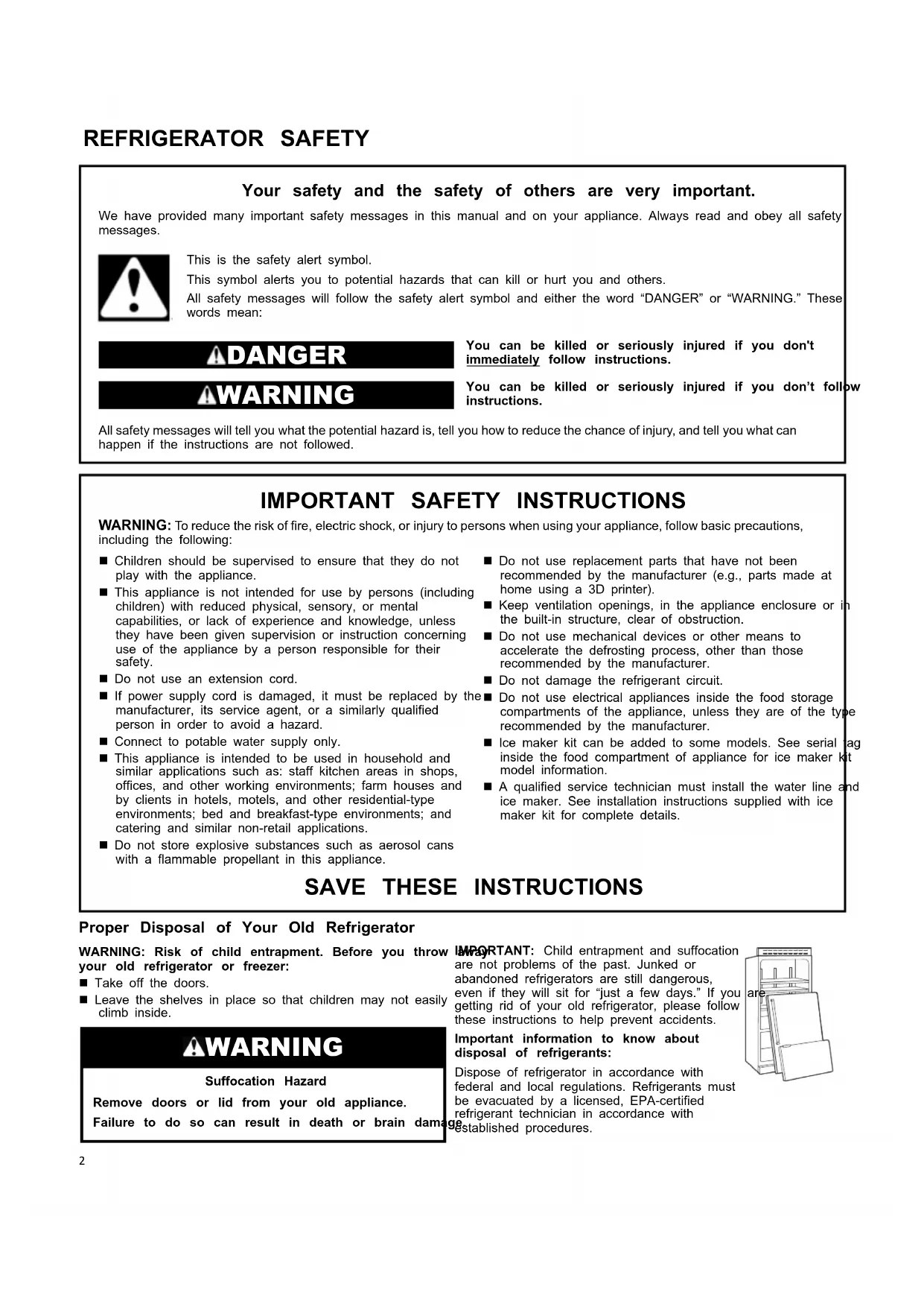
Proper Disposal of Your Old Refrigerator
WARNING: Risk of child entrapment. Before you throw your old refrigerator or freezer:
■ Take off the doors.
■ Leave the shelves in place so that children may not easily climb inside.
WARNING
Suffocation Hazard
Remove doors or lid from your old appliance.
Failure to do so can result in death or brain damage IMPORTANT: Child entrapment and suffocation are not problems of the past. Junked or abandoned refrigerators are still dangerous, even if they will sit for "just a few days." If you getting rid of your old refrigerator, please follow these instructions to help prevent accidents.
Important information to know about disposal of refrigerants:
Dispose of refrigerator in accordance with federal and local regulations. Refrigerants must be evacuated by a licensed, EPA-certified refrigerant technician in accordance with established procedures.
natural_image
Line drawing of a refrigerator with open doors and shelves, labeled 'are' on the cabinet (no other text or symbols)MAINTENANCE AND CARE
Cleaning
WARNING
Explosion Hazard
Risk of Fire or Explosion.
Flammable Refrigerant Used.
Do Not Use Mechanical Devices to Defrost Refrigerator.
Do Not Puncture Refrigerant Tubing.
Both the refrigerator and freezer sections defrost automatically. However, clean both sections about once a month to avoid odor buildup. Wipe up spills immediately.
IMPORTANT:
■ Because air circulates between both sections, any odors formed in one section will transfer to the other. You must thoroughly clean both sections to eliminate odors. To avoid odor transfer and drying out of food, wrap or cover foods tightly.
■ For stainless steel models, stainless steel is corrosion-resistant and not corrosion-proof. To help avoid corrosion of your stainless steel, keep your surfaces clean by using the following cleaning instructions.
To Clean Your Refrigerator:
NOTE: Do not use abrasive or harsh cleaners such as window sprays, scouring cleansers, flammable fluids, muriatic acid, cleaning waxes, concentrated detergents, bleaches, or cleansers containing petroleum products on exterior surfaces (doors and cabinet), plastic parts, interior, and door liners or gaskets. Do not use paper towels, scouring pads, or other harsh cleaning tools.
- Unplug refrigerator or disconnect power.
- Hand-wash, rinse, and dry removable parts and interior surfaces thoroughly. Use a clean sponge or soft cloth and a mild detergent in warm water.
- Clean the exterior surfaces.
Painted metal: Wash painted metal exteriors with a clean, soft cloth or sponge and a mild detergent in warm water. Rinse surfaces with clean, warm water and dry immediately to avoid water spots.
Stainless steel: Wash stainless steel surfaces with a clean, soft cloth or sponge and a mild detergent in warm water. Rinse surfaces with clean, warm water and dry immediately to avoid water spots.
NOTE: When cleaning stainless steel, always wipe with the grain to avoid cross-grain scratching.
Condenser Cleaning
WARNING

Explosion Hazard
Risk of Fire or Explosion due to Puncture of Refrigerant Tubing;
Follow Handling Instructions Carefully.
Flammable Refrigerant Used.
There is no need for routine condenser cleaning in normal home operating environments. If the environment is particularly greasy or dusty, or there is a significant pet traffic in the home, the condenser should be cleaned every 2 to 3 months to ensure maximum efficiency.
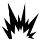
If you need to clean the condenser:
- Unplug refrigerator or disconnect power.
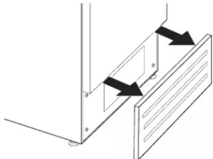
- Remove the base grille.
natural_image
Pure technical diagram showing mechanical components with arrows indicating motion direction (no text or symbols)- Use a vacuum cleaner with a soft brush to clean the grille, the open areas behind the grille, and the front surface area of the condenser.
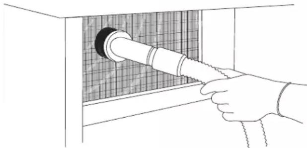
natural_image
Line drawing of a hand inserting a pipe into a grid-patterned cabinet (no text or symbols)- Replace the base grille when finished.
- Plug in refrigerator or reconnect power.
NOTE: If you are unable to clean the condenser, please call for service.
Changing the LED Module

natural_image
Front view of a rectangular appliance with internal fan-like patterns and control panel (no text or symbols)IMPORTANT: The lights in both the refrigerator and freezer compartments use LED technology that do not need to be replaced.
If an LED module(s) do not illuminate when the refrigerator and/or freezer door is opened, call for assistance or service. See "Quick Start Guide" for contact information.
Water Filtration System
The water filter is located above the top glass panel of the refrigerator compartment. To access the water filter hold the top glass panel with two hands, subtle push the glass panel backward. Top glass panel will rotate and lean against the rear wall. Repeat in reverse to put top glass panel back in place.
Do not use with water that is microbiologically unsafe or of unknown quality without adequate disinfection before or after the system. Systems certified for cyst reduction may be used on disinfected waters that may contain filterable cysts.
IMPORTANT: The disposable water filter should be replaced at least every 6 months. If the water flow to the water dispenser or ice maker decreases noticeably before 6 months have passed, replace the water filter more often.
Water Filter Status Lights
The water filter status lights will help you know when to change the water filter. When the Order light is on, it is almost time to change the water filter. When the Replace light is on, a new water filter should be installed.
Reset Water Filter Status
After replacing the water filter, press and hold Filter Reset for 3 seconds until the Order or Replace light turns off. See "Using the Controls" in the Quick Start Guide.
Replacing the Water Filter
natural_image
Simple line drawing of a baby lying in bed with a blanket, no text or symbols presentIMPORTANT: Air trapped in the water system may cause water and filter to eject. Always dispense water for at least 2 minutes before removing the filter or blue bypass cap.
- Turn filter cartridge for quarter rotation in counterclockwise direction to remove.
NOTE: There may be some water in the filter. Some spilling may occur. Use a tower to wipe up any spills. - Remove sealing label from replacement filter and insert the filter end into the filter head.
- Turn the filter clockwise until it stops. Snap the filter cover closed.
- Flush the water system. See "Water Dispenser."
NOTE: The dispenser feature may be used without a water filter installed. Your water will not be filtered. If this option is chosen, push "Water Filter" icon.

Vacation and Moving Care
Vacations
If You Choose to Leave the Refrigerator On While You're Away:
- Use up any perishables and freezer other items.
- If your refrigerator has an automatic ice maker, and is connected to the household water supply, turn off the water supply to the refrigerator. Property damage can occur if the water supply is not turned off.
-
If you have an automatic ice maker, turn off the ice maker. Raise the wire shutoff arm to Off (arm up) position.
-
Empty the ice bin.
If You Choose to Turn Off the Refrigerator Before You Leave
- Remove all food from the refrigerator.
-
If your refrigerator has an automatic ice maker:
■ Turn off the water supply to the ice maker at least one day ahead of time.
■ When the last load of ice drops, raise the wire shutoff arm to the Off (up) position. -
Empty the ice bin.
-
Turn off the Temperature control(s). See "Using the Controls" in the Quick Start Guide.
-
Clean refrigerator, wipe it, and dry well.
-
Tape rubber or wood blocks to the tops of both doors to prop them open far enough for air to get in. This stops odor and mold from building up.
Moving
When you are moving your refrigerator to a new home, follow these steps to prepare it for the move.
-
If your refrigerator has an automatic ice maker:
■ Turn off the water supply to the ice maker at least one day ahead of time.
■ Disconnect the water line from the back of the refrigerator.
■ When the last load of ice drops, raise the wire shutoff arm to the Off (up) position. -
Remove all food from the refrigerator and pack all frozen food in dry ice.
-
Empty the ice bin.
-
Turn off the Temperature control(s). See "Using the Controls" in the Quick Start Guide.
-
Unplug refrigerator.
-
Clean, wipe, and dry thoroughly.
- Take out all removable parts, wrap them well, and tape them together so they don't shift and rattle during the move.
- Depending on the model, raise the front of the refrigerator so rolls more easily or raise the leveling screws so they don't scrape the floor. See online "Adjust the Door(s)" or "Door Closing and Door Alignment."
- Tape the doors closed and tape the power cord to the back the refrigerator.
When you get to your new home, put everything back and refer "Installation Instructions" for preparation instructions. If your refrigerator has an automatic ice maker, remember to reconnect the water supply to the refrigerator.
Sabbath Mode Instructions
Your refrigerator is equipped with the Sabbath Mode feature, which is designed for those whose religious observances require turning off the lights and ice maker.
By selecting this feature:
■ The temperature setpoints settings remain unchanged.
■ LEDs from the electronic controls will not display.
■ The Sabbath button will be the only light displayed.
■ No alarm will ring.
■ Interior lights will turn off.
■ The product will not change its behavior by opening the door.
For the most efficient refrigerator operation, it is recommended to exit Sabbath mode when it is no longer required.
To fully activate Sabbath Mode, you must follow the instructions on the control panel.
CONTROL PANEL
To activate Sabbath mode:
- Choose "settings icon" in the main screen.
- Scroll to the right and locate the "Sabbath Mode Icon" on the second screen (top right). Select the icon.
- A new screen will appear asking if you want the Sabbath Mode On or Off. Choose "ON".
- A new screen will appear asking if you want Sabbath Mode On, Yes or NO. Choose "Yes".
The product will enter Sabbath Mode.
To deactivate Sabbath mode:
- Touch the main screen. It should have "Sabbath Mode" written on it.
- A new screen will appear asking Sabbath Mode On or Off, Choose Off.
- The Sabbath Mode is deactivated and the product will re-start.

Refrigerator Drawers and Shelves Remove and Replace Drawers (for safety reason the removal of drawers is possible only with tools)
Depending on the width of your door opening, it may be necessary to remove the Freezer drawer front to move the refrigerator into your home.
Remove Drawers
- Freezer Drawers are tightened to slide guide with two thumbscrews.
- Open Freezer drawers to its full extension.
- Loosen the two thumbscrews.
- Lift up on the drawer front to release the clips from the drawer slide guide bracket slots.
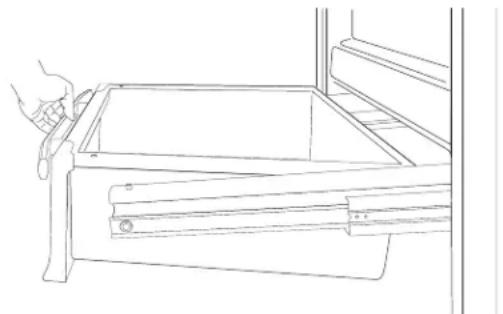
natural_image
Line drawing of a hand using a tool to adjust or install a drawer (no text or symbols present)- Slide the drawer slide guides back into the freezer.
Replace Drawers
- Pull out the drawer slide guides to their full extension.
- Holding drawers front by its sides, align and insert the clips in the drawer guide bracket slots.
NOTE: It helps if one person holds the drawer slide guides steady while another person aligns the drawer front and inserts the clips into the slots.
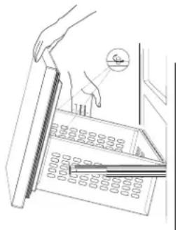
natural_image
Line drawing of a hand holding a ruler placed on an open grid, with a magnified inset showing the scale (no text or symbols)- Replace and tighten the two thumbscrews.
Remove and Replace Ice Tray
Ice tray is located in upper drawer of the freezer compartment.
To remove ice tray:
- Pull out the upper drawer from the freezer compartment.
- Ice tray is attached with locking panels.
- Take out the ice tray by removing locking panels.
To replace ice tray:
- Pull out the upper drawer.
- Align the ice tray with locking panels and place it.
natural_image
Line drawing of a mechanical assembly with a tray and control panel (no text or symbols)Refrigerator Shelves
Important information to know about glass shelves and covers:
Do not clean glass shelves or covers with warm water when they are cold. Shelves and covers may break if exposed to sudden temperature changes or impact, such as bumping. Tempered glass is designed to shatter into many small, pebble-size pieces. This is normal. Glass shelves and covers are heavy. Use both hands when removing them to avoid dropping.
The glass shelves in your refrigerator are adjustable to match your individual storage needs.
Storing similar food items together in your refrigerator and adjusting the shelves to fit different heights of items will make finding the exact item you want easier. It will also reduce the amount of time the refrigerator door is open, and save energy.
Shelves
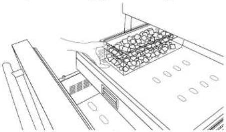
To remove a shelf:
- Remove items from the shelf.
- Hold the glass shelf with both hands, lift and tilt glass shelf release it from the joint in rear part.
- Remove the glass shelf.
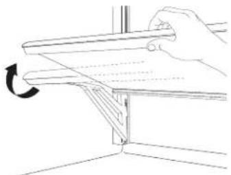
natural_image
Line drawing of a hand holding a metal bracket with a curved arrow indicating rotation (no text or symbols)- To adjust the glass shelves height, tilt the support bracket upward and pull out the bracket on both sides.
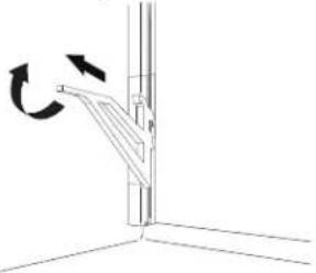
natural_image
Diagram of a mechanical lever mechanism with rotational arrows indicating motion (no text or symbols)- Place the support bracket at required height, slide in the support brackets on both sides. Make sure support brackets are placed at same height.
To replace a shelf:
- Place the glass shelf in the joint of the rear part.
- Lower the front of the glass shelf and make sure that the shelf is in position.
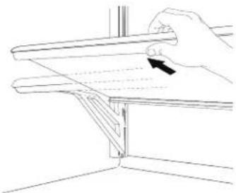
natural_image
Line drawing of a hand holding a metal bracket with an arrow indicating direction (no text or symbols)Door Bins
- Remove the screws and end caps from the top of the door bin support rails.
- Hold the door bin from the sides and tilt it a bit for sliding.
- Push the door bin up to come out of position then pull out.
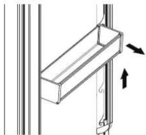
natural_image
Technical diagram of a structural bracket with directional arrows indicating force or movement (no text or symbols)- Hold the door bin at the sides.
- Push the door bin in and then down to fit at required position.
- Reinstall the screws and caps on door bin support rails.
INSTALLATION REQUIREMENTS
Tools and Parts
IMPORTANT:
■ Installer: Leave Installation Instructions with the homeowner.
■ Homeowner: Keep Installation Instructions for future reference. Save these Installation Instructions for the local electrical inspector's use.
Tools Needed:
Gather the required tools and parts before starting installation.
Read and follow the instructions provided with any tools listed here.
Level
■ 11/16" (17 mm) Wrench
■ 3/16" (4 mm) Allen Wrench
■ 3/4" (19 mm) Wrench
■ Phillips Head Screwdriver
■ 2.5 mm Allen Wrench for Handle Set Screws (if applicable)
■ Wood Drill
■ 1/8" (2.5 mm) bit for Wood
■ 5/16" (8 mm) bit for Walls
■ Appliance Dolly
■ Step Ladder
Accessories:
■ Cleaning Kit
■ Spacer Plastic Brackets
■ Anti-tip Kit
■ Lateral Connection Kit
■ Water Filter Kit
■ 90° Stopper
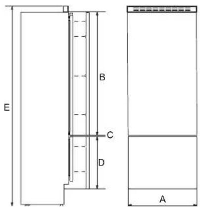
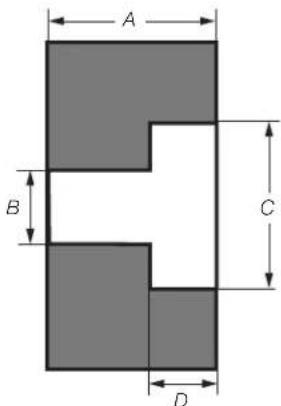
Product Dimensions
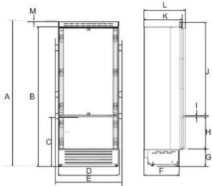
A. 84" (2134 mm)
H. 25 3/8" (645 mm)
B. 81 14 " (2064 mm)
- 1/4" (6 mm)
C. 29 716 " (748 mm)
J. 54 ^3/_16 " (1377 mm)
D. 29 1/2" (749 mm)
K. 24" (610 mm)
E. 29 ^15/16 " (761 mm)
L. 24 3/4" (628 mm)
F. 19 ^11/_16 " (500 mm)
M. 1/8" (3 mm)
G. 4^1/_16 " (103 mm)
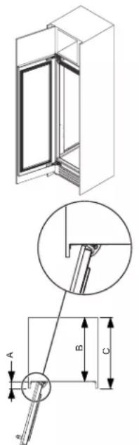
Door Swing Dimensions
The location must permit door to open to a minimum of 90°. Allow 1/4" (15 mm) minimum space between the side of the refrigerator and a corner wall.
NOTE: More clearance may be required if you are using wood overlay panels, custom handles, or extended handles.
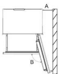
natural_image
Technical diagram of a mechanical assembly with labeled components A and B (no text or symbols present)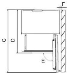
A. 7 ^1/4 " (185 mm)
D. 39" (992 mm)
B. 105^
E. 90°
C. 52 ^9/16 (1335 mm)
F. 1/4" (15 mm)
There is the possibility to limit the opening of the door to 90° by fitting a stopper on the lower hinge.
NOTE: Door Stopper is provided in the accessory bag.
natural_image
Technical line drawing of a mechanical assembly with an inset showing a component detail (no text or symbols)A. Door Stopper
Site Preparation
Anti-Tip Brackets
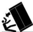
WARNING
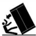
Tip Over Hazard
Refrigerator is top heavy and tips easily when not completely installed.
Keep doors taped closed until refrigerator is completely installed.
Use two or more people to move and install refrigerator.
Failure to do so can result in death or serious injury.
IMPORTANT:
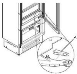
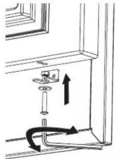
■ For all applications the refrigerator must be braced with the anti-tip brackets supplied.
It is recommended that anti-tip brackets should be attached to the refrigerator before the refrigerator is installed but can be installed after the refrigerator is in the installation location.
To install anti-tip brackets:
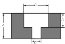
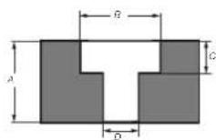
- Area above refrigerator must be clear to attach the anti-tip brackets and identify the stud location within this area A.
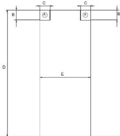
A. Area to be left clear to install Anti-tip brackets
B. 3" (76 mm)
C. 4" (100 mm)
D. 84" (2134 mm) minimum
E. 30" (762 mm)
The minimum gap between the panels and cavity should be 1/16" (1 mm).
-
Anti-tip brackets should be secured by using screws in the wooden frame or concrete when possible. Securing anti-tip brackets to the wall using just expansion plugs should be supplemented with anti-tip boards.
-
The appliance is supplied with the brackets mounted. The edge of the bracket is mounted downwards, during installation turn the edge in upward direction.
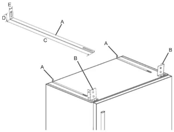
A. Anti-tip brackets
B. Top brackets
C. 20 ^15/_16 " (531 mm)
D. 1^1/2 " (38 mm)
E. 13/16" (20 mm)
Location Requirements
WARNING
Explosion Hazard
Keep flammable materials and vapors, such as gas or away from appliance.
Use nonflammable cleaner.
Failure to do so can result in death, explosion, or fire.
IMPORTANT: This refrigerator is designed for indoor, household use only.
This appliance is intended to be used in a household and similar applications such as:
■ Staff kitchen areas in shops, offices and other working environments.
■ Farm houses and by clients in hotels, motels and other residential type environments.
■ Bed and breakfast type environments.
■ Catering and similar non-retail applications.
To ensure proper ventilation for your refrigerator, allow for 1/8" (3.2 mm) of space on each side and at the top. When installing your refrigerator next to a fixed wall, leave 7 ^1/4 " (185 mm) minimum on the hinge side to allow for the door to swing open.
Electrical Requirements
WARNING

Electrical Shock Hazard
Plug into a grounded 3 prong outlet.
Do not remove ground prong.
Do not use an adapter.
Do not use an extension cord.
Failure to follow these instructions can result in death, fire, or electrical shock.
Before you move your refrigerator into its final location, it is important to make sure you have the proper electrical connection. If the supply cord is damaged, it must be replaced by the manufacturer or its service agent or a similarly qualified person. Do not use a cord that shows cracks or abrasion damage along its length or at either the plug or connector end.
Recommended Grounding Method
A 110 V-120 V, 60 Hz AC only, 15 A fused, grounded electrical supply is required. It is recommended that a separate circuit serving only your refrigerator and approved accessories be provided. Use an outlet that cannot be turned off by a switch. Do not use an extension cord.
NOTE: Before performing any type of installation, cleaning, or removing a light bulb, turn the refrigerator to OFF. Depending on your model, turn the refrigerator control to the word OFF, or press the refrigerator down arrow touch pad until a dash (−) appears in refrigerator displays as shown. Disconnect the refrigerator from the electrical source. When you are finished, reconnect the refrigerator to the electrical source and reset the temperature controls to the desired setting. See "Quick Start Guide."
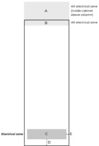
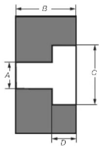
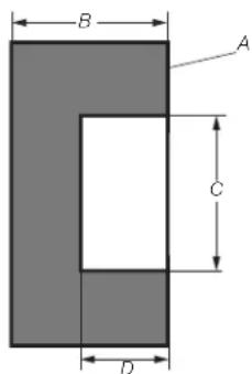
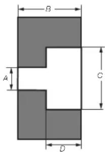
A. 30" width x 12" height
B. 30" width x 3 1/2" height
C. 26 12 " width x /12 " height
D. 4^1/2
E. 1^3/_4
Water Supply Requirements
Gather the required tools and parts before starting installation. Read and follow the instructions provided with any tools listed here.
IMPORTANT:
■ Connect to a potable water supply only.
Do not use with water that is microbiologically unsafe or of unknown quality without adequate disinfection before or after the system. Systems certified for cyst reduction may be used on disinfected waters that may contain filterable cysts.
■ All installations must meet local plumbing code requirements.
■ Do not use a piercing-type or 3/16" (4.76 mm) saddle valve which reduces water flow and clogs more easily.
NOTE: Your refrigerator dealer has a kit available with a 1/4" (6.35 mm) saddle-type shutoff valve, a union, and copper or braided stainless steel or PEX tubing. Before purchasing, make sure a saddle-type valve complies with your local plumbing codes.
- Check for leaks. Install water supply lines only in areas where the household temperatures will remain above freezing.
NOTE: Refrigerator is having 3/4" (19 mm) NPT solenoid connection. It is recommended to use only 1/4" quick connect elbow adapter for 1/4" copper or polyethylene source water line to the refrigerator, or an appropriate NPT adapter.
■ For models with water filters, the disposable water filter should be replaced at least every 6 months.
Water Pressure
A cold water supply with water pressure of between 20 psi and 120 psi (137.9 kPa and 827.4 kPa) is required to operate the water dispenser and ice maker. If you have questions about your water pressure, call a licensed, qualified plumber.
IMPORTANT: Flush the water system before calibrating Measured Fill.
Reverse Osmosis Water Supply
IMPORTANT: The pressure of the water supply coming out of a reverse osmosis system going to the water inlet valve of the refrigerator needs to be between 20 psi and 120 psi (137.9 kPa and 827.4 kPa).
If a reverse osmosis water filtration system is connected to your cold water supply, the water pressure to the reverse osmosis system needs to be a minimum of 20 psi to 120 psi (137.9 kPa to 827.4 kPa).
If the water pressure to the reverse osmosis system is less than 20 psi to 120 psi (137.9 kPa to 827.4 kPa):
- Check to see whether the sediment filter in the reverse osmosis system is blocked. Replace the filter if necessary.
- Allow the storage tank on the reverse osmosis system to refill after heavy usage.
If your refrigerator has a water filter, it may further reduce the water pressure when used in conjunction with a reverse osmosis system. Remove the water filter. See "Water Filtration System".
If you have questions about your water pressure, call a licensed, qualified plumber.
INSTALLATION INSTRUCTIONS
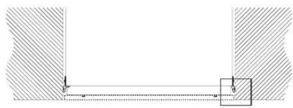
Opening Dimensions
Unpack the Refrigerator
WARNING
Excessive Weight Hazard
Use two or more people to move and install or uninstall appliance.
Failure to do so can result in back or other injury.
Move the refrigerator to the installation structure.
natural_image
Technical line drawing of a cabinet or enclosure structure with no visible text or symbolsRemove the Packaging
Dispose of/recycle all packaging materials. Do not use sharp instruments, rubbing alcohol, flammable fluids, or abrasive cleaners to remove tape or glue. These products can damage the surface of your refrigerator. For more information, see "Refrigerator Safety."
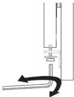
Refrigerator is attached to the packaging base with four bolts. Follow the below steps to release the refrigerator from base.
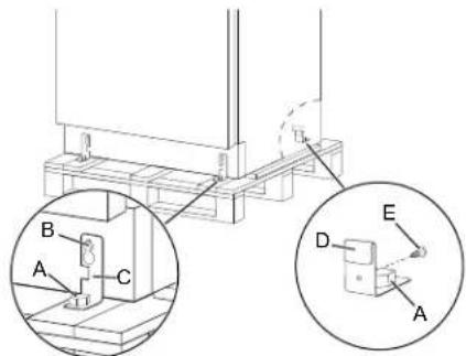
- Unscrew the four bolts (A) by using 3/4" (19 mm) wrench.
- Unscrew the rear wheel adjusting bolt (B) to release the fixing bracket (C) by using 3/4" (19 mm) wrench.
- Remove the screws (E) to release the fixing bracket (D).
- Remove the fixing brackets (C) and (D).
When Moving Your Refrigerator:
Your refrigerator is heavy. When moving the refrigerator for cleaning or service, be sure to cover the floor with cardboard or hardboard to avoid floor damage. Always pull the refrigerator straight out when moving it. Do not wiggle or "walk" the refrigerator when trying to move it, as floor damage could occur.
IMPORTANT: All four leveling legs must contact the floor to support and stabilize the full weight of the refrigerator.
Clean Before Using
After you remove all of the package materials, clean the inside of your refrigerator before using it. See the "Cleaning" section in this manual.
Important information to know about glass shelves and covers:
Do not clean glass shelves or covers with warm water when the are cold. Shelves and covers may break if exposed to sudden temperature changes or impact, such as bumping. Tempered glass is designed to shatter into many small, pebble-size pieces. This is normal. Glass shelves and covers are heavy. Use both hands when removing them to avoid dropping.
Main Components
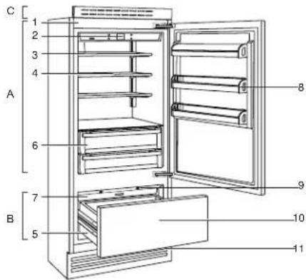
A. Refrigerator
B. Freezer Compartment
C. Top Front Protection Grill
- Galvanized painted body
- Interactive control panel
- Water filter (*)
- Adjustable shelves
- Drawers in freezer compartment
- Drawers refrigerator compartment
- Ice maker container (*)
- Door bins
- LED illuminations for the freezer compartment bottom drawer
- Freezer bottom drawer compartment convertible into refrigerator compartment
- Removable grill condenser
(*) on models with Ice Maker
Connect the Water Supply
Read all directions before you begin.
IMPORTANT:
■ Plumbing shall be installed in accordance with the International Plumbing Code and any local codes and ordinances.
■ The gray water tubing on the back of the refrigerator (which is used to connect to the household water line) is a PEX (crosslinked polyethylene) tube. Copper, stainless steel braided and PEX tubing connections from the household water line to the refrigerator are acceptable, and will help avoid off-taste or odor in your ice or water. Check for leaks. If PEX tubing is used instead of copper.
■ Install tubing only in areas where temperatures will remain above freezing.
■ Connect to a potable water supply only.
Do not use with water that is microbiologically unsafe or of unknown quality without adequate disinfection before or after the system. Systems certified for cyst reduction may be used on disinfected waters that may contain filterable cysts.
NOTE: Your refrigerator dealer has a kit available with a 1/4" (6.35 mm) saddle-type shutoff valve, a union, and copper or PEX tubing. Before purchasing, make sure a saddle-type valve complies with your local plumbing codes. Do not use a piercing type or 3/16" (4.76 mm) saddle valve which reduces water flow and clogs more easily.
Connect to Water Line
IMPORTANT: If you turn on the refrigerator before the water line is connected, turn off the ice maker.
- Unplug refrigerator or disconnect power.
- Turn off main water supply. Turn on nearest faucet long enough to clear line of water.
- Use a quarter-turn shutoff valve or the equivalent, supplied by a 1/2" copper or PEX household supply line.
NOTE: To allow sufficient water flow to the refrigerator, a minimum 1/2" size copper or PEX household supply line is recommended.
- Now you are ready to connect the copper or PEX tubing to the shutoff valve. Use 1/4" (6.35 mm) O.D. (outside diameter) soft copper or PEX tubing to connect the shutoff valve and the refrigerator.
■ Ensure that you have the proper length needed for the job. Be sure both ends of the copper tubing are cut square.
■ Slip compression sleeve and compression nut onto copper tubing as shown. (PEX tubing has compression sleeves and compression nuts pre installed.) Insert end of tubing into outlet end squarely as far as it will go. Screw compression nut onto outlet end with adjustable wrench. Do not overtighten.
- Place the free end of the tubing into a container or sink, and turn on main water supply to flush out tubing until water is clear. Turn off shutoff valve on the water pipe.
NOTE: Always drain the water line before making the final connection to the inlet of the water valve, to avoid possible water valve malfunction.
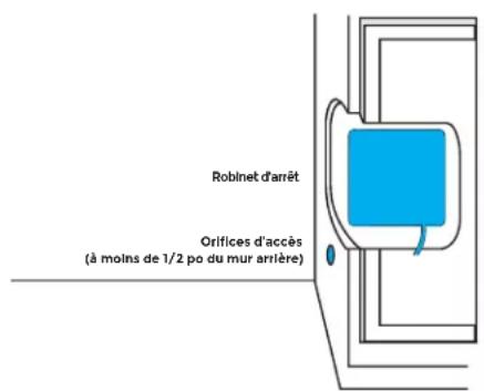
- Bend the copper or PEX tubing to meet the water line inlet, which is located on the back of the refrigerator cabinet. Leave a coil of copper or PEX tubing to allow the refrigerator to be pulled out of the cabinet or away from the wall for service.
Connect to Refrigerator
- Unplug refrigerator or disconnect power.
- Remove and discard the short, black plastic part from the end of the water line inlet.
- Thread the nut onto the end of the tubing. Tighten the nut by hand. Then tighten it with a wrench two more turns. Do not overtighten.
NOTE: To avoid rattling, be sure the copper tubing does not touch the cabinet's side wall or other parts inside the cabinet.
natural_image
Pure technical line drawing of a mechanical component with no text or symbols-
Install the water supply tube clamp around the water supply line to reduce strain on the coupling.
-
Turn shutoff valve on.
-
Check for leaks. Tighten any connections (including connections at the valve) or nuts that leak.
On some models, the ice maker is equipped with a built-in water strainer. If your water conditions require a second water strainer, install in the 1/4" (6.35 mm) water line at either tube connection. Obtain a water strainer from your appliance dealer.
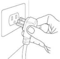
Plug in Refrigerator
WARNING

Electrical Shock Hazard
Plug into a grounded 3 prong outlet.
Do not remove ground prong.
Do not use an adapter.
Do not use an extension cord.
Failure to follow these instructions can result in death, fire, or electrical shock.
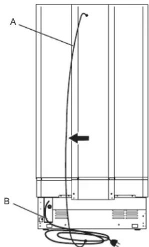
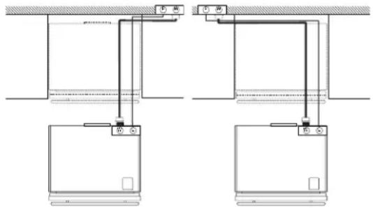
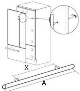
A. Bungee
B. Power Cord
A. Bungee B. Power Cord
- One end of the bungee is connected to the power supply cable by means of a clamp.
- During assembly the power supply cable and its bungee are clamped and housed in the lower left.
- During installation, remove the cable and its bungee from the housing.
- Connect the free end of the bungee to the top screw of the body.
-
The electrical cable can now be supported avoiding getting caught on the wheels, avoiding pulling the electrical cable damaging it and facilitating the installation of the equipment in the recessed niche and enclosure.
-
Plug into a grounded 3-prong outlet. NOTE: Allow 24 hours to produce the first batch of ice. Discard the first three batches of ice produced. Allow 3 days to completely fill the ice storage bin.
natural_image
Line drawing of a hand inserting a plug into an electrical outlet (no text or symbols)- Flush the water system. See "Water and Ice Dispensers."
Move Refrigerator To Final Location
WARNING
Tip Over Hazard
Refrigerator is top heavy and tips easily when not completely installed.
Keep doors taped closed until refrigerator is completely installed.
Use two or more people to move and install refrigerator.
Failure to do so can result in death or serious injury.
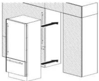
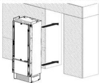
Built-in Installation Single Refrigerator
For a built-in installation, special side profiles are installed between refrigerator and adjacent cabinets.
For installation follow the steps:
There are 2" x 2" x 1/4" spacers (x10) secured to the refrigerator with 2 screws that need to be left on the unit at each location intended for the 'Profile Connection Trim' (x10) pieces. Remove the screw from each spacer (x10) closest to the front of the refrigerator and use those screws to attach the (x10) 'Profile Connection Trim' pieces to the 'Appliance. DO NOT OVERTIGHTEN.
Side Profiles Mounting:
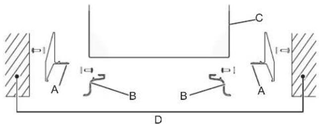
A. Profile Connection Trim
B. Profile Trim Cover
C. Appliance
D. Wall of Furniture
■ Place the refrigerator into the installation structure.
natural_image
Architectural line drawing of a building facade with vertical structural elements (no text or symbols)Use the (x10) screws supplied in the installation packet, to go through the Profile Connection Trim (x10) pieces attached to the refrigerator, to secure the refrigerator to the (D) 'Wall of Furniture'.
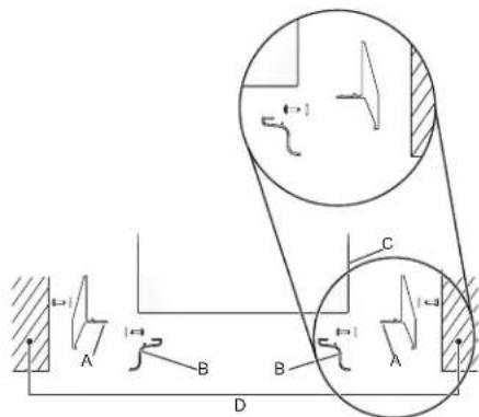
A. Profile Connection Trim
B. Profile Trim Cover
C. Appliance
D. Wall of Furniture
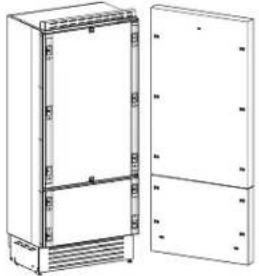
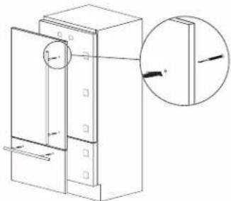
Refrigerator Doors Panel Mounting
Attaching Door Panels
natural_image
Technical line drawing of a cabinet with open door and side panels (no text or symbols)Holes positions:
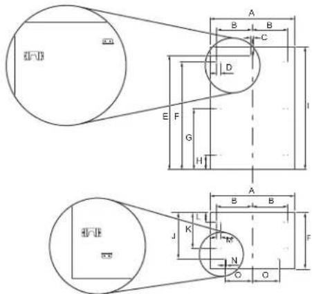
A. 29 78 " (759 mm)
- 54 316 " (1377 mm)
B. 13 7/16" (342 mm)
J. 50" (507.5 mm)
C. 1/4" (6.5 mm)
K. 15 116 " (382 mm)
D. 15116 " (34 mm)
L. 3 ^15/_16 " (100 mm)
E. 50" (1270 mm)
M. 1^5/_16'' (34 mm)
F. 45 11/16" (1160 mm)
N. 1/2" (13 mm)
G. 25 7/8" (657 mm)
O. 11" (279.5 mm)
H. 6 ^1/16 " (154 mm)
P. 253/8" (645 mm)
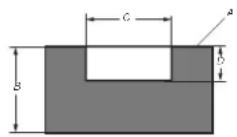
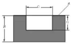
Panels Dimensions Single Bottom - Drawer
Panels can have thickness ranging between 3/4" (18 mm) and 11/8" (28 mm).
Door panels can have a maximum weight 19 kg (42 lbs) and drawer panels may be a maximum weight of 9 kg (20 lbs).
Exceeding these weights could void your warranty for any service issues which can be attributed to overweight panels.
The hinging mechanism on refrigerator is considered to be 'Zero-clearance'. The door and drawer widths specified below assume the minimum niche width is being used and a 1/8" (3.5 mm) reveal is desired around the panels. Adjust your panel dimensions accordingly to your own design criteria considering your niche width and your reveal. Minimum distance should not be less than 1/16" (1.5 mm).
A. 29 78 " (759 mm)
D. 25 ^3/_8 " (645 mm)
B. 54 ^3/_16 " (1377 mm)
E. 84" (2134 mm)
C. 1/4" (6 mm)
Door panel:
Width: 29/8" (759 mm)
Height: 54 ^3 / _16 " (1377 mm)
Drawer panel:
Width: 29 ^7 /8" (759 mm)
Height: 25 ^3 / _8 " (645 mm)
If you want a 6" toe kick height then your bottom drawer panel height would be 22".
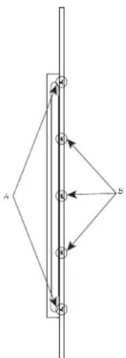
Panel Mounting
Preparation of Door Panels
A. 30" (762 mm)
natural_image
Pure mechanical cross-section diagram without any text, numbers, or symbols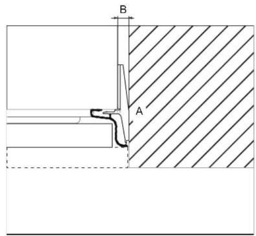
A. Lateral Connection Kit B. 1/2" (13 mm)
The dimensions of the panels are indicated in the table and drawings on below pages.
According to the requirements for aligning with other kitchen structures, the door panel can be higher than the upper edge of the refrigerator door, and the drawer panel can be lower than the edge of the drawer.
The panels must be mounted using special brackets which attach to adjustable devices provided on the door and drawer and with brackets that anchor and adjust the panel's vertical direction.
Brackets and fixing screws are provided with the refrigerator and must be applied to the panel as indicated.
Follow the instructions:
To prepare the panels to be mounted on the refrigerator, follow these steps, working on the back of the panel.
Door Panel
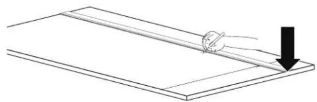
■ Draw a vertical center line on the panel from top to bottom.
■ Starting from the bottom edge of the panel, mark the position of the brackets.
natural_image
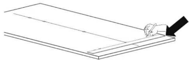
Simple line drawing of a hand holding a tool over a flat surface, with a downward arrow indicating motion (no text or symbols)■ Mark the external and then the internal hole.
natural_image
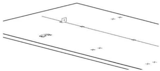
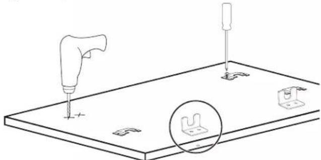
Line drawing of a hand using a tool to cut or mark a rectangular object on a flat surface (no text or symbols)■ Position the brackets on each set of marks to make sure they are aligned, if you choose to drill small pilot holes for the screws pay special attention to not pass through the panel entirely.
natural_image
Pure geometric diagram with lines and symbols, no text or labels present■ Screw the brackets in place.
natural_image
Simple line drawing of a rectangular board with a hand holding a pen, no text or symbols present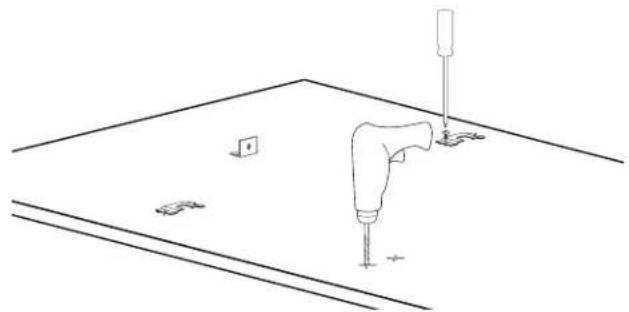
natural_image
Line drawing of a mechanical assembly with a tool and mounting base (no text or symbols)Drawer Panel
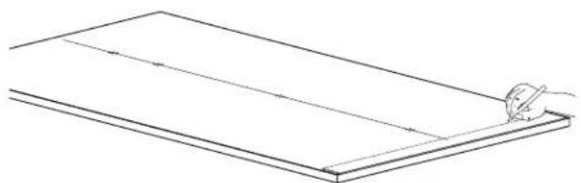
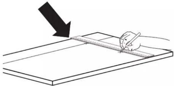
■ When preparing the Drawer Panel, follow the same instructions as per the door panel, but make sure measurements are taken starting from the top edge.
natural_image
Simple line drawing of a hand holding a pen over a flat surface, with a downward arrow indicating the direction (no text or symbols)The height-adjustment support brackets are oriented the opposite way.
natural_image
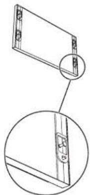
Technical line drawing of a mechanical assembly with a tool and base plate, showing no text or symbols.■ Prepare the refrigerator door (and drawer(s) if applicable) for panel mounting by threading the shoulder bolts into the recessed receivers and the set screws into the other hole. Ensure the end with the hex key socket is threaded into the door and not on the visible end. Thread this in far enough that it is flush with refrigerator door face so as not to interference with hanging the panel. You will adjust these later from the inside of the door and drawer.
natural_image
Technical line drawing of a mechanical component with two views (top and side), no text or symbols present.†TORX and T30 are trademarks of Acument Intellectual Properties, LLC. *Numbers may vary depending on refrigerator model and handle type.
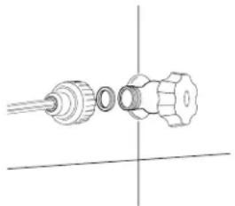
Attaching Door Handles
NOTE: Handles will have to be mounted on the panels before they are applied to the refrigerator.
Follow the instructions:
■ Drill two holes on the back of the panels.
■ Depending on the style of panel, it may be necessary to create tapered countersinks for the screw heads.
natural_image
Technical line drawing of a mechanical device with a magnified inset showing a detail (no text or symbols)NOIR™ Style Door Handle
BEFORE YOU BEGIN: The handle and handle mounting hardware must be installed before installing the custom wood panel. A qualified cabinet maker must perform the installation.
IMPORTANT:
■ This kit is designed to be used only with custom wood panels with thickness of 3/4" (18 mm) 12 "1(28 mm).
■ To avoid handle damage, lift the door and drawer panel(s) by the edges.
TOOLS NEEDED: Gather the required tools and parts before starting installation. Read and follow the instructions provided with any tools listed here.
■ Tape measure
■ 3/4" forstner bit
■ Pencil
■ Torx T30 ^+ bit
■ Cordless drill
■ 11/32" socket driver
■ 1/4" Drill bit
■ Torque Wrench
■ 11/32" Drill bit
PARTS SUPPLIED WITH HANDLE:
■ Handle - freezer drawer
■ Handle - refrigerator door*
■ Screws - 1/4-20 x 0.791"
■ Hex nuts - #8-32 x 0.124"
Install the Refrigerator Handle(s)
IMPORTANT:
■ Verify panel dimensions before drilling any holes.
■ For hole locations and the spacing requirements of NOIR™ handle mounting, refer Figure 1.
NOTE: Figure 1 represents a Side by Side (left) freezer panel, a French door (left) refrigerator panel, a bottom mount left swing refrigerator panel, and column refrigerator/freezer panel. Mirror the hole pattern on the opposite door panel as required.
- Mark the hole locations as shown in Figure 1.
- Clearance is required for the handle fasteners on the back side of the panel. Flip the panel over to reveal the backside of the panel. Using a 3/4" forstner bit, drill a 9/32" (7 mm) deep counterbore at the top and bottom hole locations as shown in Figure 2 - Detail X.
-
Drill a 5/16" (8.2 mm) holes at the top and bottom locations shown in Figure 2 - Detail X.
-
Using a 3/4" forstner bit, drill a 7/16" (11.2 mm) deep counterbore at the middle three locations shown in Figure 2 - Detail Y.
- Drill a 1/4" (6.2 mm) hole at the middle three locations as shown in Figure 2 - Detail Y.
NOTE: Confirm hole depth by temporarily placing fastener into the hole. - Place the handle on the front of the panel. Using Torx T30 screwdriver, secure the handle to panel by tightening the two 1/4" screws on handle ends. Recommended screw torque is 28 lb-in. Fasten three #8-32 nuts to the middle three locations. Nuts should be snug.
NOTE: Do not overtighten. Do not use impact driver. - If you have two refrigerator doors or a side-by-side doors, repeat steps 1 through 6 to install the other handle.
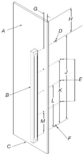
Figure 1 - Refrigerator/freezer door
A. Door panel
G. 1^13/_16'' (46 mm)
B. NOIR™ handle
H. 5 ^5/8 " (142 mm)
C. Bottom surface of door panel
- 38 18 " (968 mm)
D. 1/4-20 X 0.791" Screw (1)
J. 28 5/18'' (726 mm)
E. #8-32 X 0.124" Hex nut (3)
K. 19" (241 mm)
F. 1/4-20 X 0.791" screw (1)
L. 9^1/2 " (241 mm)
flowchart
graph TD
    A["A"] --> B["B"]
    B --> C["C"]
    C --> A
    style A fill:#f9f,stroke:#333
    style B fill:#ccf,stroke:#333
    style C fill:#cfc,stroke:#333
Figure 2 - Cross sectional view
A. 2X refer detail 'X' B. 3X refer detail 'Y'
Detail 'X'
Step '2' Step '3'
A. Backside of panel
A. 5/16" (8.3 mm)
B. 3/4" (19.05 mm)
B. 3/4" (19.05 mm)
C. 3/4" (19.05 mm)
C. 3/4" (19.05 mm)
D. 1/4" (7 mm)
D. 1/4" (7 mm)
Detail 'Y'
Step '4' Step '5'
A. Backside of panel
A. 1/4" (6.2 mm)
B. 3/4" (19.05 mm)
B. 3/4" (19.05 mm)
C. 3/4" (19.05 mm)
C. 3/4" (19.05 mm)
D. 7/16" (11.2 mm)
D. 7/16" (11.2 mm)
Install the Freezer Drawer Handle
IMPORTANT:
■ Verify panel dimensions before drilling any holes.
■ Verify before drilling that the hole pattern is at center.
-
Clearance is required for the handle fasteners on the backside of the panel. Flip the panel over to reveal the backside of the panel. Using a 3/4" forstner bit, drill a 9/32" (7 mm) deep counterbore at the left and right hole locations as shown in Figure 4 - Detail X.
-
Drill a 5/16" (8.2 mm) hole at the left and right locations as shown in Figure 4 - Detail X.
- Using a 3/4" forstner bit, drill a 7/16" (11.2 mm) deep counterbore at the middle three locations as shown in Figure 4 - Detail Y.
- Drill a 1/4" (6.2 mm) hole at the middle three locations as shown in Figure 4 - Detail Y.
NOTE: Confirm hole depth by temporarily placing fastener into the hole.
- Place the handle on the front of the panel. Using Torx T30 screwdriver, secure the handle to panel by tightening the two 1/4" screws on the handle ends. Recommended screw torque is 28 lb/in. Fasten three #8-32 nuts to the middle three locations. Nuts should be snug.
NOTE: Do not overtighten. Do not use impact driver.
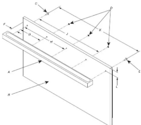
Figure 3 - Freezer drawer
A. NOIR handle
G. 7 ^11/16 " (170 mm)
B. Door panel
H. 13 ^3/8 (340 mm)
C. 1/4-20 X 0.791" Screw (1)
- 20 18 " (511 mm)
D. #8-32 X 0.124" Hex nut (3)
J. 26 ^16 / _16 " (681 mm)
E. 1/4-20 X 0.791" Screw (1)
K. 2" (51 mm)
F. 1^5/_8'' (41 mm)
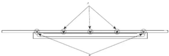
Figure 4 - Cross sectional view
A. 3X refer detail 'Y' B. 2X refer detail 'X'
Detail 'X'
Step '2' Step '3'
A. Backside of panel
A. 3/4" (19.05 mm)
B. 3/4" (19.05 mm)
B. 3/4" (19.05 mm)
C. 3/4" (19.05 mm)
C. 5/16" (8.3 mm)
D. 1/4" (7 mm)
D. 1/4" (7 mm)
Detail 'Y'
Step '4' Step '5'
A. Backside of panel
A. 3/4" (19.05 mm)
B. 3/4" (19.05 mm)
B. 3/4" (19.05 mm)
C. 3/4" (19.05 mm)
C. 1/4" (6.2 mm)
D. 7/16" (11.2 mm)
D. 7/16" (11.2 mm)
†TORX and T30 are trademarks of Acument Intellectual Properties, LLC.
*Numbers may vary depending on refrigerator model and handle type.
RISE™ Style Door Handle
BEFORE YOU BEGIN: The handle and handle mounting hardware must be installed before installing the custom wood panel. A qualified cabinet maker must perform the installation.
IMPORTANT:
■ This kit is designed to be used only with custom wood panels with thickness of 3/4" (18 mm) 1/2" 1(28 mm).
■ To avoid handle damage, lift the door and drawer panel(s) by the edges.
TOOLS NEEDED: Gather the required tools and parts before starting installation. Read and follow the instructions provided with any tools listed here.
■ Tape measure
■ 3/4" forstner bit
■ Pencil
■ Torx T30 ^+ bit
■ Cordless drill
■ 11/32" socket driver
■ 1/4" Drill bit
■ Torque Wrench
■ 11/32" Drill bit
PARTS SUPPLIED WITH HANDLE:
■ Handle - freezer drawer
■ Handle - refrigerator
■ Screws - 1/4-20 x 1.5"
door*
Install the Refrigerator Handle(s)
IMPORTANT:
■ Verify panel dimensions before drilling any holes.
■ For hole locations and the spacing requirements of RISE™ handle mounting, refer Figure 1.
NOTE: Figure 5 represents a Side by Side (left) freezer panel, a French door (left) refrigerator panel, a bottom mount left swing refrigerator panel, and column refrigerator/freezer panel. Mirror the hole pattern on the opposite door panel as required.
- Clearance is required for the handle fasteners on the backside of the panel. Flip the panel over to reveal the backside of the panel. Using a 3/4" forstner bit, drill a 1/4" (7 mm) deep counterbore at the top and bottom hole locations as shown in Figure 6 - Detail X.
- Drill a 5/16" (8.3 mm) hole at the top and bottom locations shown in Figure 6 - Detail X.
NOTE: Confirm hole depth by temporarily placing fastener into the hole.
- Place the handle on the front of the panel. Using Torx T30 screwdriver, secure the handle to panel by tightening the two 1/4" screws on handle ends. Recommended screw torque is 28 lb/in.
NOTE: Do not overtighten. Do not use impact driver.
- If you have two refrigerator doors or a side-by-side doors, repeat steps 1 through 3 to install the other handle.
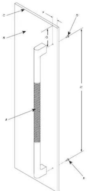
Figure 5 - Refrigerator/freezer door
A. RISE™ handle
E. 1/4-20 X 1.5" Screw (1)
B. Door panel
F. 1^13/_16'' (46 mm)
C. Top surface of door panel
G. 5^11/_16 " (144 mm)
D. 1/4-20 X 1.5" Screw (1)
H. 37 7/8" (963 mm)
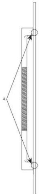
Figure 6 - Cross sectional view
A. 2X refer detail 'X'
Detail 'X'
Step '2' Step '3'
A. Backside of panel
A. 3/4" (19.05 mm)
B. 3/4" (19.05 mm)
B. 5/16" (8.3 mm)
C. 3/4" (19.05 mm)
C. 3/4" (19.05 mm)
D. 1/4" (7 mm)
D. 1/4" (7 mm)
Install the Freezer Drawer Handle IMPORTANT:
■ Verify panel dimensions before drilling any holes.
■ Verify before drilling that the hole pattern is at center.
- Clearance is required for the handle fasteners on the backside of the panel. Flip the panel over to reveal the backside of the panel. Using a 3/4" forstner bit, drill a 1/4" (7 mm) deep counterbore at the left and right hole locations as shown in Figure 8 - Detail X.
- Drill a 5/16" (8.3 mm) hole at the left and right locations as shown in Figure 8 - Detail X.
- Place the handle on the front of the panel. Using Torx T30 screwdriver, secure the handle to panel by tightening the two 1/4" screws on the handle ends. Recommended screw torque is 28 lb/in.
NOTE: Do not overtighten. Do not use impact driver.
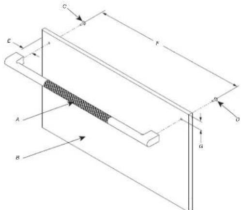
Figure 7 - Freezer drawer
A. RISE™ handle
E. 1 ^11/16 " (43 mm)
B. Drawer panel
F. 26 58 " (676 mm)
C. 1/4-20 X 1.5" Screw (1)
G. 2" (51 mm)
D. 1/4-20 X 1.5" Screw (1)
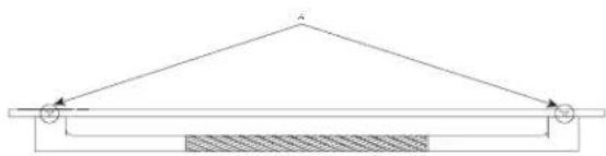
Figure 8 - Cross sectional view
A. 2X refer detail 'X'
Detail 'X'
Step '2' Step '3'
A. Backside of panel
A. 3/4" (19.05 mm)
B. 3/4" (19.05 mm)
B. 3/4" (19.05 mm)
C. 3/4" (19.05 mm)
C. 1/4" (7 mm)
D. 1/4" (7 mm)
D. 5/16" (8.3 mm)
■ Place the handle on top of the holes and insert the screws through the washer, the panel, the standoff and into the threaded receivers in the handle.
■ Place firmly but do not over tighten as damage may occur to the handle or the panel.
Install Door & Drawer Handles
Follow the below steps to install handles on doors and drawers:
■ Insert the handle ends onto the supports already installed on the door and the drawer.
■ Tighten the Allen screws available on the handle.
IMPORTANT: The screws must be tightened by 1/8" (2.5 mm) hex key or bit.
Attaching Door Panels and Bottom Drawer
NOTE: Once all brackets and handles are attached to the panels, you can start installation of the bottom drawer.
Follow the instructions:
■ Do not tighten fully tighten the screw to the receiver.
natural_image
Diagram of a door hinge mechanism with arrows indicating movement or force (no text or symbols)■ Put the bottom drawer panel starting from the adjustment bolts on the bottom.
natural_image
Diagram showing two rectangular panels with directional arrows indicating rotation or movement, no text or symbols present.It is now possible to align panels to adjacent cabinets in height using the lower alignment bolts and brackets, tightening or untightening the screws into position as needed. With the screw not fully tightened, move the panel sideways manually to align it to the other panels on the unit or other adjacent structures.
Set the bottom adjustment bolts using the lock nut once you are happy with the height alignment.
natural_image
Pure mechanical diagram showing a lever and curved pipe with directional arrows (no text or symbols)■ Depth alignment: working from the inside of the drawer, after lifting up the magnetic seal or rotating the cover plate where necessary, adjust the panel position in the Z-direction by adjusting the shoulder bolts and setscrews with the 4 mm hex key in conjunction with each other finally locking each mounting position in place.
A. Adjustment Reglage
B. Lock Blocage
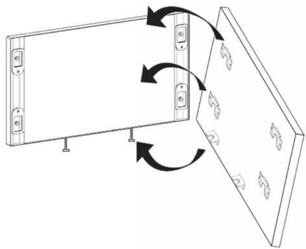
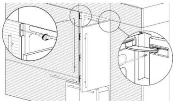
■ Attach the panel to the fixing devices starting from the top aligning brackets.
natural_image
Technical line drawing of a refrigerator with an inset close-up showing internal components (no text or symbols)At this point, alignment between the panel and adjacent cabinets can be adjusted using the alignment brackets and small brackets.
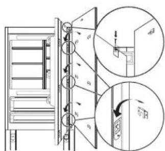
■ Vertical alignment: tighten or loosen the screw in the brackets to raise or lower the panel.
natural_image
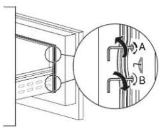
Technical diagram of a mechanical assembly with directional arrows indicating motion (no text or symbols)■ Depth alignment: working from the inside of the door, after lifting up the magnetic seal on the handle side and rotating the plastic covers on the hinge side, adjust the panel position in the Z-direction by adjusting the shoulder bolts and setscrews with the 4 mm hex key in conjunction with each other finally locking each mounting position in place.
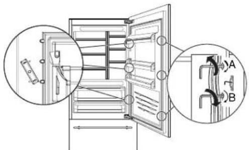
A. Adjustment Reglage
B. Lock Blocage
NOTE: Once the front panel has been adjusted, check that the gasket has been repositioned correctly to assure the door/ drawer are closing correctly and avoid operational errors of the unit.
■ To ensure proper ventilation for your refrigerator, allow for 5 mm of space behind the refrigerator to prevent overheating.
■ To avoid floor damage, make sure levelers are raised (not touching floor) and refrigerator is on rollers before moving.
■ Attach anti-tip brackets (see page 8).
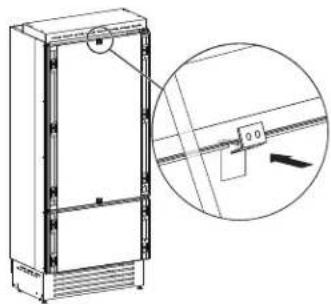
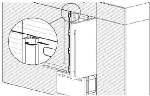
■ Attach upper grill mounting brackets and upper grille.
natural_image
Technical line drawing of a mechanical assembly with two circular insets showing close-ups of components (no text or symbols)■ Insert one edge of each (B) 'Profile Trim Cover' into each of the (A) 'Profile Connection Trim' pieces and push firmly until a 'click' is heard. See image on top left of page 13.
natural_image
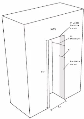
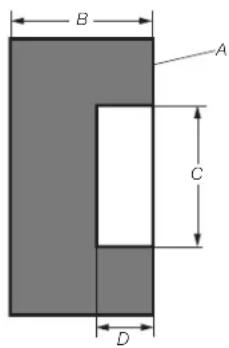
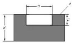
Technical line drawing of a mechanical assembly with a magnified inset showing internal components (no text or symbols)Maximum cabinet depth over "Integrated" refrigerator with single door panel
It is possible to design a panel which will be the same for the structure where refrigerator is going to be place and the cabinet on the top of the same structure.
In this case, the total depth of the cabinet without the door (above the refrigerator) must not exceed the total depth of the refrigerator itself.
A. 1 7/8" (47 mm) + front panel thickness
B. 23" (585 mm)
C. 25 58 " (650 mm)
This will allow the panel attached to the refrigerator door to open correctly without interference during its rotation up to 105°.
Leveling
WARNING
Excessive Weight Hazard
Use two or more people to move and install or un appliance.
Failure to do so can result in back or other injury.
IMPORTANT: All four leveling legs must contact the floor to support and stabilize the full weight of refrigerator. Rollers are moving the refrigerator, not for permanent support.
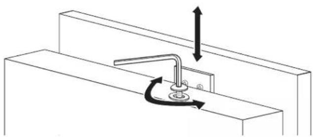
After moving the refrigerator to its final location:
- Use a 11/16" (17 mm) socket driver to turn the leveling bolts clockwise or counterclockwise to adjust the legs to the floor as shown. The rollers should be off the floor.
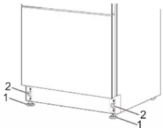
natural_image
Technical line drawing of a 3D rectangular frame with labeled components (no text or symbols present)- Adjust the leveling legs to level and align the refrigerator from left to right and front to back so that the refrigerator is level and aligned with the cabinets.
- Continue adjusting the leveling legs until the top of the refrigerator is making contact with the bottom of the solid soffit, or the bottom of the anti-tip boards, if anti-tip boards were used. Do not crush the compressor cover.
IMPORTANT: Adjust in small increments to keep from damaging the cabinet trim and causing problems with the door alignment or top grille fit.
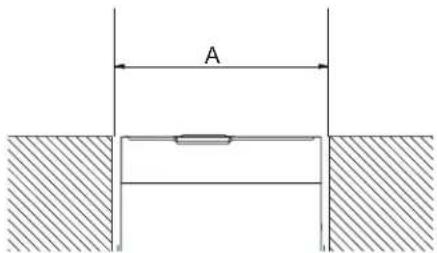
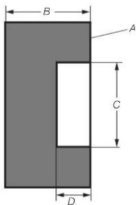
Install Base Grille
Grille assures ventilation which is placed in front lower portion of the refrigerator.
If kickplate is present, then it must be designed to maintain satisfactory air flow, as described in below drawing.
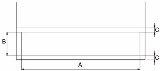
nsta
| A | 27^15/_16" (710 mm) |
| B | >4" (100 mm) |
| C | 3/8" (10 mm) |
Total area is half of the kickplate area, so holes can be of any size for and shape.
For better air flow, advised to remove front grille of the refrigerator.
Grille is attached with refrigerator by means of magnetic plates which will help in removal and regular cleaning operations for customer.
NOTE: Air inlet and outlet must not be blocked and condenser must be cleaned on regular basis.
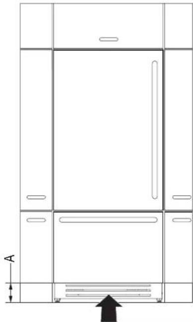
natural_image
Line drawing of a double door cabinet with an arrow indicating upward motion (no text or symbols)A. 4" (100 mm)
Complete Installation
- Remove the label after the installation is done.
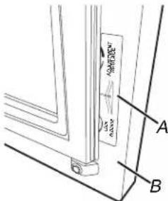
A.Label
B. Door
- Turn the water supply line valve to the "Open" position.
- Turn the refrigerator switch to the ON position. See "Power On/ Off Switch" in the Use & Care Guide for instructions. Wait a few minutes. Check the water line connections for leaks.
- Remove all boxes, parts packages and packing materials from the interior of the refrigerator. See the "Cleaning" section in the Use & Care Guide for instructions. Remove the film and cardboard from the grille and doors or door frame, depending on your model.
- Install the shelves and bins in the refrigerator and freezer compartments.
- The controls are preset at the factory to the midpoint setting. Check that the compressor is operating properly and that all the lights are working.
- Flush the water system before use. See "Water System Preparation."
REFRIGERATOR FEATURES
Operating Your Refrigerator
How to use the refrigerator with electronic control
Your refrigerator is equipped with a cutting-edge and user-friendly electronic temperature control located on the front panel of the refrigerator door.

Date
The display will show the date in the format (day:month:year).
By touching the display you can modify the settings.

Time
The display shows the hours and minutes in the format hh:mm.
This function selects the display at 12 hours or 24 hours.
Celsius or Fahrenheit degrees
This function permits visualizing the temperature in Centigrade or Fahrenheit degrees. Normally, the refrigerator is set for visualization in centigrade degrees.

Language
To set the language of the refrigerator, simply touch the settings button on the display.

Reset
It gives the possibility to restore the base settings that were set in the factory, cancelling all the changes that has been made from there onward.

Demo Mode
It is possible to simulate the functioning of the refrigerator, for showroom display or for fairs.
Demo Mode function works when the compartments are at the set temperatures.

Maintenance
Units requires, for a correct operation, the cleaning of the ventilation grille, of the filter and the condenser. The default setting of the unit is "Warning disabled".

Service
The service function is reserved for the assistance.

Info System
The function Info System shows the data of the products for example the software's code, serial number and the factory's codes of the refrigerator.
Water and Ice Dispensers
Follow the instructions for the hygienic safety of the water dispensed.
- When using the refrigerator for the first time and every time the filter is changed, it is recommended to let the water flow in the circuit using the "Manual Cleaning" and discard the ice produced in the first 24 hours.
If the water dispenser has not been used for more than 4–5 days, it is advisable to clean the circuit and run off the first liter of water.
■ Reposition the removable water dispenser (if present), ensuring your hands are hygienically clean.
■ Clean the ice drawer regularly by using only drinking water.
■ The filter must be changed when indicated on the control panel or when the ice/water dispenser has not been used for more than 30 days.
■ With each filter replacement, sanitize the ice and water distribution system using a food grade disinfectant (with sodium hypochlorite), which does not change the characteristics of the materials. Rinse with at least 2 liters of water before use.
■ Only original spare parts supplied by the manufacturer should be used when replacing components in the ice and water dispenser.
■ Any work on the refrigerator must be carried out by a qualified technician or the After-sales Service.
■ Clean water tanks if they have not been used for 48 hours; flush the water system connected to a water supply if water has not been drawn for 5 days.
If the refrigerator is left empty for long periods, switch off, defrost, clean, dry, and leave the door open to prevent mould developing within the appliance.
Ice Maker

NOTE:
If the ice is not used frequently is advisable to empty the ice bin once every 8-10 days. It is normal that some ice cubes stick to one another. If the ice is not frequently used, the older cubes can become opaque, and will have a strange flavour and become smaller.
■ The Ice maker automatically deactivates if the Vacation function is activated. When the Ice maker is started for the first time, it is recommended to dispose of the first full bin of ice.
■ If the equipment has been switched off for a month or more, it is recommended to perform a water and filter cleaning cycle.
IMPORTANT: The ice maker will continue to operate even when the ice bin is not in position.
■ To activate the Ice Maker after installation of the appliance touch the function icon and then and then the ice maker icon from the functions.
- Allow 24 hours to produce the first batch of ice.
■ The production is of 10 cubes per cycle and approximately 10 cycles in 24 hours.
■ Output depends on the temperature set in the freezer, the room temperature and the frequency of door opening.
■ If the refrigerator is operating without being connected to the water system, make sure that the Ice maker is deactivated.
■ The Ice Maker produces ice until the ice tray is full and will automatically stop once the maximum level is reached.
■ With the SuperIce function, it is possible to increase the quantity of ice produced a 24 hours, while the Set Cube Size function permits selection of the size of the produced ice cubes.
■ The ice cube container should be cleaned occasionally with warm water to prevent the odor. Make sure that you switch off the ice maker before clearing the container. Rinse out and wipe dry.
- Check the contents of the freezer for spoiled or out-of-date food. All odorous foods should be wrapped thoroughly or stored in airtight containers to prevent the build-up of odors.
Operating noises
■ Grumbling: refrigerator is running. Fan in the recirculating air system is running.
■ Bubbling, humming or gurgling noises: refrigerant is flowing through the tubes.
- Clicking: motor is switching on or off. Solenoid valve on the water connection is opening/closing.
■ Rumbling: ice cubes are falling into the ice cube container.
IMPORTANT: Do not place any bottles or food for rapid cooling in the ice cube container. The ice maker may become blocked and be damaged.
natural_image
Line drawing of a refrigerator with open doors and shelves (no text or symbols)ENTRETIEN ET RÉPARATION jeter
Nettoyage
AVERTISSEMENT
Risque d'explosion
natural_image
Pure technical diagram showing mechanical components with arrows indicating motion (no text or symbols)natural_image
Hand inserting a pipe into a wall-mounted sink (no text or symbols visible)natural_image
Simple line drawing of a person lying in bed, no text or symbols presentnatural_image
Line drawing of a hand holding a tray with a handle, no text or symbols presentnatural_image
Line drawing of a mechanical assembly with no visible text, numbers, or symbolsnatural_image
Line drawing of a hand holding a document with a curved arrow indicating rotation (no text or symbols)natural_image
Diagram showing a mechanical lever mechanism with rotational motion arrows (no text or symbols)natural_image
Line drawing of a hand holding a document with an arrow pointing to it (no text or symbols present)Balconnets de porte
natural_image
Technical line drawing of a structural bracket with directional arrows indicating movement (no text or symbols)A. 84 po (2134 mm)
B. 81 14 po (2064 mm)
C. 29 7/16 po (748 mm)
D. 29 1/2 po (749 mm)
E. 29 ^15/_16 po (761 mm)
F. 19 ^11/_16 po (500 mm)
G. 4 1/6po (103 mm)
H. 25 ^3/_8 po (645 mm)
- 1/4 po (6 mm)
J. 54 3/16 po (1377 mm)
K. 24 po (610 mm)
L. 24 ^3/4 po (628 mm)
M. 1/8 po (3 mm)
natural_image
Technical diagram of a mechanical assembly with an inset showing a close-up view of a component labeled 'A' (no text or symbols present)A. butée de porte
Préparation du site
Brides antibasculement
AVERTISSEMENT
A. Brides antibasculement
B. Brides du haut
C. 20 ^15/_16 po (531 mm)
D. 112po (38 mm)
E. 13/16 po (20 mm)
natural_image
Technical line drawing of a cabinet or enclosure assembly with internal components and structural beams (no text or symbols)natural_image
Technical line drawing of a mechanical component with threaded ends and a central hub (no text or symbols)natural_image
Line drawing of hands inserting a plug into an electrical outlet (no text or symbols)natural_image
Technical line drawing of a mechanical assembly with no visible text or symbolsnatural_image
Technical line drawing of a two-door refrigerator with open doors and ventilation grilles (no text or symbols)A. 29 7/8 po (759 mm) I. 54 3/16 po (1377 mm)
B. 13 716 po (342 mm) J. 50 po (507,5 mm)
C. 1/4 po (6.5 mm) K. 15 1/16 po (382 mm)
D. 15 / 16 po (34 mm) L. 3^15 / 16 po (100 mm)
E. 50 po (1270 mm) M. 1^5/16 po (34 mm)
F. 45^11/_16 po (1160 mm) N. 1/2 po (13 mm)
G. 25 7/8 po (657 mm) O. 11 po (279,5 mm)
H. 6 1/16 po (154 mm) P. 25 3/8 po (645 mm)
natural_image
Pure mechanical cross-section diagram without any text, numbers, or symbols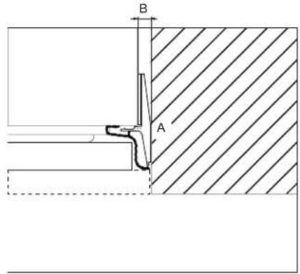
natural_image
Simple line drawing of a ruler measuring a rectangular object (no text or symbols)natural_image
Simple line drawing of a hand holding a tool over a flat surface, with a downward arrow indicating direction (no text or symbols)natural_image
Simple line drawing of a hand holding a pen over a flat surface, with no text or symbols present.natural_image
Pure geometric lines forming a parallelogram with no text, numbers, or symbolsnatural_image
Simple line drawing of a tool on a flat surface with no text or symbolsPanneau de tiroir
natural_image
Simple line drawing of a hand holding a pen on a flat surface, with a downward arrow indicating compression or damage (no text or symbols)natural_image
Technical line drawing of a mechanical assembly with a tool and base plate, showing no text or symbols.natural_image
Technical line drawing of a mechanical bracket assembly with two views (top and side), no text or symbols present.natural_image
Technical line drawing of a mechanical component with a magnified inset showing a detail (no text or symbols)natural_image
Pure mechanical diagram showing a vertical rod with internal components and directional arrows, no text or symbols present.natural_image
Diagram of a door handle assembly with arrows indicating movement or force (no text or symbols)natural_image
Diagram showing two rectangular panels with mounting hardware and directional arrows indicating rotation or movement (no text or symbols)natural_image
Pure mechanical diagram showing a lever and curved pipe without any text, numbers, or symbolsA. Adjustment Réglage
B. Lock Blocage
natural_image
Technical line drawing of a refrigerator with an inset showing a close-up of the panel (no text or symbols present)natural_image
Technical diagram of a mechanical assembly with directional arrows indicating motion (no text or symbols)A. Adjustment Réglage
B. Lock Blocage
natural_image
Technical line drawing of a mechanical assembly with two circular insets showing close-ups of components (no text or symbols)natural_image
Technical line drawing of a mechanical assembly with a magnified inset showing internal components (no text or symbols)natural_image
Technical line drawing of a structural frame with two labeled components (1 and 2), no text or symbols present.natural_image
Technical line drawing of a cabinet or enclosure with door, windows, and an arrow indicating upward motion (no text or symbols present)A. 4 po (100 mm)
Achever l'installation


- BOTTOM-MOUNT REFRIGERATOR OWNER'S MANUAL MANUEL D'UTILISATION DU RÉFRIGÉRATEUR AVEC CONGÉLATEUR EN BAS
- Table of Contents/Table des matières
- Your safety and the safety of others are very important.
- DANGER
- WARNING
- IMPORTANT SAFETY INSTRUCTIONS
- SAVE THESE INSTRUCTIONS
- Proper Disposal of Your Old Refrigerator
- MAINTENANCE AND CARE
- Cleaning
- IMPORTANT:
- To Clean Your Refrigerator:
- Condenser Cleaning
- Changing the LED Module
- Water Filtration System
- Water Filter Status Lights
- Reset Water Filter Status
- Replacing the Water Filter
- Vacation and Moving Care
- Vacations
- Moving
- Sabbath Mode Instructions
- CONTROL PANEL
- Refrigerator Drawers and Shelves Remove and Replace Drawers (for safety reason the removal of drawers is possible only with tools)
- Remove Drawers
- Replace Drawers
- Remove and Replace Ice Tray
- To replace ice tray:
- Refrigerator Shelves
- Shelves
- To replace a shelf:
- Door Bins
- INSTALLATION REQUIREMENTS
- Tools and Parts
- Tools Needed:
- Accessories:
- Product Dimensions
- Door Swing Dimensions
- Site Preparation
- Location Requirements
- Explosion Hazard
- Electrical Requirements
- Recommended Grounding Method
- Water Pressure
- Reverse Osmosis Water Supply
- INSTALLATION INSTRUCTIONS
- Opening Dimensions
- Unpack the Refrigerator
- Excessive Weight Hazard
- Remove the Packaging
- When Moving Your Refrigerator:
- Clean Before Using
- Important information to know about glass shelves and covers:
- Main Components
- Connect the Water Supply
- Connect to Water Line
- Connect to Refrigerator
- Plug in Refrigerator
- Move Refrigerator To Final Location
- Built-in Installation Single Refrigerator
- Refrigerator Doors Panel Mounting
- Attaching Door Panels
- Holes positions:
- Panels Dimensions Single Bottom - Drawer
- Door panel:
- Drawer panel:
- Panel Mounting
- Preparation of Door Panels
- Follow the instructions:
- Door Panel
- Drawer Panel
- Attaching Door Handles
- NOIR™ Style Door Handle
- PARTS SUPPLIED WITH HANDLE:
- Install the Refrigerator Handle(s)
- Install the Freezer Drawer Handle
- RISE™ Style Door Handle
- Install the Freezer Drawer Handle IMPORTANT:
- Install Door & Drawer Handles
- Attaching Door Panels and Bottom Drawer
- Maximum cabinet depth over "Integrated" refrigerator with single door panel
- Leveling
- Install Base Grille
- Complete Installation
- REFRIGERATOR FEATURES
- Operating Your Refrigerator
- Water and Ice Dispensers
- Ice Maker
- NOTE:
- Operating noises
- ENTRETIEN ET RÉPARATION jeter
- Nettoyage
- AVERTISSEMENT
- Balconnets de porte
- Préparation du site
- Panneau de tiroir
- Achever l'installation
Brand : JENN-AIR
Model : JBBFR30NMX
Category : Refrigerator