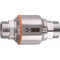
SM2000 - Detector IFM - Free user manual and instructions
Find the device manual for free SM2000 IFM in PDF.


User questions about SM2000 IFM
0 question about this device. Answer the ones you know or ask your own.
Ask a new question about this device
Download the instructions for your Detector in PDF format for free! Find your manual SM2000 - IFM and take your electronic device back in hand. On this page are published all the documents necessary for the use of your device. SM2000 by IFM.
USER MANUAL SM2000 IFM
Operating instructions
Magnetic-inductive flow meter
SM2xxx
SM9xxx
SM0510
Contents
1 Preliminary note.... 4
1.1 Symbols used.... 4
1.2 Warnings.... 4
2 Safety instructions 5
2.1 Cybersecurity 5
3 Transport, handling and storage 6
4 Intended use 7
4.1 Application area 7
4.2 Note regarding SM0510 and SM2130 7
5 Function 8
5.1 Output OUT1 selection options 8
5.2 Output OUT2 selection options 8
5.3 IO-Link 8
6 Mounting 9
6.1 Process connection.... 9
6.2 Interference.... 10
6.3 Installation position.... 10
7 Electrical connection 12
8 Operating and display elements.... 13
9 Menu.... 15
9.1 Main menu and submenus 15
10 Set-up 20
11 Parameter setting 21
11.1 Parameter setting via the unit keys 21
11.2 Parameter setting via IO-Link 21
11.3 Output configuration 22
11.3.1 Switching signal for limit value monitoring.... 22
11.3.2 Analogue signal.... 23
11.3.3 Frequency signal 24
11.3.4 Consumed quantity monitoring (totaliser function) 25
11.3.4.1 Switching signal totaliser 26
11.3.4.2 Pulse signal totaliser 27
11.3.5 Switching signal empty pipe detection 27
11.4 Application configuration 28
11.4.1 Standard unit of measurement 28
11.4.2 Error behaviour of the outputs 28
11.4.3 Start-up delay 29
11.4.4 Output polarity of the switching outputs.... 30
11.4.5 Damping 30
11.4.6 Low flow cut-off 31
11.4.7 Flow direction.... 32
11.4.8 Counting method of the totaliser 32
11.4.9 Totaliser reset 33
11.4.10 Lock / unlock 34
11.4.11 Device reset.... 34
11.5 Display 34
11.5.1 Display standard process value 34
11.5.2 Display update rate and rotation 35
11.5.3 Switch off the display.... 35
11.6 Diagnostics and service functions.... 36
11.6.1 Device information 36
11.6.2 Memory 36
11.6.3 Simulation 37
12 Troubleshooting.... 38
12.1 Warning messages.... 38
12.2 Error messages 38
13 Maintenance, repair and disposal 40
14 Factory setting.... 41
1 Preliminary note
You will find instructions, technical data, approvals and further information using the QR code on the unit / packaging or at documentation.ifm.com.
1.1 Symbols used
√ Requirement
Instruction
Reaction, result
bold Designation of keys, buttons or indications
→ Cross-reference without link
→ Cross-reference with link

Important note
Non-compliance may result in malfunction or interference

Information
Supplementary note
1.2 Warnings
Warnings indicate the possibility of personal injury and damage to property. This enables safe product handling. Warnings are graded as follows:

WARNING
Warning of serious personal injury
▷ If the warning is not observed, fatal and serious injuries are possible.

CAUTION
Warning of minor to moderate personal injury
▷ If the warning is not observed, minor to moderate injuries are possible.

ATTENTION
Warning of damage to property
▷ If the warning is not observed, damage to property is possible.
2 Safety instructions
- The unit described is a subcomponent for integration into a system.
- The system architect is responsible for the safety of the system.
-
The system architect undertakes to perform a risk assessment and to create documentation in accordance with legal and normative requirements to be provided to the operator and user of the system. This documentation must contain all necessary information and safety instructions for the operator, the user and, if applicable, for any service personnel authorised by the architect of the system.
-
Read this document before setting up the product and keep it during the entire service life.
- The product must be suitable for the corresponding applications and environmental conditions without any restrictions.
- Only use the product for its intended purpose (→ Intended use).
- Only use the product for permissible media.
- If the operating instructions or the technical data are not adhered to, personal injury and/or damage to property may occur.
- The manufacturer assumes no liability or warranty for any consequences caused by tampering with the product or incorrect use by the operator.
- Installation, electrical connection, set-up, operation and maintenance of the product must be carried out by qualified personnel authorised by the machine operator.
- Protect units and cables against damage.
2.1 Cybersecurity
Installation
The device is suitable for operation in a secure environment according to IEC 62443-1-1.
The device was designed for operation behind a firewall.
▶ Carry out a risk assessment of the system according to IEC 62443-1-1.
▶ Take measures to ensure physical security.
Operation
▶ Observe the security functions described in the product documentation and the recommendations for their use.
Maintenance
▶ Back up system configuration and system data in accordance with your company's change management processes.
Decommissioning
▶ Ensure that no sensitive information can fall into unauthorised hands.
▶ Always reset the system settings to the factory settings before decommissioning the device.
3 Transport, handling and storage
▶ Store the device in its original packaging.
▶ When the device is to be stored again, use the original packaging.
▶ Otherwise, provide unused connections with either a mating connector or a protective cap and pack the device in suitable packaging.
▶ Observe the permissible ambient conditions for the device during storage (→ Technical data).
4 Intended use
The unit monitors liquid media.
The device detects the process values volume flow (flow quantity/time), the consumed quantity and the medium temperature.
4.1 Application area
Conductive liquids with the following properties:
• Conductivity: ≥ 20 μS/cm
- Viscosity: < 70 mm2 / s at 40° C; < 70 cST at 104° F

This is a class A product. This product may cause radio interference in domestic areas.
▶ If required, take appropriate EMC screening measures.

Pressure Equipment Directive (PED): The units comply with the Pressure Equipment Directive and are designed and manufactured for group 2 fluids in accordance with the sound engineering practice. Use of media from group 1 fluids on request.
4.2 Note regarding SM0510 and SM2130

Operation in overload conditions can cause cavitation. Operation with cavitation can damage the pressure-carrying parts.
▶ Consider the cavitation limits (→ Technical data).
5 Function
- The device detects the volumetric flow on the magnetic-inductive volumetric flow measuring principle.
- As additional process value the unit detects the medium temperature.
- The unit can be operated in SIO mode (standard input-output) or in IO-Link mode.
- The unit displays the current process values.
- The unit generates two output signals according to the parameter setting.
5.1 Output OUT1 selection options
- Switching signal flow
• Frequency signal flow - Switching signal totaliser
- Pulse signal totaliser
- Switching signal empty pipe detection
- IO-Link
5.2 Output OUT2 selection options
- Switching signal flow
- Switching signal temperature
- Analogue signal flow
• Analogue signal temperature - Switching signal empty pipe detection
• Input for external totaliser reset
5.3 IO-Link
IO-Link is a communication system for connecting intelligent sensors and actuators to automation systems. IO-Link is standardised in the IEC 61131-9 standard.

General information on IO-Link at io-link.ifm

Input Output Device Description (IODD) with all parameters, process data and detailed descriptions of the device at documentation.ifm.com
IO-Link offers the following advantages:
• Interference-free transmission of all data and process values
• Parameter setting in the running process or presetting outside the application
- Parameters for identifying the connected devices in the system
• Additional parameters and diagnostic functions
• Automatic backup and restore of parameter sets in case of device replacement (data storage)
- Logging of parameter sets, process values and events
• Device description file (IODD - Input Output Device Description) for easy project planning
• Standardised electrical connection
- Remote maintenance
6 Mounting

CAUTION
If the medium temperature is above 50\ °C ( 122\ °F ), parts of the housing can increase in temperature to over 65\ °C ( 149\ °F ).
▷ Risk of burns.
▶ Protect the housing against contact with flammable substances and unintentional contact.
▶ Apply the supplied warning label to the sensor cable.

ATTENTION
No functional earthing when installed in an ungrounded pipe system (e.g. plastic pipes).
▷ Deficient operating function.
▶ Ground the device. Ground brackets for the M12 connector are available as accessories, see documentation.ifm.com.
▶ Make sure that no pressure is applied to the system.
▶ Ensure that no media can leak at the mounting location during installation.
▶ Avoid deposits, accumulated gas and air in the pipe system.
After installation, air bubbles in the system can affect the measurement. Corrective measures:
▶ Rinse the system after the installation for ventilation. Rinsing quantity > 15 l/min, 4 gpm.
6.1 Process connection
The devices with a G thread can be installed in the pipes using adapters.
Adapters have to be ordered separately as accessories.
• Information about the available mounting accessories at www.ifm.com.
- A correct fit of the device and ingress resistance of the connection are only ensured using ifm adapters.

▶ Observe the instructions of the mounting accessories.

▶ Take the tightening torques for sensor and fixing elements into account.

Fig. 1: Process connection for devices with G-thread
1: Pipe
2: Adapter
3: Sealing
4: G-thread
▶ Grease the threads of the process connection, adapter and sensor. Use a lubricating paste which is suitable and approved for the application.
▶ Screw the adapters into the pipe.
▶ Insert the seals and insert the device according to the marked flow direction.
▶ Screw the adapters to the sensor thread until they are hand-tight.
▶ Tighten the two adapters in opposite direction using a torque wrench applying a tightening torque of 30 Nm.
6.2 Interference
Structures in the pipe, bends, valves, reducing pieces and the like affect the function of the unit.
▶ Adhere to the distances between sensor and interference.

Shut-off valves and control devices are not allowed directly in front of the unit.
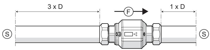
Fig. 2: Inlet and outlet pipe lengths
D: Outside diameter of the pipe
S: Interference
6.3 Installation position
▶ Install the unit so that the measuring pipe is always completely filled.
▶ Install in front of or in a rising pipe (figures 2 and 3).
▶ To ensure best possible empty pipe detection, install the device according to figure 1.
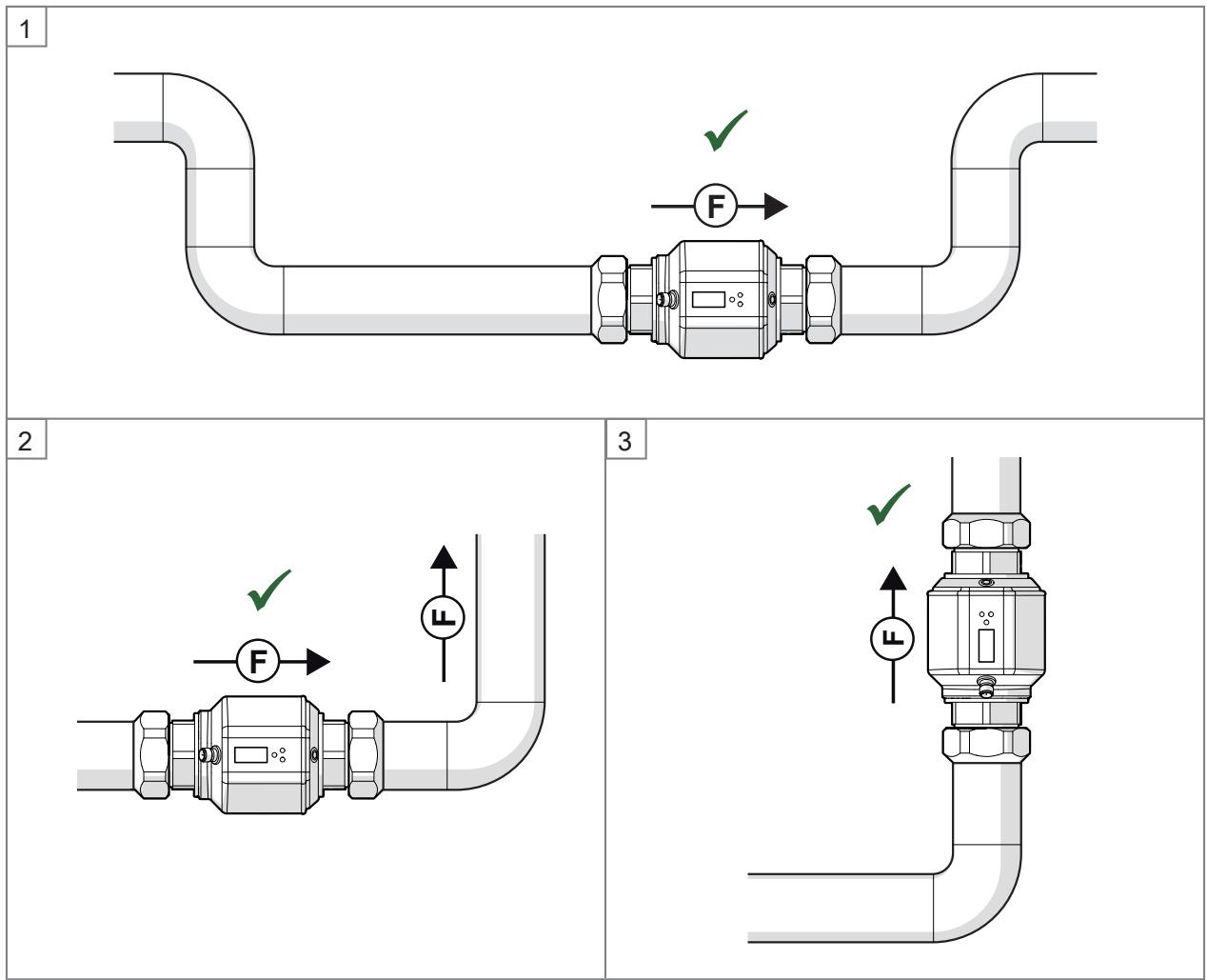
Fig. 3: Recommended mounting positions. F = flow direction

The unit can be installed independently of the orientation if the following is ensured:
- No air bubbles can form in the pipe system.
- The pipes are always completely filled.

In case of horizontal installation: as a result of horizontal mounting a small quantity of the medium always remains in the measuring channel, even after switching off the pump.
6.3.1 Non recommended installation position
• Directly in front of a falling pipe.
- In a falling pipe.
• Directly in front of the spout of a pipe.
• On the suction side of a pump.
- At the highest point of the pipe system.
7 Electrical connection

The unit must be connected by a qualified electrician.
Observe the national and international regulations for the installation of electrical equipment.
Voltage supply according to SELV, PELV.
▶ Disconnect power.
▶ Connect the unit as follows:


Fig. 4: Wiring diagram
| Pin | Connection |
| 1 | L+ |
| 3 | L- |
| 4 (OUT1) | Switching signal flow Frequency signal flow Switching signal totaliser Pulse signal totaliser Switching signal empty pipe detectionIO-Link |
| 2 (OUT2/InD) | Switching signal flow Switching signal temperature Analogue signal flow Analogue signal temperature Switching signal empty pipe detection Input for external totaliser reset |
Circuit examples:
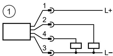


1: 2 x positive switching
3: 1 x positive switching / 1 x analogue
2: 2 x negative switching
4: 1 x negative switching / 1 x analogue
8 Operating and display elements

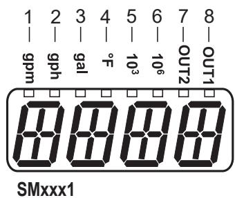

Fig. 5: Operating and display elements
The indicator LEDs 1...6 signal the unit to the displayed process value. The LEDs 7 and 8 indicate the switching status of the switching outputs.
The device keys can be used to switch between different process value displays during operation:
▶ Press ▲ or ▼ until the required display appears.
▷ The display switches between the views. The indicator LEDs signal the unit of the displayed value.
▷ After 30 s, the device returns to the standard display.
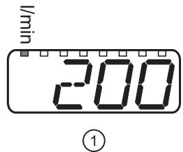

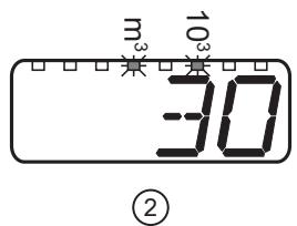


Fig. 6: Change between the views, example
1: Standard display: Display standard process value ➞ 34, Standard unit of measurement ➞ 28
2: Consumed quantity before the last totaliser reset
3: Temperature

The consumed quantity is automatically displayed in the unit of measurement providing the highest accuracy.
Meaning of the indicator LEDs depending on the device type:
| SMxxx0 | |
| Active indicator LED ●: | |
| 1: | Current flow volume in litres per minute |
| 2: | Current flow volume in cubic metres per hour |
| 3: | Current consumed quantity in litres since the last totaliser reset |
| 4: | Current consumed quantity in cubic metres since the last totaliser reset |
| 4+6: | Current consumed quantity in cubic metres x 103 since the last totaliser reset |
| 5: | Current medium temperature in °C |
| Flashing indicator LED ●: | |
| 3: | Consumed quantity in litres before the last totaliser reset |
| 4: | Consumed quantity in cubic metres before the last totaliser reset |
| 4+6: | Consumed quantity in cubic metres x 103 before the last totaliser reset |
| SMxxx1 | |
| Active indicator LED ●: | |
| 1: | Current flow volume in gallons per minute |
| 2: | Current flow volume in gallons per hour |
| 3: | Current consumed quantity in gallons since the last totaliser reset |
| 3+5: | Current consumed quantity in gallons x103 since the last totaliser reset |
| 3+6: | Current consumed quantity in gallons x106 since the last totaliser reset |
| 4: | Current medium temperature in °F |
| Flashing indicator LED ●: | |
| 3: | Consumed quantity in gallons before the last totaliser reset |
| 3+5: | Consumed quantity in gallons x103 before the last totaliser reset |
| 3+6: | Consumed quantity in gallons x106 before the last totaliser reset |
9 Menu
The figures in which the menus are displayed show the parameters that can be set on the unit by key input. These parameters and other functions are also available via the IO-Link interface.

Fig. 7: Menu overview
9.1 Main menu and submenus

The displayed parameters change when the factory setting is changed. The following menu displays show the maximum available parameters.

The designation of the parameters in the parameter setting software may differ from the designations in the device display.
Main menu:
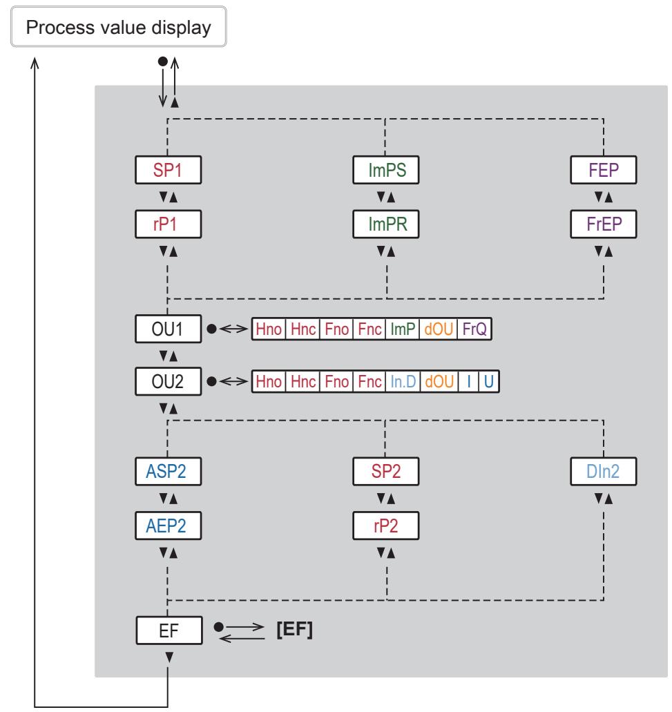
| Parameter | Explanation |
| SPx | Setpoint (hysteresis function) or upper limit value (window function) for switching output OUTx |
| rPx | Reset point (hysteresis function) or lower limit value (window function) for switching output OUTx |
| FEP | Frequency end point = Upper measured value at which the frequency signal set under FrEP is output. |
| FrEP | Frequency signal which is output when the upper measured value (VMR or FEP) is reached. |
| ImPS | Pulse value (= flow value at which 1 pulse is provided) |
| ImPR | Totaliser function: pulse signal (ImPR = YES) or switching signal (ImPR = no) |
| OUx | Output function for output OUTx:Hno/Fno/Hnc/Fnc = switching signal hysteresis/window, NO/NCImP = totaliser function (pulse signal or switching signal)dOU = switching signal diagnostics (fluid detection)FRQ = frequency signalI = analogue signal 4...20 mAU = voltage signal 0...10 VIn. D = totaliser reset via external signal |
| ASP2 | Analogue start point for OUT2 = process value at which the output signal is 4 mA (0 V). |
| AEP2 | Analogue end point for OUT2 = process value at which the output signal is 20 mA (10 V). |
| DIn2 | Reset signal for external totaliser reset |
| EF | Change to the EF (extended functions) submenu |
Menu extended functions EF:

| Parameter | Explanation |
| rES | Reset to factory settings |
| rTo | Setting of the totaliser reset (manually or time-controlled) |
| CFG | Change to the submenu CFG (basic settings) |
| MEM | Change to the MEM (memory) submenu |
| EPD | Change to the submenu EPD (empty pipe) |
| SIM | Change to the submenu SIM (simulation) |
Basic settings menu CFG:

| Parameter | Explanation |
| FOUx | Behaviour of output OUTx in case of an error |
| dSt | Start-up delay for volumetric flow monitoring |
| P-n | Output polarity for the switching outputs |
| dAP | Damping constant in seconds (63 % rise time τ). |
| diS | Update rate and orientation of the display |
| uni | Standard unit of measurement for flow |
| SELd | Standard process value of the display |
| SEL2 | Process value for output OUT2 |
| LFC | Low flow cut-off (= flow value below which flow is evaluated as standstill) |
| FPro | Counting method of the totaliser: consideration of the flow direction |
| Fdir | Direction of flow |
Memory MEM, fluid detection EPD and simulation SIM menus:
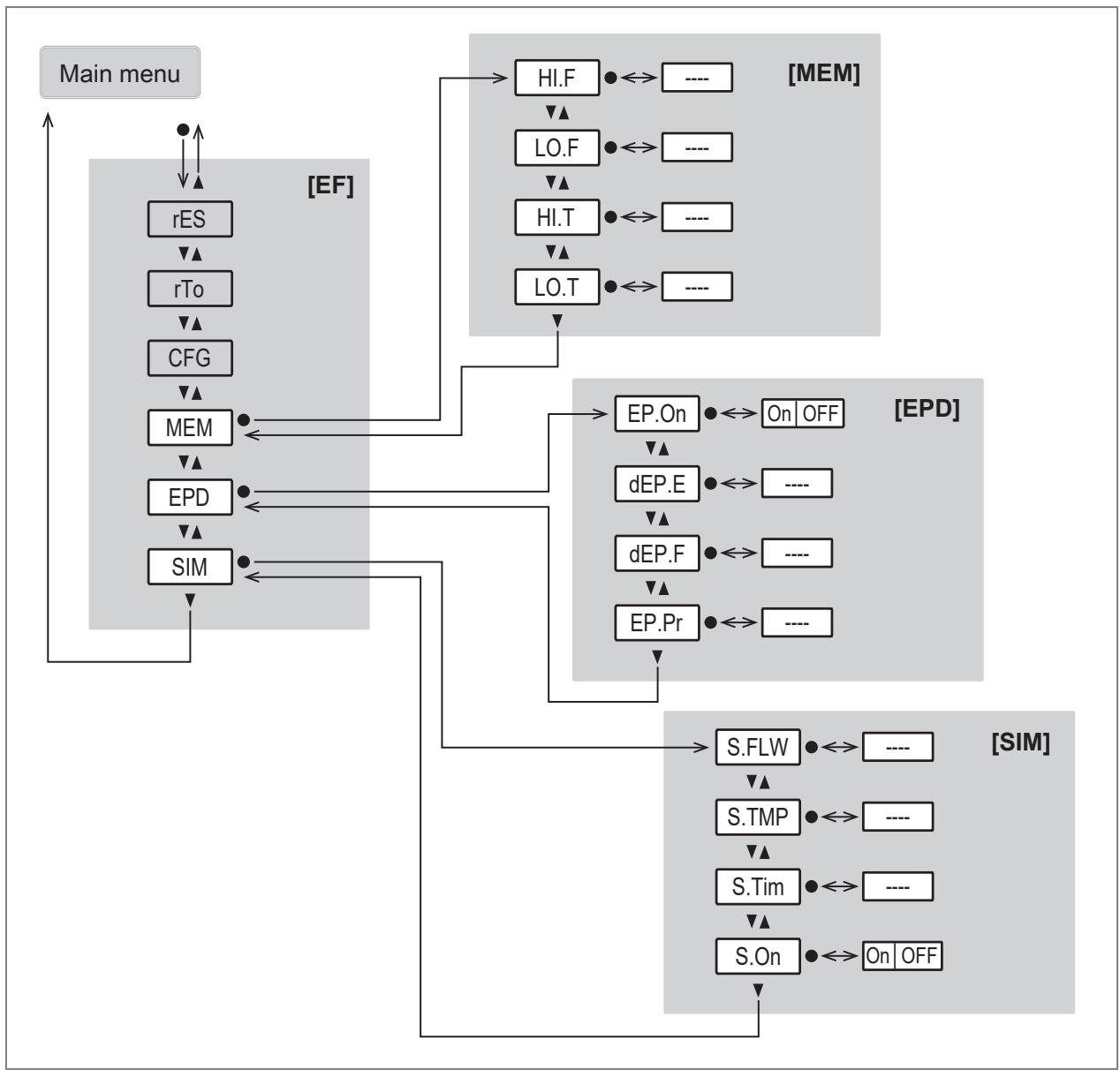
| Parameter | Explanation |
| Hi. F | Highest flow value measured |
| Lo. F | Lowest flow value measured |
| Hi. T | Maximum temperature value measured |
| Lo. T | Minimum measured temperature value |
| EP. On | Empty pipe detection on / off |
| dEP. E | Delay time empty signal |
| dEP. F | Delay time full signal |
| EP. Pr | Current state of empty pipe detection:EP. Pr = 200 %: pipe is filledEP. Pr = -100 %: pipe is empty |
| S. FLW | Simulated flow value in simulation mode |
| S. TMP | Simulated temperature value in simulation mode |
| S. Tim | Duration of the simulation in minutes |
| S. On | Starts the simulation mode |
10 Set-up
After power on and expiry of the power-on delay time, the unit is in the normal operating mode. It carries out its measurement and evaluation functions and generates output signals according to the set parameters.
During the power-on delay time, the outputs are in the following status according to the set parameters:
• ON with normally open function (Hno / Fno)
• OFF with normally closed function (Hnc / Fnc)
• 20 mA for current output (I)
• 10 V with voltage output (U)

When an IO-Link master is connected, the device automatically goes from SIO mode (standard input-output) into IO-Link mode if the port of the master is set to IO-Link mode.
11 Parameter setting
Parameter setting can be carried out via the IO-Link interface or via the operating elements on the unit.
Parameters can be set before installation or during operation.

If you change parameters during operation, this will influence the function of the plant.
▶ Ensure that there will be no malfunctions in your plant.
During parameter setting the unit remains in the operating mode. It continues to monitor with the existing parameter until the parameter setting has been completed.

Depending on the parameter setting, the parameters available in the menu may change.
11.1 Parameter setting via the unit keys

CAUTION
If the medium temperature is above 50\ °C ( 122\ °F ), parts of the housing can increase in temperature to over 65\ °C ( 149\ °F ).
▷ Risk of burns
▶ Do not touch the device with your hands.
▶ Use another object (e.g. a ballpoint pen) to carry out settings on the unit.
Parameter setting process in general:
| Intention | Action |
| Change from the process value display to the main menu | ● |
| Change to the submenu | Use ▼ to navigate to the submenu, e.g. EF, then ● |
| Select the required parameter | ▲ or ▼ |
| Change to the setting mode | ● |
| Modify the parameter value | ▲ or ▼ > 1 s |
| Apply the set parameter | ● |
| Exit parameter setting without saving | ▲ + ▼ |
| Return to the next higher menu level (repeat several times to reach process value display) | ▲ + ▼ |
| Return to the process value display | >30 seconds (timeout) |

If Loc is displayed when attempting to change a parameter value, the device keys are locked ➞ Lock / Unlock.

If S. Loc is displayed, the sensor is permanently locked via software. This locking can only be removed with a parameter setting software.
11.2 Parameter setting via IO-Link
The device parameters can be set via the IO-Link interface in the following ways, for example:
- Parameter setting via a suitable parameter setting software, e.g. ifm moneo|configure
• Parameter setting via a PLC
• Parameter setting via an IIoT application
Requirements for parameter setting via the IO-Link interface:
√ The Input Output Device Description (IODD) for the device in case of parameter setting via a parameter setting software, see documentation.ifm.com
√ The IO-Link interface description (PDF) for the device in case of parameter setting via a PLC or IIoT application, see documentation.ifm.com
√ An IO-Link master
▶ Connect the IO-Link master to the parameter setting software, the PLC or the IIoT application.
▶ Connect the device to a suitable free port of the IO-Link master.
▶ Set the port of the IO-Link master to the IO-Link operating mode.
▷ The device changes to the IO-Link mode.
▶ Change the parameter settings in the software.
▶ Write the parameter settings to the device.

Support for system integration and parameter setting via IO-Link:
→ Manual of the parameter setting software (e.g. moneo)
Explanations and startup packages at ifm.com/cnt/io-link-system-integration.
11.3 Output configuration
This chapter describes the options for the output signals at OUT1 and OUT2.
11.3.1 Switching signal for limit value monitoring
A switching signal can be output for process value monitoring. OUTx changes its switching state when the set switching limits are exceeded or not reached. You can choose between hysteresis and window function.

1: Process value
t: Time
SP: Set point
rP: Reset point
HY: Hysteresis
Hno: Hysteresis function NO (normally open)
Hnc: Hysteresis function NC (normally closed)
Fig. 8: Hysteresis function

When the hysteresis function is set, the switch point SP and the reset point rP are defined. rP must have a lower value than SP. If only the switch point is changed, the reset point is changed automatically; the difference remains constant.

1: Process value
t: Time
SP: Upper limit value
rP: Lower limit value
HY: Hysteresis
Fno: Window function NO (normally open)
Fnc: Window function NC (normally closed)
Fig. 9: Window function

When set to the window function the upper limit value SP and the lower limit value rP are defined. SP and rP have a fixed hysteresis of 0.25 % of the final value of the measuring range. This keeps the switching status of the output stable if the volumetric flow varies slightly.
Parameter setting via unit keys: Switching signal
√ The standard unit of measurement is selected: EF > CFG > Uni
√ Only for OUT2: the process value is selected: EF > CFG > SEL2.
▶ Call up the main menu.
Hysteresis function:
▶ Select OUx and set the switching signal: Hno or Hnc.
▶ Select SPx and set the measured value at which the output switches.
▶ Select rPx and set the measured value at which the output switches back.
Window function:
▶ Select OUx and set the switching signal: Fno or Fnc.
▶ Select SPx and set the upper limit value of the window.
▶ Select rPx and set the lower limit value of the window.
11.3.2 Analogue signal
The device provides an analogue signal proportional to the process value.
The analogue signal can be provided as current or voltage signal.
Within the measuring range the analogue signal is 4...20 mA (current output) or 0...10 V (voltage output).
The measuring range is scalable: the parameters ASP and AEP allow for the measuring range to be limited.
- ASP2 determines at which measured value the output signal is 4mA or 0 V.
• AEP2 determines at which measured value the output signal is 20 mA or 10V.

Minimum distance between ASP2 and AEP2 = 20 % of the final value of the measuring range.
If the measured value is outside the measuring range or in the event of an internal error, the current or voltage signals indicated in the following figure are provided.
For measured values outside the display range or in case of an error, messages are displayed (cr. UL, UL, OL, cr. OL, Err).

Fig. 10: Characteristic of the analogue output according to IEC 60947-5-2
1: Analogue signal MAW: Initial value of the measuring range
2: Measured value (Q: FLOW or T: TEMP) MEW: Final value of the measuring range
3: Detection range ASP: Analogue start point
4: Display range AEP: Analogue end point
5: Measuring range UL: Below the display range
6: Scaled measuring range cr. UL: Below the detection range
OL: Above the display range
cr. OL: Above the detection range

A negative flow value means flow against the flow direction ➞ 32 set under Fdir.

The analogue signal in case of a fault can be set via the parameter FOUx: Error behaviour of the outputs → 28.
Parameter setting via device buttons: Analogue signal
√ Standard unit of measurement is selected: EF > CFG > Uni.
√ Process value for OUT2 is selected: EF > CFG > SEL2.
▶ Call up the main menu.
▶ Select OU2 and set the analogue signal: I (4...20 mA) or U (0...10 V).
▶ Select ASP2 and set the measured value at which the minimum current or voltage value is provided.
▶ Select AEP2 and set the measured value at which the maximum current or voltage value is provided.
11.3.3 Frequency signal
The device provides a frequency signal proportional to the process value.
Within the measuring range the frequency signal is between 0 and 1 kHz for the factory setting.
The frequency signal is scalable: the parameter FrEP can be used to change the upper value of the frequency signal.
The measuring range is scalable: the parameter FEP can be used to reduce the upper value of the measuring range.
If the measured value is outside the measuring range or in the event of an internal error, the frequency signal indicated in the following figure is provided.
For measured values outside the display range or in case of a fault, messages are displayed (OL, Err).

Fig. 11: Output characteristics frequency output
| 1: | Frequency signal* | MAW: | Initial value of the measuring range |
| 2: | Flow | MEW: | Final value of the measuring range |
| 3: | Display range | FEP: | Frequency end point |
| 4: | Measuring range | FrEP: | Frequency signal (Hz) for the upper measured value |
| 5: | Scaled measuring range | OL: | Above the display range |
* Frequency signal in Hz. The reference value is the value set for FrEP. At factory setting, FrEP is = 1 kHz = 100 %.
Parameter setting via device buttons: Frequency signal
√ Standard unit of measurement is selected: EF > CFG > Uni.
▶ Call up the main menu.
▶ Select OU1 and set FRQ.
▶ Select FEP and set the upper value of the measuring range.
▶ Select FrEP and set the upper value of the frequency signal.
11.3.4 Consumed quantity monitoring (totaliser function)
The unit has an internal totaliser. The totaliser continuously sums up the consumed quantity and provides this process value both on the display and via the IO-Link interface.
In addition to the current consumed quantity, the value before the last reset is saved. This value and the time since the last reset can also be displayed.
→ Indication of the consumed quantity in the display: Operating and display elements → 13.
▷ The totaliser is reset automatically or manually.
→ Totaliser reset → 33.

The totaliser saves the totalled volumetric flow quantity every 10 minutes. After a power failure this value is available as the current meter reading. If a time-controlled reset is set, the elapsed time of the set reset interval is also saved. This means that the possible data loss can be maximum 10 minutes.
The totaliser takes account of the following parameter settings when totalising the consumed quantity:
- Flow direction ➕ 32.
- Counting method of the totaliser ➞ 32.
- Low flow cut-off ➕ 31.
A switching signal or pulse signals can be provided for consumed quantity monitoring:
→ Switching signal totaliser → 26
→ Pulse signal totaliser → 27
11.3.4.1 Switching signal totaliser
A switching signal can be provided for consumed quantity monitoring.
When the totaliser has totalled the volumetric flow quantity set under ImPS, the output provides a switching signal.
The output remains switched until a totaliser reset is carried out. When the totaliser has been reset, metering starts again.
The totaliser is reset automatically or manually.
The conditions for the totaliser reset and the switching signal can be set via the parameter rTo:
- rTo = OFF:
- The totaliser is only reset with a manual reset or after overflow.
- The output is switched when the totaliser has reached the flow quantity ImPS.
- rTo = ...h / d / w (hours / days / weeks):
- ▷ The totaliser is automatically reset after the set time.
- The output is only switched when the totaliser reaches the flow quantity ImPS by the set time.

The totaliser can be reset manually at any time or via an external signal on pin 2 ➞ 33.
Parameter setting via unit keys: Switching signal totaliser
√ Standard unit of measurement is selected: EF > CFG > Uni.
▶ Call up the main menu.
▶ Select OU1 and set ImP.
▶ Select ImPS and set the volumetric flow quantity at which the output switches.
- Press ▲ or ▼ to select the setting range.
- Briefly press ● to confirm the setting range.
- Press ▲ or ▼ to set the requested numeric value.
- Briefly press • to apply the value.

The setting range is displayed by the indicator LEDs and the shift of the decimal point in the four-digit display “ccccc”.
▶ Select ImPR and set no.
11.3.4.2 Pulse signal totaliser
Pulse signals can be provided for consumed quantity monitoring.
Every time the volumetric flow quantity (pulse value) set under ImPS has been reached, the output provides a pulse signal.
The pulse signal consists of a short switching on and off of the output. The switching status LEDs on the unit do not display the switching operation.

Pulse signals are not available via the IO-Link interface.
Parameter setting via device buttons: Pulse signal totaliser
√ Standard unit of measurement is selected: EF > CFG > Uni.
▶ Call up the main menu.
▶ Select ImPS and set the volumetric flow quantity at which 1 pulse is provided (pulse value).
- Press ▲ or ▼ to select the setting range.
- Briefly press • to confirm the setting range.
- Press ▲ or ▼ to set the requested numeric value.
- Briefly press • to apply the value.

The setting range is displayed by the indicator LEDs and the shift of the decimal point in the four-digit display “ccccc”.
▶ Select ImPR and set YES.
11.3.5 Switching signal empty pipe detection
The device recognises when both electrodes are not wetted by the medium and interprets this as an empty pipe. If the OUTx output is used for diagnostics, the device reports fluid detection via a switching signal, the display shows SEnS and the flow is set to zero.
The fluid detection can be activated or deactivated:
- EP. On = OFF:
The fluid detection is deactivated.
- EP. On = On
The fluid detection is activated.
A time delay can be set for the fluid detection.
11.3.5.1 Parameter setting via device buttons: Empty pipe detection
▶ Call up the main menu.
▶ Select OUx and set dOU.
▶ Go to the EF > EPD menu.
▶ Select EP. On and set On.
▶ Select dEP. E and set the delay time for the switching signal at empty pipe detection.
▶ Select dEP. F and set the delay time for the switching signal at full pipe detection.
Display the current value of the empty pipe detection:
▶ Go to the EF > EPD menu.
▶ Select EP. Pr and read the value (intermediate values are not displayed):
• 200 % = the pipe is filled.
- 100 % = the pipe is empty.
11.4 Application configuration
11.4.1 Standard unit of measurement
A unit of measurement can be selected with which the process value is shown in the display by default. All further parameter settings are based on this unit.
Changing the unit has no effect on the IO-Link process value, which is always transmitted in the SI unit.
Selectable values:
• Uni for SMxxx0: l/min; m³/h
• Uni for SMxxx1: gpm; gph

▶ Set the unit of measurement before configuring further parameters.
Parameter setting via device buttons: Standard unit of measurement
▶ Call up the menu EF > CFG.
▶ Select Uni and set the unit of measurement for the flow.
11.4.2 Error behaviour of the outputs
The response of the OUTx output in case of a fault can be set via the parameter FOUx. Depending on the selected output function, the following signals are provided in case of a fault:
- Switching signal:
- On: the output switches ON in case of a fault.
– OFF: the output switches OFF in case of a fault. - OU: the output switches irrespective of the fault as defined with the parameters.
- Analogue signal:
- On: the analogue signal goes to the upper end stop value.
- OFF: the analogue signal goes to the lower end stop value.
- OU: the analogue signal still corresponds to the measured value.
- Frequency signal:
- On: the frequency signal goes to 130% of FrP1.
– OFF: the frequency signal goes to 0 Hz. - OU: the frequency signal still corresponds to the measured value.

FOUx is not available for consumed quantity monitoring: Even in case of a fault, a switching or pulse signal is emitted when the set flow quantity is reached.
Parameter setting via unit keys: Error behaviour of the outputs
▶ Call up the menu EF > CFG.
▶ Select FOUx and set the error behaviour for OUTx: On, OFF, OU.
11.4.3 Start-up delay
The start-up delay dSt influences the switching outputs of the flow monitoring.
If the start-up delay is active (dSt > 0), the following applies: as soon as the flow quantity exceeds the LFC value ➞ 31, the following processes are carried out:
• The start-up delay is activated.
- The outputs switch as programmed: ON for NO function, OFF for NC function.
After activation of the start-up delay there are 3 options:
| Condition | Reaction | |
| 1: | The flow quantity increases quickly and reaches the switch point / acceptable range within dSt. | The outputs remain active. |
| 2: | The flow quantity increases slowly and does not reach the switch point / acceptable range within dSt. | The outputs are reset. |
| 3: | The flow quantity falls below LFC within dSt. | The outputs are reset at once; dSt is stopped. |
Example: flow monitoring with hysteresis function

| Condition | Reaction | |
| 1: | The flow quantity Q reaches LFC | dSt starts, the output becomes active |
| 2: | dSt elapsed, Q has reached SP | The output remains active |
| 3: | Q falls below SP but stays above rP | The output remains active |
| 4: | Q falls below rP | The output is reset |
| 5: | Q reaches LFC again | dSt starts, the output becomes active |
| 6: | dSt elapsed, Q has not reached SP | The output is reset |
| 7: | Q reaches SP | The output becomes active |
Example: flow monitoring with window function

| Condition | Reaction | |
| 1: | The flow quantity Q reaches LFC | dSt starts, the output becomes active |
| 2: | dSt elapsed, Q has reached acceptable range | The output remains active |
| 3: | Q above SP (leaves acceptable range) | The output is reset |
| 4: | Q falls below SP again | The output becomes active |
| 5 | Q falls below rP (leaves acceptable range) | The output is reset |
| 6 | Q reaches LFC again | dSt starts, the output becomes active |
| 7 | dSt elapsed, Q has not reached acceptable range | The output is reset |
| 8 | Q reaches acceptable range | The output becomes active |
Parameter setting via device buttons: Start-up delay
▶ Call up the menu EF > CFG.
▶ Select dSt and set a start-up delay in seconds.
11.4.4 Output polarity of the switching outputs
The output polarity is set via the parameter P-n.
The setting affects both switching outputs.
- PnP: The switching output is positive switching.
- nPn: The switching output is negative switching.
Parameter setting via unit keys: Output polarity
▶ Call up the menu EF > CFG.
▶ Select P-n and set PnP or nPn.
11.4.5 Damping
The set damping constant stabilises the output signals. Abrupt changes in the physical process values are smoothed out.
This concerns the outputs, the display and the process value transmission via the IO-Link interface.
The damping constant dAP is used to set after how many seconds the output signal reaches 63 % of the final value if the measured value changes suddenly.
The damping constant is added to the response time of the sensor (→ Technical data).
The signals UL, cr. UL, OL and cr. OL are defined under consideration of the damping constant.

Measured value damping only has an effect on the process value flow.
Parameter setting via device buttons: Damping
▶ Call up the menu EF > CFG.
▶ Select dAP and set the damping time in seconds ( τ -value 63 %).
11.4.6 Low flow cut-off
Low flow quantities can be ignored using the parameter LFC (Low flow cut-off). Flow below the LFC value is evaluated by the sensor as standstill (Q = 0).
The LFC value influences:
• the process value for flow shown on the display
• The switching signal for flow
• the analogue signal for flow
• The frequency signal for flow
• the consumed quantity monitoring (switching or pulse signal for flow)
- The totalisation of the consumed quantity by the totaliser.
• the memory values for minimum and maximum flow
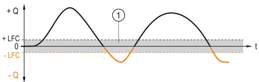
Fig. 12: Low flow cut-off
+LFC: Minimum flow in positive flow direction
-LFC: Minimum flow in negative flow direction
1: Flow which is evaluated as standstill
Parameter setting via unit keys: low flow cut-off
▶ Call up the menu EF > CFG.
▶ Select LFC and set the limit below which a flow is evaluated as standstill.
11.4.7 Flow direction
The positive flow direction can be defined by the user. This setting also affects the consumed quantity monitoring ➕ 32.
An arrow with the text “flow direction” on the device indicates the positive flow direction (factory setting).
The direction of the flow rate measurement can be reversed using the parameter Fdir:
| Fdir | Direction of flow |
| + | Flow direction in case of factory setting |
| - | Flow direction contrary to the factory setting |
Parameter setting via unit keys: flow direction
▶ Call up the menu EF > CFG.
▶ Select Fdir and set the direction of media flow.
11.4.8 Counting method of the totaliser
The totaliser takes account of the flow direction when totalising the consumed quantity ➞ 32.
The following counting methods can be defined via the parameter FPro:
| FPro | Counting method |
| 0+ | Negative flow values (against the marked flow direction) are not taken into account for totalisation of the consumed quantity. |
| -+ | Negative flow values (against the marked flow direction) are subtracted from the consumed quantity. |
The counting method affects the output signals for consumed quantity monitoring.
→ Consumed quantity monitoring (totaliser function) → 25

Fig. 13: Taking into account the flow direction when totalising the consumed quantity
+Q: Flow quantity in positive direction
-Q: Flow quantity in negative direction
V: Flow quantity absolute (= sum of negative and positive flow)
1: Flow changes to negative direction
2: Flow changes to positive direction
3: Flow taken into account for totalisation
When the direction of flow is changed, the minimum flow quantity LFC is taken into account.
→ Figure low flow cut-off → 31.
Parameter setting via device buttons: Counting method of the totaliser
▶ Call up the menu EF > CFG.
▶ Select FPro and set the counting method for the totaliser.
11.4.9 Totaliser reset
There are different ways to reset the totaliser:
| Type of reset | Parameter | |
| 1. | Manual reset | rTo = rES. T |
| 2. | Time-controlled reset | rTo = ... h = hours ... d = days ... w = weeks |
| 3. | Reset via external signal | OU2 = In. DDIn2: +EDG = reset for rising edge -EDG = reset for falling edge HIGH = reset for high signal LOW = reset for low signal |
| 4. | Reset via overflow (maximum display range is reached) | rTo = OFF |
If the totaliser is reset in one of the above ways, the output is also reset in the case of consumed quantity monitoring.
→ Switching signal totaliser → 26.
Parameter setting via unit keys: Totaliser reset
1. Manual reset:
▶ Select the EF menu.
▶ Select rTo and set rES. T.
▷ The totaliser is reset.
2. Time-controlled reset:
▶ Select the EF menu.
▶ Select rTo, then set the time in weeks (w), days (d) or hours (h).
The totaliser is automatically reset after the set time.
3. Reset via external signal:
▶ Call up the main menu.
▶ Select OU2 and set the digital input: In. D.
▶ Select DIn2 and set the reset signal: HIGH, LOW, +EDG or -EDG.
▷ The totaliser is reset when receiving the reset signal via pin 2.
4. Reset via overflow:
▶ Select the EF menu.
▶ Select rTo and set OFF.
The totaliser is reset as soon as the maximum display range is exceeded.
11.4.10 Lock / unlock
The unit can be locked electronically to prevent unauthorised setting.
This lock prevents the settings from being changed via the keys on the unit.
Factory setting: not locked.
Parameter setting via unit keys: lock / unlock
Lock:
▶ Make sure that the unit is in the normal operating mode.
▶ Press ▲ and ▼ simultaneously for 10 s until Loc is displayed.
Unlock:
▶ Make sure that the unit is in the normal operating mode.
▶ Press ▲ and ▼ simultaneously for 10 s until uLoc is displayed.
11.4.11 Device reset
The unit can be reset to factory settings.

We recommend documenting your own settings in the chapter Factory setting before carrying out a reset.
Parameter setting via unit keys: Device reset
▶ Select the EF menu.
▶ Select rES.
▶ Briefly press ●.
▶ Keep ▲ or ▼ pressed.
▷ ---- is displayed.
▶ Briefly press ●.
▷ The unit carries out a reboot.
11.5 Display
11.5.1 Display standard process value
Use the SELd parameter to choose which process value is shown in the display by default.
Selectable values:
- FLOW: the display shows the current process value for flow.
• TEMP: the display shows the current process value for temperature.
- TOTL: the display indicates the current counter reading of the totaliser.

The consumed quantity is automatically displayed in the unit of measurement providing the highest accuracy.
Parameter setting via unit keys: Display standard process value
▶ Call up the menu EF > CFG.
▶ Select SELd and set the standard process value.
11.5.2 Display update rate and rotation
The update frequency and the orientation of the display can be set via the parameter diS.

The rotation and the update rate are set via a common parameter.
Selectable values:
• d1: 0° rotation with update rate d1 (fast)
• d2: 0° rotation with update rate d2 (medium)
• d3: 0° rotation with update rate d3 (slow)
- rd1: 180° rotation with update rate d1 (fast)
- rd2: 180° rotation with update rate d2 (medium)
- rd3: 180° rotation with update rate d3 (slow)
Parameter setting via unit keys: Display update rate
▶ Call up the menu EF > CFG.
▶ Select diS and set the update rate.
11.5.3 Switch off the display
The process value display can be permanently switched off in the operating mode.
Pressing a key switches the display on. In case of inactivity, the display switches off again after a few seconds.

The LEDs remain active even if the display is deactivated. Error messages are displayed even if the display is deactivated.
Parameter setting via unit keys: Display off
▶ Call up the menu EF > CFG.
▶ Select diS and set OFF.
11.6 Diagnostics and service functions
11.6.1 Device information
Unalterable device information is stored on the unit. This includes:
- Product name
- Product ID
- Serial number
- Hardware revision
- Software revision
In addition, a freely definable application-specific tag with a maximum length of 32 characters can be assigned to the device.

This function is only available via the IO-Link interface.
11.6.2 Memory
The unit stores the maximum and minimum measured process values.
The current value can be read from the unit's display or via the IO-Link interface.
Selectable values:
• Lo. F: Minimum value memory for volumetric flow
• Hi. F: Maximum value memory for volumetric flow
• Lo. T: Minimum value memory for temperature
• Hi. T: Maximum value memory for temperature

The stored values can only be reset via the IO-Link interface.

It makes sense to delete the memories as soon as the unit operates under normal operating conditions for the first time.
Parameter setting via unit keys: Memory
Show memory:
▶ Go to the EF > MEM menu.
▶ Select LO.x or HI.x to show the highest or lowest process value measured.
Clear memory:
▶ Go to the EF > MEM menu.
▶ Select LO.x or HI.x.
▶ Briefly press ●.
▶ Keep ▲ or ▼ pressed.
▷ ---- is displayed.
▶ Briefly press ●.

It makes sense to delete the memories as soon as the unit operates under normal operating conditions for the first time.
11.6.3 Simulation
With this function, process values are simulated and their signal path is checked.
Process values that lead to an error message or warning can be simulated (e.g. OL).
When the simulation is started, the values of the totaliser are frozen and the simulated totaliser is set to 0. The simulated flow value then has an effect on the simulated totaliser. When the simulation is ended, the initial totaliser values are restored.
During the simulation:
- The simulation has no effect on the current process values. The outputs operate as previously set.
- The original totaliser value remains saved without any changes even if there is a real flow.
- No error messages of the current application are available. They are suppressed by the simulation.
The following values can be simulated:
Volumetric flow, temperature, UL (below the display range), OL (above the display range), Err (error), SENS (empty pipe).
Parameter setting via unit keys: simulation
▶ Go to the EF > SIM menu.
▶ Select S. FLW and set the flow value to be simulated, UL, OL, Err or SENS.
▶ Select S. TMP and set the temperature value to be simulated, UL, OL or Err.
▶ Select S. Tim and set the time of the simulation in minutes.
▶ Select S. On and set the function:
- On: The simulation starts. The values are simulated for the time set under S. Tim. Abort by pressing any key.
• OFF: The simulation is not active.
12 Troubleshooting
The device provides self-diagnostic options. It monitors itself automatically during operation.
Warnings and error states are displayed even if the display is switched off.
If several diagnostic events occur simultaneously, only the diagnostic message of the event with the highest priority is displayed.
12.1 Warning messages
| Indication | Problem/remedy |
| SEnS | Sensor signal invalid. Measuring pipe not sufficiently filled. ▶ Check the installation position (⇨ chapter Installation). Medium with too low a conductivity. ▶ Verify the conductivity of the medium (≥ 20 μS/cm). |
| Loc | Setting keys on the unit locked, parameter change rejected. ▶ Unlock the unit using the unit keys. |
| C. Loc | Setting buttons on the unit temporarily locked, parameter setting via IO-Link communication active. ▶ Finish parameter setting via IO-Link communication. |
| S. Loc | Setting keys locked via parameter setting software, parameter change rejected. ▶ Unlock the unit via IO-Link interface using the parameter setting software. |
| OL | Above the display range. ▶ Check the measuring range. |
| UL | Below the display range. ▶ Check the measuring range. |
| SC1 | Switching status LED for OUT1 flashing: short circuit OUT1. ▶ Check switching output OU1 for short circuit or excessive current. |
| SC2 | Switching status LED for OUT2 flashing: short circuit OUT2. ▶ Check switching output OUT2 for short circuit or excessive current. |
| SC | Switching status LEDs for OUT1 and OUT2 flashing: short circuit OUT1 and OUT2. ▶ Check switching outputs OUT1 and OUT2 for short circuit or excessive current. |
12.2 Error messages
| Indication | Problem/remedy |
| IOE.n | Malfunctioning. The unit is defective.► ▶ Replace the unit. |
| Display off | Supply voltage too low.► ▶ Check the supply voltage. Display switched off.► Check whether diS=OFF is set and change setting if necessary. |
| cr. OL | Above the measuring range.► ▶ Check the measuring range. |
| cr. UL | Below the measuring range.► ▶ Check the measuring range. |
| PARA | Parameter setting outside the valid range.► ▶ Check parameter setting. |

Information on the display and detection range: Analogue signal ➞ 24.
13 Maintenance, repair and disposal
The operation of the unit is maintenance-free.
Only the manufacturer is allowed to repair the unit.
▶ After use dispose of the device in an environmentally friendly way in accordance with the applicable national regulations.
14 Factory setting
| Parameter | Factory setting | User settings | |
| SMxxx0: | SMxxx1: | ||
| SP1 | 20 % MEW | 20 % MEW | |
| rP1 | 19.5 % MEW | 19.5 % MEW | |
| ImPS | 0.1 | 0.02 | |
| ImPR | YES | YES | |
| OU1 | Hno | Hno | |
| OU2 | I | I | |
| SP2 (FLOW) | 40 % MEW | 40 % MEW | |
| rP2 (FLOW) | 39.5 % MEW | 39.5 % MEW | |
| SP2 (TEMP) | 20 °C | 68 °F | |
| rP2 (TEMP) | 19.6 °C | 67.3 °F | |
| ASP2 (FLOW) | 0 % MEW | 0 % MEW | |
| AEP2 (FLOW) | 100 % MEW | 100 % MEW | |
| ASP2 (TEMP) | -20 °C | -4 °F | |
| AEP2 (TEMP) | 80 °C | 176 °F | |
| FEP | 100 % MEW | 100 % MEW | |
| FrEP | 1 kHz | 1 kHz | |
| FDir | + | + | |
| FPro | - + | - + | |
| LFC | 5 l/min | 1.1 gpm | |
| DIn2 | +EDG | +EDG | |
| FOU1 | OFF | OFF | |
| FOU2 | OFF | OFF | |
| dSt | 0 | 0 | |
| P-n | PnP | PnP | |
| dAP | 0.6 s | 0.6 s | |
| rTo | OFF | OFF | |
| diS | d2 | d2 | |
| Uni | Lmin | gpm | |
| SELd | FLOW | FLOW | |
| SEL2 | FLOW | FLOW | |
| EP. On | OFF | OFF | |
| dEP. E | 0 s | 0 s | |
| dEP. F | 2 s | 2 s | |
| S. FLW | 20% | 20% | |
| S. TMP | 20 °C | 68 °F | |
| S. Tim | 3 min | 3 min | |
MEW = final value of the measuring range
- 1 PRELIMINARY NOTE
- 1.1 SYMBOLS USED
- 1.2 WARNINGS
- 2 SAFETY INSTRUCTIONS
- 2.1 CYBERSECURITY
- 3 TRANSPORT, HANDLING AND STORAGE
- 4 INTENDED USE
- 4.1 APPLICATION AREA
- 4.2 NOTE REGARDING SM0510 AND SM2130
- 5 FUNCTION
- 5.1 OUTPUT OUT1 SELECTION OPTIONS
- 5.2 OUTPUT OUT2 SELECTION OPTIONS
- 5.3 IO-LINK
- 6 MOUNTING
- 6.1 PROCESS CONNECTION
- 6.2 INTERFERENCE
- 6.3 INSTALLATION POSITION
- 7 ELECTRICAL CONNECTION
- 8 OPERATING AND DISPLAY ELEMENTS
- 9 MENU
- 9.1 MAIN MENU AND SUBMENUS
- 10 SET-UP
- 11 PARAMETER SETTING
- 11.1 PARAMETER SETTING VIA THE UNIT KEYS
- 11.2 PARAMETER SETTING VIA IO-LINK
- 11.3 OUTPUT CONFIGURATION
- 11.3.1 SWITCHING SIGNAL FOR LIMIT VALUE MONITORING
- 11.3.2 ANALOGUE SIGNAL
- 11.3.3 FREQUENCY SIGNAL
- 11.3.4 CONSUMED QUANTITY MONITORING (TOTALISER FUNCTION)
- 11.3.4.1 SWITCHING SIGNAL TOTALISER
- 11.3.4.2 PULSE SIGNAL TOTALISER
- 11.3.5 SWITCHING SIGNAL EMPTY PIPE DETECTION
- 11.4 APPLICATION CONFIGURATION
- 11.4.1 STANDARD UNIT OF MEASUREMENT
- 11.4.2 ERROR BEHAVIOUR OF THE OUTPUTS
- 11.4.3 START-UP DELAY
- 11.4.4 OUTPUT POLARITY OF THE SWITCHING OUTPUTS
- 11.4.5 DAMPING
- 11.4.6 LOW FLOW CUT-OFF
- 11.4.7 FLOW DIRECTION
- 11.4.8 COUNTING METHOD OF THE TOTALISER
- 11.4.9 TOTALISER RESET
- 11.4.10 LOCK / UNLOCK
- 11.4.11 DEVICE RESET
- 11.5 DISPLAY
- 11.5.1 DISPLAY STANDARD PROCESS VALUE
- 11.5.2 DISPLAY UPDATE RATE AND ROTATION
- 11.5.3 SWITCH OFF THE DISPLAY
- 11.6 DIAGNOSTICS AND SERVICE FUNCTIONS
- 11.6.1 DEVICE INFORMATION
- 11.6.2 MEMORY
- 11.6.3 SIMULATION
- 12 TROUBLESHOOTING
- 12.1 WARNING MESSAGES
- 12.2 ERROR MESSAGES
- 13 MAINTENANCE, REPAIR AND DISPOSAL
- 14 FACTORY SETTING
Brand : IFM
Model : SM2000
Category : Detector