Autopulse 220M2 - Welding machine GYS - Free user manual and instructions
Find the device manual for free Autopulse 220M2 GYS in PDF.
User questions about Autopulse 220M2 GYS
0 question about this device. Answer the ones you know or ask your own.
Ask a new question about this device
Download the instructions for your Welding machine in PDF format for free! Find your manual Autopulse 220M2 - GYS and take your electronic device back in hand. On this page are published all the documents necessary for the use of your device. Autopulse 220M2 by GYS.
USER MANUAL Autopulse 220M2 GYS
natural_image
Technical line drawing of three identical industrial electrical cabinets with wheels and ventilation slots (no text or symbols)| FR | 02-08 / 9-20 / 93-104 |
| EN | 02-08 / 21-32 / 93-104 |
| DE | 02-08 / 33-44 / 93-104 |
| ES | 02-08 / 45-56 / 93-104 |
| RU | 02-08 / 57-68 / 93-104 |
| NL | 02-08 / 69-80 / 93-104 |
| IT | 02-08 / 81-92 / 93-104 |
AUTOPULSE M1 M2 M3
Générateur MIG/MAG MIG/MAG welding machine Schweissgerät für MIG/MAG Equipo de soldadura MIG/MAG Сварочный аппарат МИГ/МАГ MIG/MAG lasapparaat Dispositivo saldatura MIG/MAG
text_image
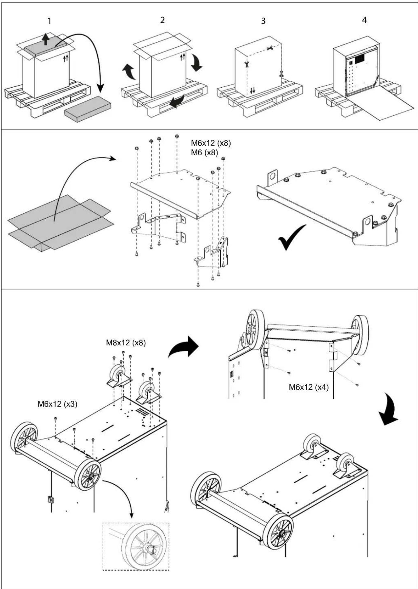
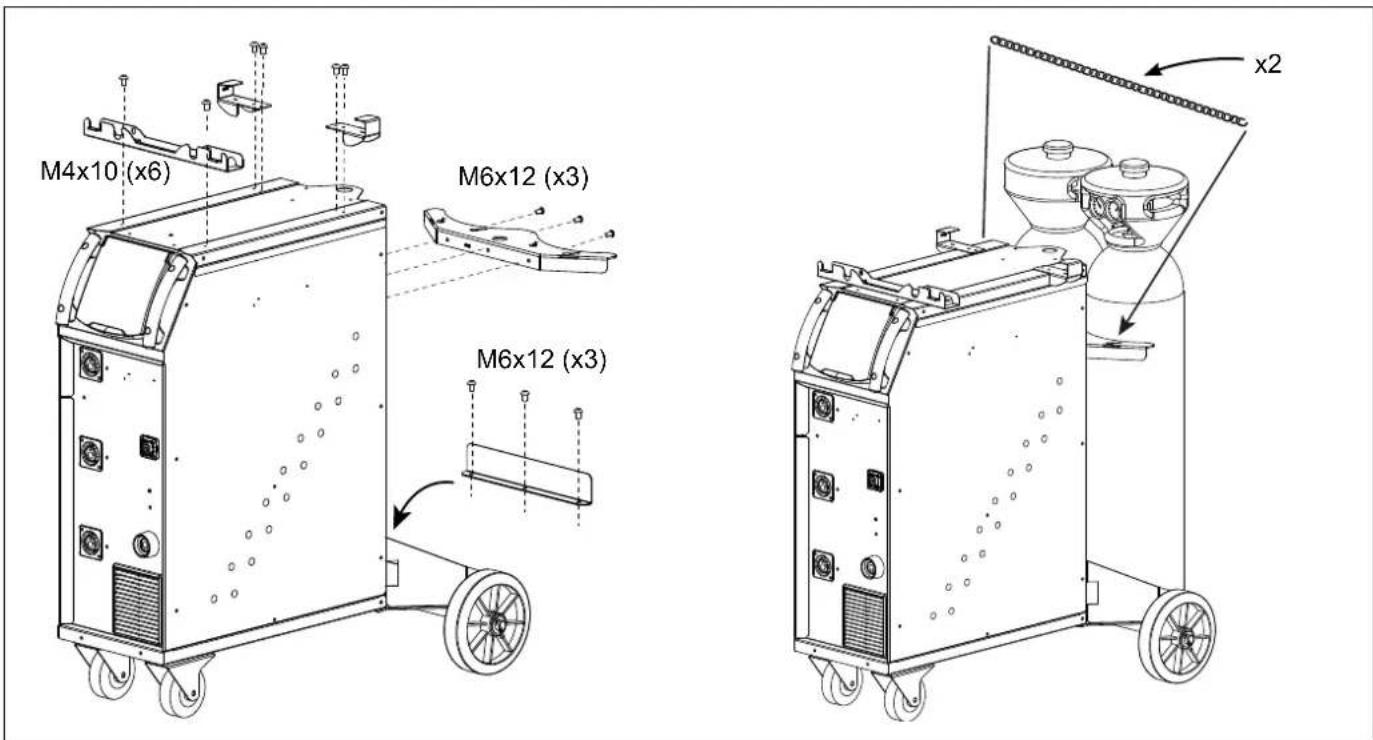
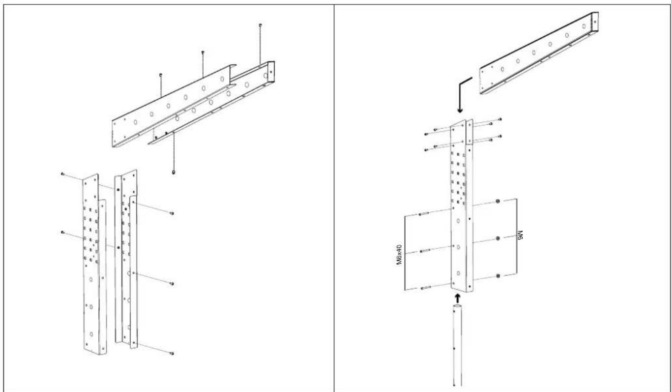
M4x10 (x6) M6x12 (x3) M6x12 (x3) x2POTENCE SEULE / BALANCING ARM ONLY / AUSLEGER / SOPORTE SOLO / KPOHШТЕЙН / STEUN ALLEEN / BRACCIO DI SOSTEGNO SINGOLO | 052976
M6X12 M6X40 M6


X 26 X 3 X 3
text_image
Technical diagram showing assembly of a structural panel with labeled components and dimensions
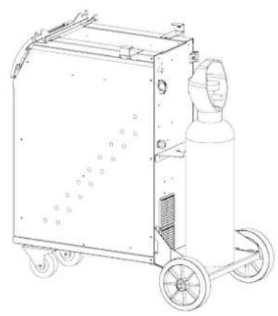
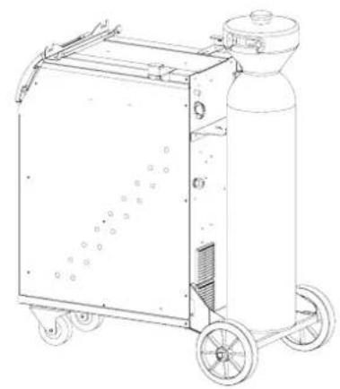
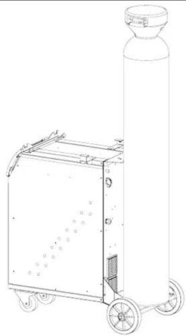
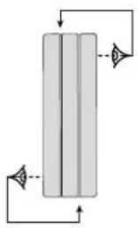
SUPPORT BOUTEILLE / BOTTLE SUPPORT / FLASCHENHALTER / PORTABOTELLAS / FLESSENHOU-DER / PORTABOTTIGLIE
AUTOPULSE 220-M1 | 230 V + 208/240 V
FR Utiliser les vis présentes sur la face arrière afin de fixer le support bouteille adapté.
EN Use the screws on the rear panel to fix the appropriate bottle holder.
DE Verwenden Sie die Schrauben an der Rückwand, um den entsprechenden Flaschenhalter zu befestigen.
ES Utilice los tornillos del panel trasero para fijar el portabotellas apropiado.
RU Используйте винты на задней панели для крепления соответствующего держателя бутылок.
NL Gebruik de schroeven op het achterpaneel om de juiste flessenhouder te bevestigen.
Utilizzare le viti sul pannello posteriore per fissare il portabottiglie appropriato.
natural_image
Line drawing of a mechanical device with wheels and a cylindrical housing (no text or symbols)2,5 m³
natural_image
Line drawing of a portable industrial machine with wheels and a cylindrical top (no text or symbols)4 m3 10 m3
natural_image
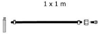
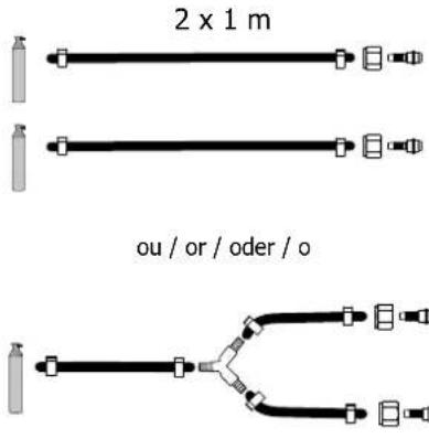
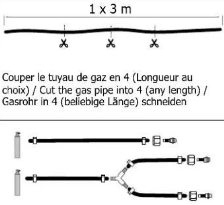
Line drawing of a cylindrical industrial machine with wheels and a top-mounted cylindrical component (no text or symbols)RACCORD GAZ / GAS FITTINGS / GASANSCHLUSS / CONEXIÓN DE GAS / ГАЗОВОЕ СОЕДИНЕНИЕ / GAS AANSLUITING / COLLEGAMENTO GAS | M1 : 1 x 1 m | M2 : 2 x 1 m | M3 : 1 x 3 m
| Autopulse 220-M1 Autopulse 220-M2 Autopulse 220-M3 | ||
 |  |  |
|
AUTOPULSE M1

text_image
Technical diagram of a mechanical device with numbered components and directional arrows indicating flow or assembly.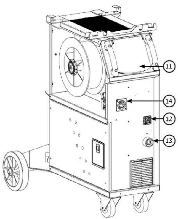
text_image
Technical diagram of a mechanical device with numbered components labeled 11, 12, 13, and 14.AUTOPULSE M2
text_image
Technical diagram of a mechanical device with numbered components and labeled parts in Chinese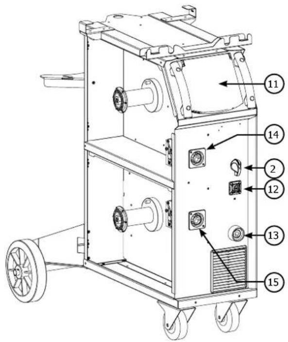
text_image
Technical diagram of a mechanical device with numbered components for identificationAUTOPULSE M3
text_image
Technical diagram of a mechanical device with numbered components and labeled parts in Chinese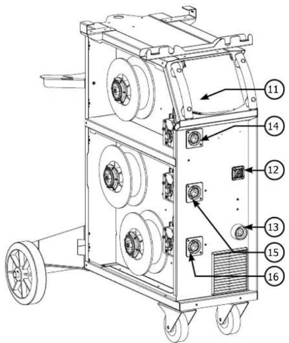
text_image
Technical diagram of a mechanical device with numbered components and directional arrows indicating assembly or movement.II
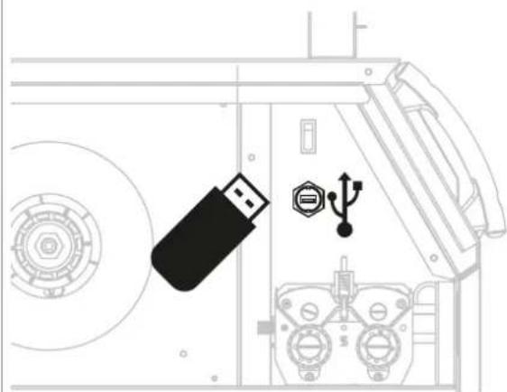
1ÈRE UTILISATION / ERSTE VERWENDUNG / FIRST USE / ПЕРВОЕ ИСПОЛЬЗОВАНИЕ / I° UTILIZZO / EERSTE GEBRUIK / PRIMERA UTILIZACIÓN
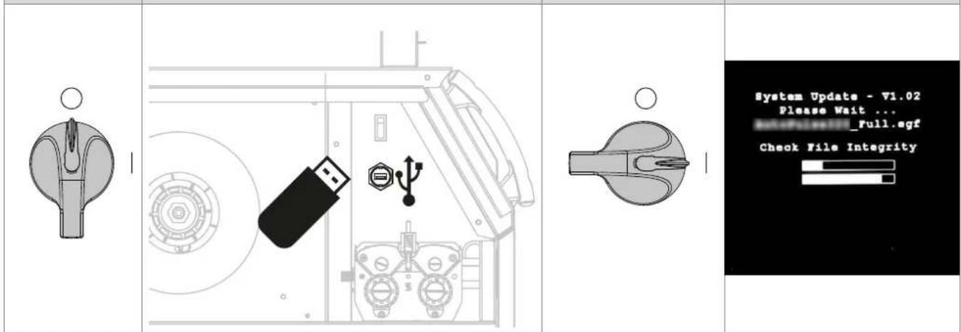
FR Avant la première utilisation de votre appareil, merci de vérifier la présence de nouvelles mises à jour.
EN Before using your device for the first time, please check for new updates.
DE Vor der ersten Anwendung des Gerätes bitte prüfen Sie, ob neue Softwareaktualisierungen verfügbar sind.
ES Antes del primer uso de su aparato, compruebe la presencia de nuevas actualizaciones.
RU Перед тем как использовать аппарат проверьте нет обновлений программного обеспечения.
NL Voordat u het apparaat voor de eerste keer gebruikt, moet u de aanwezigheid van nieuwe updates controleren.
Prima di utilizzare per la prima volta il vostro apparecchio, vogliate verificare se ci sono nuovi aggiornamenti.
1234
text_image
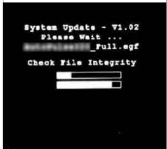
System Update - V1.02 Please Wait ... AutoRele Reduction_Full.egf Check File Integrity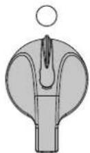
natural_image
Technical line drawing of a device interior with a USB flash, connector, and switch symbol (no text or labels)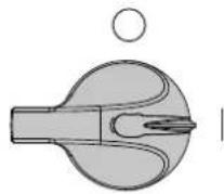
text_image
System Update - V1.02 Please Wait ... AutoPulse339_Full.sgf Check File IntegrityFR Insérer la clé usb fournie dans son port dédié puis démarrer l'appareil.
EN Insert the supplied USB flash drive into its dedicated port and start the device.
DE Stecken Sie den mitgelieferten USB-Stick in den dafür vorgesehenen Anschluss und starten Sie das Gerät.
ES Inserte la tarjeta USB incluida en el puerto USB e inicie el aparato.
RU Вставьте входящую в комплект USB флешку в предназначенный для этого порт и включите аппарат.
NL Breng de meegeleverde USB-stick in en start het apparaat.
Inserire la chiavetta USB fornita nella porta dedicata e avviare l'apparecchio.

FR L'écran ci-dessus apparait si une nouvelle version est détectée.
EN The above screen appears if a new version is detected.
DE Der obige Bildschirm erscheint, wenn eine neue Version erkannt wird.
ES La pantalla inferior aparece si se detecta una nueva versión.
RU Указанный ниже экран
отобразится если есть
в наличии новая версия
программы.
NL Het hierboven getoonde scherm verschijnt indien een nieuwe versie is gedetecteerd.
IT Sullo schermo si potrà vedere se è stata rilevata una nuova versione.
AVERTISSEMENTS - RÈGLES DE SÉCURITÉ
CONSIGNE GÉNÉRALE
INSTALLATION – FONCTIONNEMENT PRODUIT
INTERFACE HOMME-MACHINE (IHM)

IHM
natural_image
Technical line drawing of a mechanical assembly with labeled components (a, b, d), no readable text or symbols present.natural_image
Pure diagram of a vertical cylindrical structure with directional arrows indicating flow or movement (no text or symbols)natural_image
Technical line drawing of a mechanical assembly with gears and housing (no text or symbols)text_image
Istart I hot start T hotstart Dstart Gas Pre-Flow Creep Speed Soft-start I crash Filler I crater Filler I burn-back I blackout T burn-back T crater Filler Gas post-Flowtext_image
I start I hot start I start Dstart 4T Gas Pre-Flow Creep Speed Soft-start I hot start I hot start I burn-back I Blackout 4T Gas post-Flow T burn-back T crater Filler I crater Fillertext_image
I start I hot start T hotstart Dstart Gas Pre-Flow Creep Speed Soft-start T upslope T downslope I burn-back I blackout Gas post-Flow T burn-back T crater Filler I crater Fillertext_image
I hotstart I start Hot start Dstart T upslope 4T Gas Pre-Flow Creep Speed Soft-start I Crater Filler T Crater Filler T upslope T downslope I Blackout T burn-back Gas post-Flow T burn-backANOMALIES, CAUSES, REMÈDES
CONDITIONS DE GARANTIE
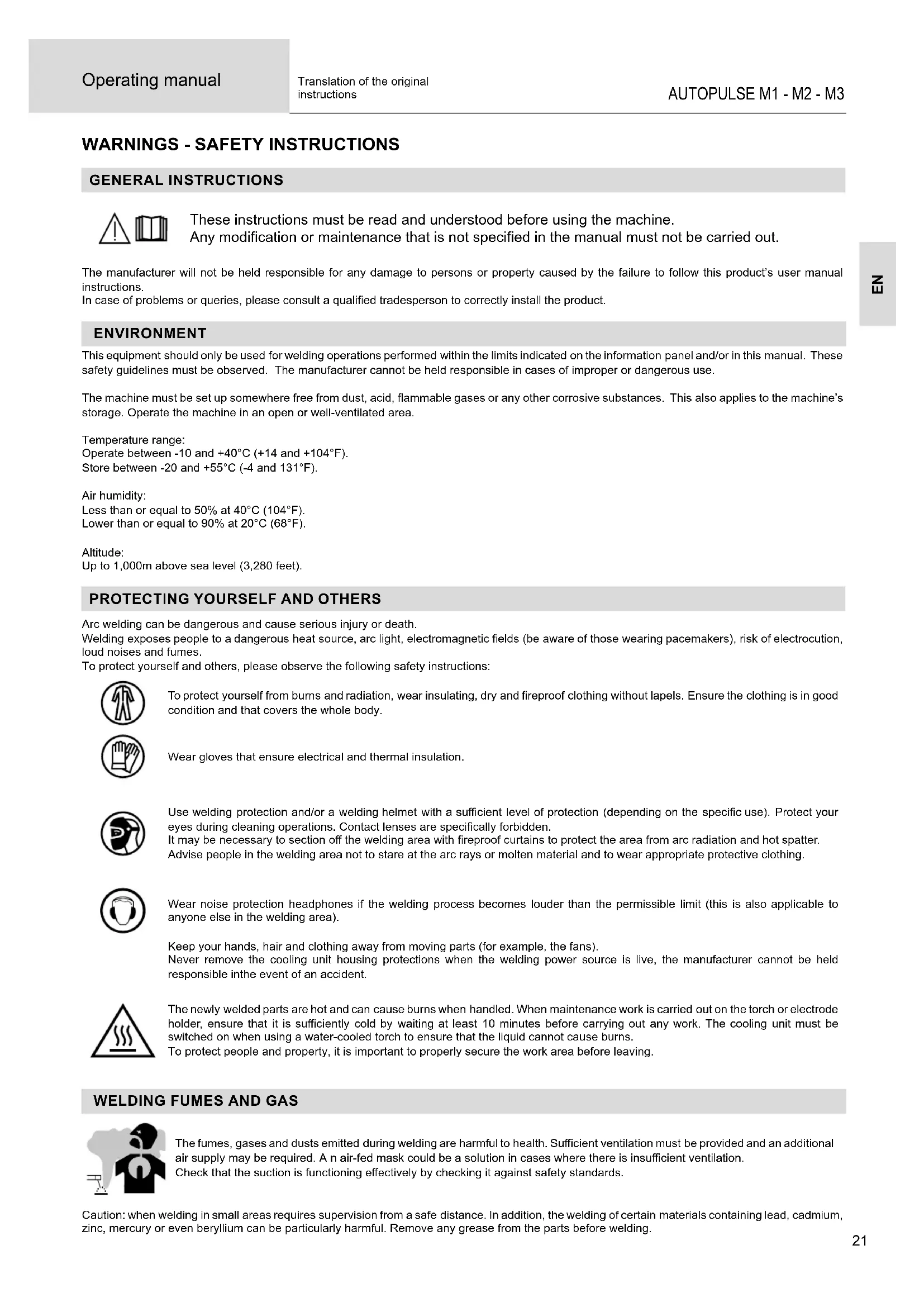
These instructions must be read and understood before using the machine. Any modification or maintenance that is not specified in the manual must not be carried out.
The manufacturer will not be held responsible for any damage to persons or property caused by the failure to follow this product's user manual instructions.
In case of problems or queries, please consult a qualified tradesperson to correctly install the product.
ENVIRONMENT
This equipment should only be used for welding operations performed within the limits indicated on the information panel and/or in this manual. These safety guidelines must be observed. The manufacturer cannot be held responsible in cases of improper or dangerous use.
The machine must be set up somewhere free from dust, acid, flammable gases or any other corrosive substances. This also applies to the machine's storage. Operate the machine in an open or well-ventilated area.
Temperature range:
Operate between -10 and +40°C (+14 and +104°F).
Store between -20 and +55°C (-4 and 131°F).
Air humidity:
Less than or equal to 50% at 40°C (104°F).
Lower than or equal to 90% at 20°C (68°F).
Altitude:
Up to 1,000m above sea level (3,280 feet).
PROTECTING YOURSELF AND OTHERS
Arc welding can be dangerous and cause serious injury or death.
Welding exposes people to a dangerous heat source, arc light, electromagnetic fields (be aware of those wearing pacemakers), risk of electrocution, loud noises and fumes.
To protect yourself and others, please observe the following safety instructions:

To protect yourself from burns and radiation, wear insulating, dry and fireproof clothing without lapels. Ensure the clothing is in good condition and that covers the whole body.

Wear gloves that ensure electrical and thermal insulation.

Use welding protection and/or a welding helmet with a sufficient level of protection (depending on the specific use). Protect your eyes during cleaning operations. Contact lenses are specifically forbidden.
It may be necessary to section off the welding area with fireproof curtains to protect the area from arc radiation and hot spatter. Advise people in the welding area not to stare at the arc rays or molten material and to wear appropriate protective clothing.

Wear noise protection headphones if the welding process becomes louder than the permissible limit (this is also applicable to anyone else in the welding area).
Keep your hands, hair and clothing away from moving parts (for example, the fans).
Never remove the cooling unit housing protections when the welding power source is live, the manufacturer cannot be held responsible in the event of an accident.
The newly welded parts are hot and can cause burns when handled. When maintenance work is carried out on the torch or electrode holder, ensure that it is sufficiently cold by waiting at least 10 minutes before carrying out any work. The cooling unit must be switched on when using a water-cooled torch to ensure that the liquid cannot cause burns.
To protect people and property, it is important to properly secure the work area before leaving.
WELDING FUMES AND GAS

The fumes, gases and dusts emitted during welding are harmful to health. Sufficient ventilation must be provided and an additional air supply may be required. A n air-fed mask could be a solution in cases where there is insufficient ventilation.
Check that the suction is functioning effectively by checking it against safety standards.
Caution: when welding in small areas requires supervision from a safe distance. In addition, the welding of certain materials containing lead, cadmium, zinc, mercury or even beryllium can be particularly harmful. Remove any grease from the parts before welding.
Gas cylinders should be stored in open or well-ventilated areas. They should be kept in an upright position and kept on a cart or trolley. Welding should not be undertaken near grease or paint.
FIRE AND EXPLOSION RISKS

Fully protect the welding area, flammable materials should be kept at least 11 metres away. Fire fighting equipment should be present in the vicinity of welding operations.
Beware the expulsion of hot spatter or sparks, even through cracks, which can cause fires or explosions.
Keep people, flammable objects and pressurised containers at a safe distance.
Do not weld in closed containers or tubes. If they are open, remove any flammable or explosive materials (oil, fuel, etc.) before welding.
Grinding work must not be directed towards the source of the welding current or towards any flammable materials.
GAS CYLINDERS
Gas escaping from the cylinders can cause suffocation if it becomes concentrated in the welding area (ventilate well).
Transporting the machine must be done safely: gas cylinders must be closed and the welding power source turned off. They should be stored upright and supported to reduce the risk of falling.
Tightly close the bottle between uses. Beware of temperature changes and sun exposure.
The bottle should not come into contact with flames, electric arcs, torches, earth clamps or any other sources of heat.
Keep away from electrical and welding circuits and never weld a pressurised cylinder.
When opening the cylinder valve, keep your head away from the valve and ensure that the gas being used is suitable for the welding process.
ELECTRICAL SAFETY

The electrical network used must be earthed. Use the recommended fuse size chosen from the information table. Electric shocks can cause serious direct and indirect accidents or even death.
Never touch live parts connected to the live current, either inside or outside the power source casing unit (torches, clamps, cables, electrodes), as these items are connected to the welding circuit.
Before opening the welding machine's power source, disconnect it from the mains and wait two minutes to ensure that all the capacitors have fully discharged.
Do not touch the torch or the electrode holder and the earth clamp at the same time.
If the cables or torches become damaged, they must be replaced by a qualified and authorised person. Measure the length of cable according to its use. Always wear dry, good quality clothing to insulate yourself from the welding circuit. Alongside this, wear well-insulated footwear in all working environments.
EMC CLASSIFICATION (230 V VERSION)

This Class A equipment is not intended for domestic use where electrical power is supplied from the low-voltage mains system. Ensuring electromagnetic compatibility may be difficult at these sites due to conducted, as well as radiated, radio frequency interference.
This equipment complies with IEC 61000-3-12.
Provided that the impedance of the low-voltage public electrical network at the common coupling point is less than Zmax = 0.349 Ohms, this equipment complies with IEC 61000-3-11 and can be connected to public low-voltage electrical mains. It is the responsibility of the installer or user of the equipment to ensure, in consultation with the distribution network operator if necessary, that the network impedance complies with the impedance restrictions.
ELECTROMAGNETIC INTERFERENCES
An electric current passing through any conductor produces localised electric and magnetic fields (EMF). The welding current produces an electromagnetic field around the welding circuit and the welding equipment.
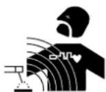
Electromagnetic fields (EMFs) can interfere with some medical devices, for example pacemakers. Protective measures should be taken for those with medical, implanted devices. For example, restricted access for onlookers or an individual risk assessment for welders.
All welders should use the following guidelines to minimise exposure to the welding circuit's electromagnetic fields:
- position the welding cables together - if possible, securing them with a clamp,
- position yourself (head and body) as far away from the welding circuit as possible,
-
never wrap the welding cables around your body,
-
do not position yourself between the welding cables and keep both welding cables on your same side,
- connect the return cable to the workpiece, as close as possible to the area to be welded,
- do not work next to, sit or lean on the source of the welding current,
- do not weld while transporting the source of the welding current or wire feeder.

Pacemaker users should consult a doctor before using this equipment.
Exposure to electromagnetic fields during welding may have other health effects that are not yet known.
RECOMMENDATIONS FOR ASSESSING THE WELDING AREA AND EQUIPMENT
General Information
It is the user's responsibility to install and use the arc welding equipment according to the manufacturer's instructions. If electromagnetic disturbances are detected, it is the user's responsibility to resolve the situation using the manufacturer's technical support. In some cases, this corrective action may be as simple as earthing the welding circuit. In other cases, it may be necessary to construct an electromagnetic shield around the welding current source and around the entire workpiece by setting up input filters. In any case, electromagnetic interference should be reduced until it is no longer an inconvenience.
Assessing the welding area
Before installing arc welding equipment, the user should assess the potential electromagnetic problems in the surrounding area. The following should be taken into account:
a) the presence of power, control, signal and telephone cables above, below and next to the arc welding equipment,
b) radio and television receivers and transmitters,
c) computers and other control equipment,
d) critical safety equipment, e.g. the protection of industrial equipment,
e) the health of nearby persons, e.g. those using of pacemakers or hearing aids,
f) the equipment used for calibrating or measuring,
g) the protection of other surrounding equipment.
The operator has to ensure that the devices and equipment used in the same area are compatible with each other. This may require further protective measures;
h) the time of day when welding or other activities are to take place.
The size of the surrounding area to be taken into account will depend on the building's structure and the other activities taking place there. The surrounding area may extend beyond the boundaries of the premises.
Assessment of the welding equipment
In addition to the assessment of the surrounding area, the arc welding equipment's assessment can be used to identify and resolve cases of interference. It is appropriate that the assessment of any emissions should include in situ procedures as specified in Article 10 of CISPR 11. In situ procedures can also be used to confirm the effectiveness of mitigation measures.
GUIDELINES ON HOW TO REDUCE ELECTROMAGNETIC EMISSIONS
a. The mains power grid: Arc welding equipment should be connected to the mains power grid according to the manufacturer's recommendations. If any interference occurs, it may be necessary to take additional precautionary measures such as filtering the mains power supply. Consider protecting the power cables of permanently installed, arc welding equipment within a metal pipe or a similar casing. The power cable should be protected along its entire length. The protective casing should be connected to the welding machine's power source to ensure good electrical contact between the protective pipeline and the welding machine's power source housing.
b. The maintenance of arc welding equipment: Arc welding equipment should be subject to routine maintenance as recommended by the manufacturer. All access points, service openings and bonnets should be closed and properly locked when the arc welding equipment is in use. The arc welding equipment should not be modified in any way, except for those modifications and adjustments mentioned in the manufacturer's instructions. The spark gap of arc starters and stabilisers should be adjusted and maintained according to the manufacturer's recommendations.
c. Welding cables: Cables should be as short as possible, placed close together either near or on the ground.
d. Equipotential bonding: Consideration should be given to the joining of all metal objects in the surrounding area. However, metal objects connected to the workpiece increase the risk of electric shocks to the user if they touch both these metal parts and the electrode. The user should be isolated from such metal objects.
e. Earthing the workpiece: In cases where the part to be welded is unearthed for electrical safety reasons or due to its size and location, such as ship hulls or structural steel buildings, an earthed connection can reduce emissions in some cases, although not always. Care should be taken to avoid the earthing of parts which could increase the risk of injury to users or damage to other electrical equipment. If necessary, the workpiece's connection should be earthed directly, but in some countries where a direct connection is not allowed, the connection should be made with a suitable capacitor chosen according to national regulations.
f. Protection and protective casing: The selective protection and encasing of other cables and equipment in the surrounding area may limit interference problems. The safeguarding of the entire welding area may be considered for special applications.
THE TRANSPORTING AND MOVING OF THE MACHINE'S POWER SOURCE
Do not use the cables or torch to move the welding power source. It should be transported in an upright position. Do not carry or transport the power source overhead of people or objects.
Never lift a gas cylinder and the welding power source at the same time. Their transport requirements are different. It is advisable to remove the wire spool before lifting or transporting the welding power source.
SETTING UP THE EQUIPMENT
- Place the welding power source on a floor with a maximum inclination of 10^ .
- Provide sufficient space to ventilate the welding power source and access the controls.
- Do not use in an area with conductive metal dust.
- The welding power source should be protected from heavy rain and not exposed to direct sunlight.
• The machine protection level is IP21, which means : - Protection against access to dangerous parts from solid bodies of a ≥12.5mm diameter and,
- Protection against vertically falling drops.

Stray welding currents can destroy earthing conductors, damage electrical equipment and devices and cause component parts to overheat leading to fires.
- All welding connections must be firmly secured and regularly checked!
- Make sure that the item's attachment is firm and secure, without any electrical problems!
- Join together or suspend any electrically conductive parts of the welding source such as the frame, trolley and lifting systems so that they are insulated!
- Do not place other equipment such as drills or grinding devices etc. on the welding source, trolley, or lifting systems unless they are insulated!
- Always place welding torches or electrode holders on an insulated surface when not in use!
Power cables, extension cables and welding cables should be fully unwound to avoid overheating.

The manufacturer assumes no responsibility for damage to persons or objects caused by improper and dangerous use of this equipment.
MAINTENANCE / RECOMMENDATIONS


- Maintenance should only be carried out by a qualified person. Annual maintenance is recommended.
- Switch off the power supply by pulling the plug and wait two minutes before working on the equipment.. Inside the macine, the voltages and currents are high and dangerous.
- Regularly remove the cover and blow out any dust. Take advantage of the opportunity to have the electrical connections checked with an insulated tool by a qualified professional.
- Regularly check the condition of the power cord. If the power cable is damaged, it must be replaced by the manufacturer, the after sales service team or an equally qualified person to avoid any danger.
- Leave the welding power source vents free for air intake and outflow.
- Do not use this welding power source for thawing pipes, recharging batteries/storage batteries or starter motors.
INSTALLATION - USING THE PRODUCT
Only experienced persons, authorised by the manufacturer, may carry out the installation. During installation, ensure that the power source is disconnected from the mains. Series or parallel power source connections are not allowed. It is recommended to use the welding cables supplied with the unit in order to obtain the best performance.
DESCRIPTION
The AUTOPULSE is a «synergic» semi-automatic welding machine, ventilated for welding (MIG or MAG). This machine is recommended for welding steel, stainless steel, aluminium and the brazing. Its adjustment is quick and easy with its «synergic» mode.
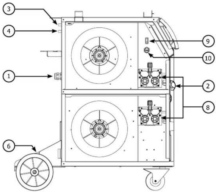
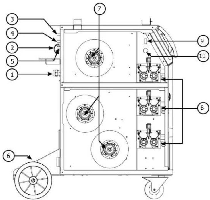
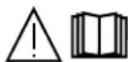
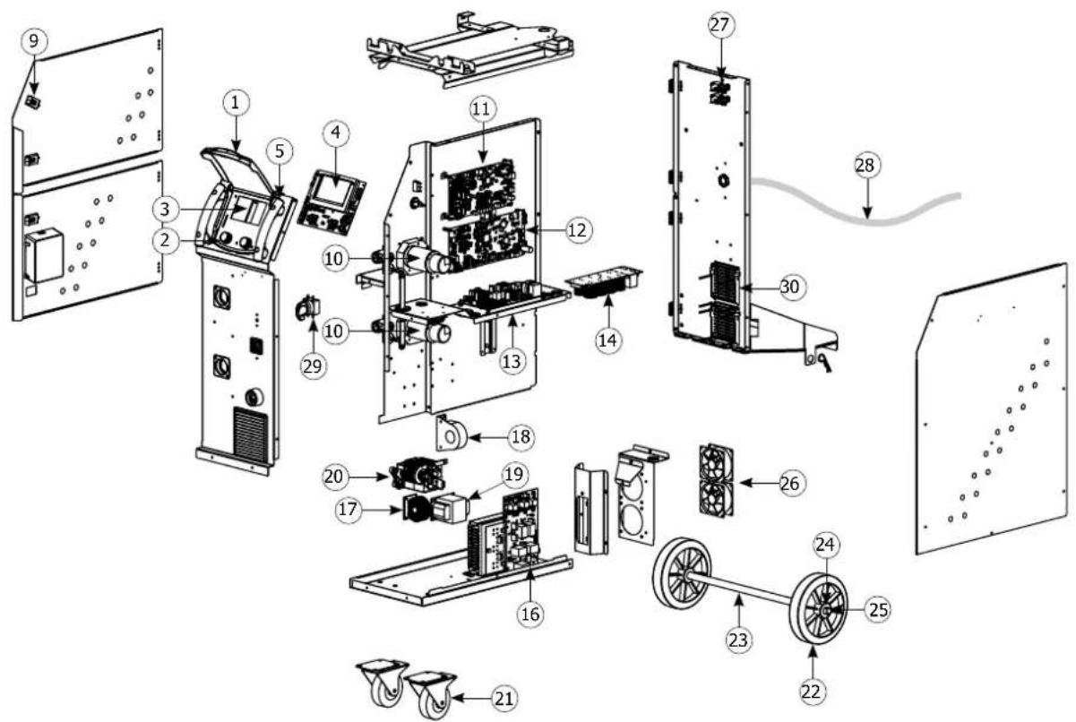
DESCRIPTION OF THE EQUIPMENT (I)
1- Cable gland (mains cable) 9- Switch for purge-gas and wire feeding
2- On/Off switch 10- USB connector
3- Gas connector T1 11- MMI
4- Gas connector T2 12- Push Pull (PP) connector
5- Gas connector T3 13- Texas connector (-)
6- Cylinders support 14- Euro connector T1
7- Reel supports 1, 2 et 3 15- Euro connector T2
8- Wire feeder motor 16- Euro connector T3
HUMAN-MACHINE INTERFACE (HMI)

HMI
Please read the Human Machine Interface (HMI) which forms part of the equipment's user literature.
POWER SWITCH
- The 230V model is fitted with a 16A socket type CEE7/7 which must be connected to a single-phase 230V (50 - 60 Hz) power supply fitted with three wires and one earthed neutral.
- The 208/240V model is supplied without a plug and should only be connected on a single-phase 208-240V (50-60 Hz) three-wire (50-60 Hz) electrical system with a earthed neutral.
The absorbed effective current (I1eff) is displayed on the machine, for optimal use. Check that the power supply and its protection (fuse and/or circuit breaker) are compatible with the current needed by the machine. In some countries, it may be necessary to change the plug to allow the use at maximum settings.
• The machine is designed to work on a 230V -20% +15% power supply. It switches to protection mode if the power supply voltage is below 185V RMS or over 265V RMS. (a default code will appear on the screen display). - Power up the machine by switching the on / off switch (2 - FIG 1) to the I position, and stop it by switching it to the 0 position.
Warning! Never disconnect the power supply while the machine is charging.
CONNECTING TO A POWER SOURCE
The machine can work with generators as long as the auxiliary power matches these requirements:
- The voltage must be AC, always superior to 230 V -20% +15%, and the peak voltage below 400V,
- The frequency must be between 50 and 60 Hz.
It is imperative to check these requirements as several generators generate high voltage peaks that can damage these machines.
USING EXTENSION LEADS
All extension leads must be of a suitable length and width that is appropriate to the equipment's voltage. Use an extension lead that complies with national safety regulations.
| Current input Extension lead section (<45m) | |
| 230 V | 2.5 mm ^2 |
| 208/240 V | 4 mm ^2 (AWG 12) |
SETTING UP THE REEL
text_image
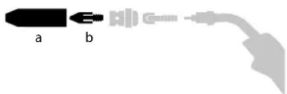
a b- Remove the nozzle (a) and contact tube (b) from your MIG/MAG torch.
text_image
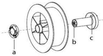
a b cOpen the power source's hatch.
- Position the reel on its holder.
- Take into consideration the reel stands's drive lug (c). To fit a 200 mm reel, tighten the plastic reel holder (a) to the maximum.
- Adjust the brake wheel (b) to prevent the non-moving spool from tangling the wire when the welding stops. In general, do not overtighten, as this will cause the motor to overheat.
LOADING THE FILLER WIRE
natural_image
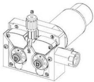
Technical diagram of a mechanical assembly with labeled components (a, b) and mounting holes (S), no readable text or symbols beyond labels.To change the rollers, do the following:
- Loosen the knobs (a) to the maximum and lower them.
- Unlock the rollers by loosening the retaining screws (b).
- Insert the correct motor rollers for your application and tighten the retaining screws.
The rollers supplied are double groove rollers:
- alu ∅ 1.0/1.2 (M1 + M2 + M3)
- steel ∅ 0.8/1.0 (M2 + M3)
- steel ∅ 0.6/0.8 (M3)
natural_image
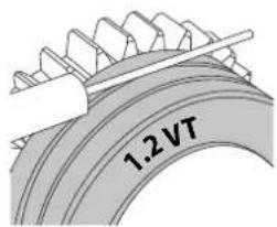
Pure diagram of a vertical cylindrical structure with directional arrows indicating flow or movement (no text or symbols)- Check the inscription on the roller to ensure that the rollers are suitable for the wire diameter and the wire material (for a ∅ 1.2 wire, use the ∅ 1.2 groove).
- Use V-grooved rollers for steel and other hard wires.
- Use U-grooved rollers for aluminium and other soft, alloyed wires.
: visible inscription on the roller (example: 1.2 VT)
→ : groove to use
text_image
1.2 VT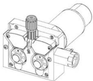
natural_image
Technical line drawing of a mechanical assembly with gears and housing (no text or symbols)Do the following to install the filler wire:
- Loosen the dials to the maximum and lower them.
- Insert the wire, then close the motor reel and tighten the dials as shown.
- Operate the motor using the torch trigger or the manual wire feed button (I-9).

Notes:
- Too narrow a sheath can lead to unreeling issues and can lead to the overheating of the motor.
- The torch connection must also be properly tightened to prevent it from overheating.
- Ensure that neither the wire, nor the reel, touches the device's mechanism, otherwise there is a danger of short-circuiting the machine.
RISK OF INJURY FROM MOVING COMPONENTS

The reels have moving parts that can trap hands, hair, clothing or tools causing injuries!
- Do not touch rotating, moving or driving parts of the machine!
- Ensure that the housing covers or protective covers remain fully closed when in operation!
- Do not wear gloves when threading the filler wire or changing the filler wire reel.
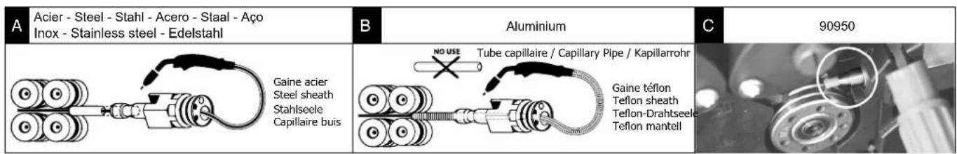
SEMI-AUTOMATIC STEEL/STAINLESS STEEL WELDING (MAG MODE)
AUTOPULSE can weld steel wire from ∅ 0.6 to 1.2 mm and stainless steel from ∅ 0.8 to 1.2 mm (II-A).
The device is supplied as standard with rollers ∅ 0.6/0.8 and ∅ 0.8/1.0 for steel or stainless steel. The contact tube, the roller groove, the torch sheath are designed for this application.
Welding steel requires a specific gas (Ar+CO2). The proportion of CO2 may vary depending on the gas used. For stainless steel, use a mixture with 2% CO2. When welding with pure CO2, it is necessary to connect a gas preheating device to the gas cylinder. For specific gas requirements, please enquire with your gas distributor. The gas flow rate for steel is between 8 and 15 litres / minute depending on the environment. Synergies in Pulse mode are optimized for a gas flow between 12 and 15 liters / minute. To measure the gas flow at the flare outlet, you can use the optional flowmeter (ref. 053939).
SEMI-AUTOMATIC ALUMINIUM WELDING (MIG MODE)
AUTOPULSE can weld aluminium wire from ∅ 0.8 to 1.2 mm (II-B).
Aluminium use requires a specific pure argon gas (Ar). For specific gas requirements, please enquire with your gas distributor. The aluminium gas flow rate is between 15 and 20 l/min depending on the environment and the welder's experience. Synergies in Pulse mode are optimized for a gas flow between 12 and 15 liters / minute.
The differences between using the unit on steel or aluminum are:
- Use specific drive rolls for aluminium welding.
- Apply minimum pressure on the pressure rollers of the motor-driven reel to avoid crushing the wire.
- Use the capillary tube (designed to guide the wire between the drive rolls in the motor and the EURO connector) only for steel/stainless steel welding (II-B).
- Use a torch designed for aluminium. This aluminium torch is fitted with a teflon torch liner in order to reduce frictions. DO NOT cut the liner at the edge of the fitting! This liner guides the wire from the drive rolls.
- Contact tube: use a SPECIAL aluminium contact tube corresponding to the diameter of the wire.
When using red or blue sheathing (aluminium welding), it is recommended to use the 90950 (II-C) accessory. This stainless steel sheath guide improves the centering of the sheath and facilitates the flow of the wire.

Video
SEMI-AUTOMATIC WELDING IN CUSI AND CUAL (SOLDERING MODE)
The machine can weld CuSi and CuAl wire from ∅ 0.8 to 1.2 mm.
In the same way as with steel, a capillary tube must be set up and a torch with a steel sheath must be used. When braze welding, pure argon (Ar) should be used.
GAS SUPPLY
- Fit a suitable pressure regulator to the gas cylinder. Connect it to the welding station with the pipe supplied. Attach the two hose clamps to prevent leaks.
- Ensure that the gas cylinder is held securely in place with a chain attached to the power source.
- Set the gas flow rate by adjusting the dial on the pressure regulator.
NB: To adjust the gas flow rate more easily, use the rollers on the motorised spool by pulling the trigger on the torch (loosen the brake wheel on the motorised reel so that no wire is drawn in). Maximum gas pressure: 0.5 MPa (5 bar).
This procedure does not apply to welding in «No Gas» mode.
MIG / MAG (GMAW/FCAW) WELDING MODE
| Welding processes | ||||||
| Settings | ADJUSTABLE SETTINGS | MANUAL | STD DYNAMIC | PULSE | COLD PULSE | |
| Couple material/gas | - Fe Ar 25% CO _2 - ... | - | ✓ | ✓ | ✓ | Choice of the material to be welded.Pre-installed welding user settings |
| Wire diameter ∅ 0.6 | > ∅ 1.2 mm - Choice of wire | diameter | ✓ | ✓ | ||
| ModulArc | OFF - ON | - | - | ✓ | ✓ | Activating or deactivating the welding current's modulation (Double Pulse) |
| USING THE TRIG-GER | 2T, 4T Choice of trigger welding management mode. | |||||
| Spot welding mode | SPOT, DELAY | ✓ | ✓ | - | - | Selecting spot welding mode |
| First Setting | Thickness Start-up Speed | - | ✓ | ✓ | ✓ | Choosing the main setting to be displayed (thickness of the workpiece, average welding current or wire speed). |
| Power | Hold Thermal coefficient | ✓ | ✓ | ✓ | ✓ | See «Power» section on the following pages. |
Access to some welding settings depends on the selected display mode: Settings/Display mode: Easy, Expert, Advanced. Refer to the HMI manual.
WELDING PROCESSES
For more information on GYS pre-installed user settings and welding processes, scan the QR code:

SPOT WELDING MODE
- SPOT WELDING
This welding mode allows the pre-assembly of parts before welding. Spot welding can be done manually using the trigger or timed with a predefined spot welding period. This spot welding makes reproduction and execution of non-oxidised weld points easier (accessible in the advanced menu).
• TIME LIMITS
This is a welding mode similar to SPOT welding but with predefined weld and dwell times, as long as the trigger is held down.
CONFIGURING THE SETTINGS
| Units | ||
| Wire speed | m/min | Amount of filler metal deposited and consequently the welding intensity and penetration. |
| Voltage V Control over the cord's width. | ||
| Self - Lessens the welding current more or less. To be set according to the welding position. | ||
| Pre-Gas s When the torch is bled and the gas shield is created before ignition. | ||
| Post-Gas s | Duration of the gas protection after the arc is extinguished. It protects the workpiece and the electrode from oxidation. | |
| Thickness mm | The pre-installed user settings (synergies) allow for a fully-automatic set-up. Working with different thicknesses automatically sets the appropriate thread tension and speed. | |
| Start-up A | The welding current is set according to the type of wire used and the material to be welded. | |
| Arc length | - | Used to adjust the distance between the end of the wire and the weld pool (tension adjustment). |
| Approach speed | % | Progressive yarn speed. Before priming, the wire moves slowly to create the first contact without jolting. |
| Hot Start | % & s | The Hot Start is an overcurrent used at the start that prevents the wire from sticking to the workpiece. The intensity (% of welding current) and the time (seconds) can be programmed. |
| Crater Filler | % | This idling bearing current is a phase after the current is lowered. The intensity (% of welding current) and the time (seconds) can be programmed. |
| Soft Start s | Gradual current increase. The current is controlled between the first contact and the welding process in order to avoid the possibility of violent ignitions or jolts. | |
| Uplsope | s Upslope current | |
| Cold current | % | Second welding current known as a «cold» welding current. |
| Pulse frequency | Hz | Pulse frequency |
| Duty cycle | % | In pulsed mode, the hot current time is adjusted in relation to the cold current time. |
| Downslope | s Downslope current. | |
| Tack welding | s Set duration. | |
| Time between two points | s | Time between the end of a point (excluding Post-Gas) and the start of a new point (including Pre-Gas). |
| Burnback | s | Feature preventing the thread sticking to the bead. This is timed to coincide with the wire rising from the weld pool. |
Access to some welding settings depends on the welding process (Manual, Standard, etc.) and the selected display mode (Easy, Expert or Advanced). Refer to the HMI manual.
MIG/MAG WELDING CYCLES
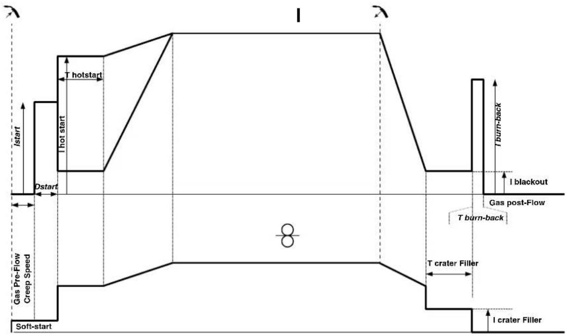
Standard 2T process:
text_image
Istart I hot start T hotstart Dstart Gas Pre-Flow Creep Speed Soft-start I crash Filler I crater Filler I burn-back I blackout T burn-back T crater Filler Gas post-FlowWhen the trigger is pulled, the pre-gas starts. When the wire touches the workpiece, a pulse initiates the arc and the welding cycle starts. When the trigger is released, the wire feeding stops and a current pulse cleanly cuts the wire, followed by the post-gas. As long as the post-gas has not finished, pressing the trigger will allow a quick restart of the weld (manual chain stitch) without going through the HotStart phase. A HotStart and/or a crater filler can be added to the cycle.
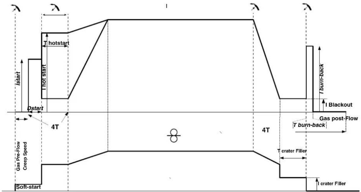
Standard 4T process:
text_image
I start Hot start I start Dstart 4T Gas Pre-Flow Creep Speed Soft-start I hotstart I hot start I burn-back I Blackout T burn-back Gas post-Flow T crater Filler I crater FillerIn a standard 4T process, the timing of pre-gas and post-gas is managed automatically. HotStart and crater filler are both controlled by the trigger.
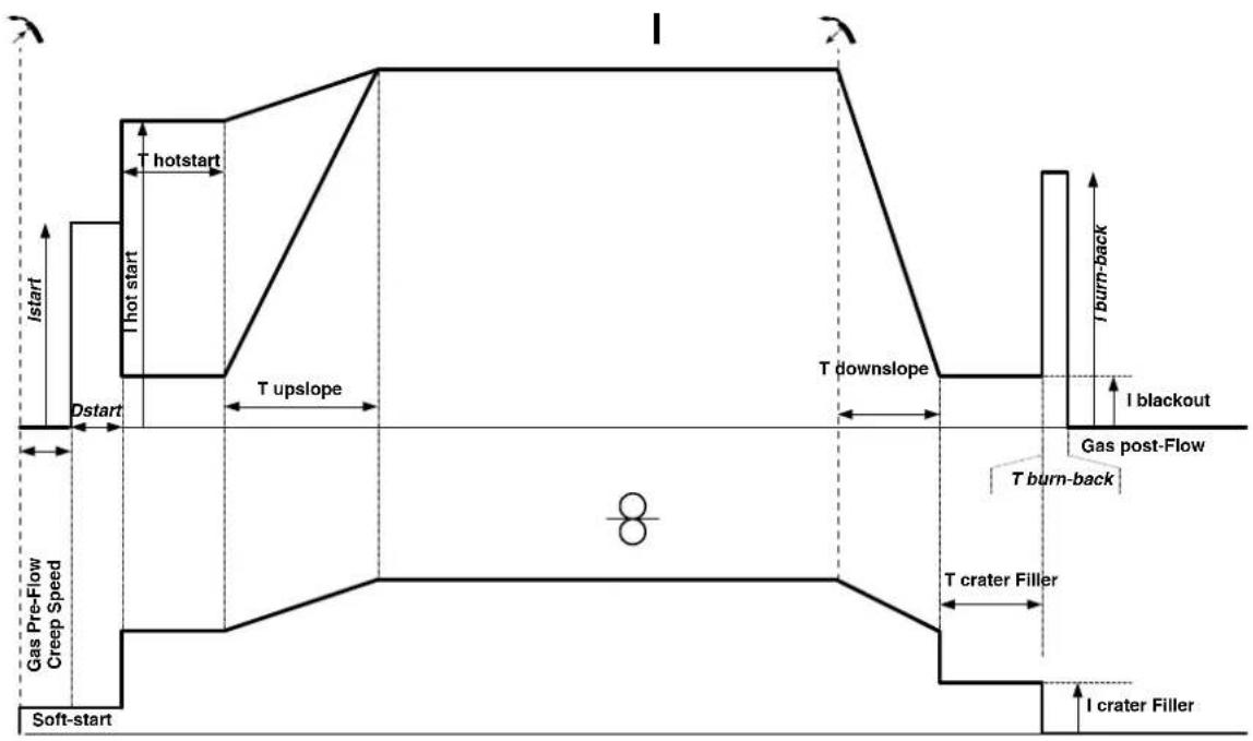
Pulsed 2T process:
text_image
I hotstart I start I hot start Dstart T upslope T downslope I burn-back I blackout Gas pre-Flow Creep Speed T burn-back T crater Filler I crater Filler Soft-startWhen the trigger is pulled, the pre-gas starts. When the wire touches the workpiece, a pulse initiates the arc. Then, the machine starts with HotStart or upslope and finally, the welding cycle starts. When the trigger is released, the downslope initiates until it reaches crater fill. Then the STOP PEAK cuts the wire followed by the Post gas. Just as in Standard mode, the user can quickly restart the welding process during the post-gas phase without going through the HotStart phase.
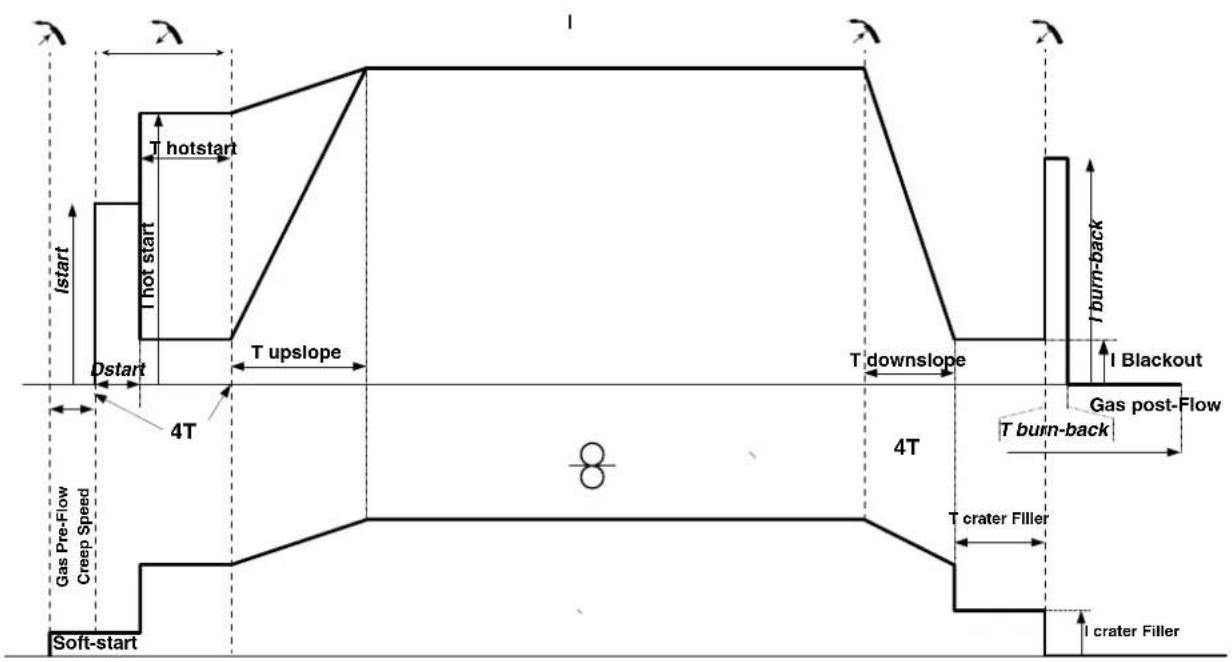
Pulsed 4T process:
text_image
I hotstart I start I hot start Dstart T upslope 4T Gas Pre-Flow Creep Speed Soft-start I Crater Filler T Crater Filler T upslope T downslope I Blackout T burn-back Gas post-Flow T burn-back I Crater FillerIn pulsed 4T mode, the timing of the pre-gas and post-gas is managed automatically. HotStart and crater fill are controlled by the trigger.
POWER
A method developed for welding with DMOS-regulated energy control. As well as displaying the energy of the weld bead after welding, this mode allows the setting of the thermal coefficient according to the standard used: One for ASME standards and 0.6 (TIG) or 0.8 (MMA/MIG-MAG) for European standards. The energy displayed is calculated taking into account this coefficient.
OPTIONAL PUSH-PULL TORCH
| Reference number | Wire diameter Length Cooling type | |
| 044111 0.6 > | 1.0 mm 4 m Air | |
| 046283 0.6 > | 1.2 mm 4 m Air |
A push-pull torch can be connected to the power source via the socket (I-13). This type of torch allows the use of AlSi wire even in 0.8 mm with a torch length of 8 m. This torch can be used in all MIG-MAG welding modes.
The Push-Pull torch is detected by simply pulling the trigger.
When using a push-pull torch with potentiometer, the highest control range setting can be set using the interface.
The potentiometer can then range anywhere between 50% and 100% within this setting.
DEFECTS: CAUSES & SOLUTIONS
| SYMPTOMS POSSIBLE CAUSES SOLUTIONS | ||
| The flow of the welding wire is not constant. | Clogs blocking the opening. | Clean the contact tube or replace it with non-stick material. |
| The wire slips in the roller. Reapply the non-stick product. | ||
| One of the rollers is spinning. Check the tightness of the roller screw. | ||
| The torch cable is twisted. | The torch cable should be as straight as possible. | |
| The reel motor is not working. Reel brake or roller is too tight. Loosen the brake and rollers. | ||
| Incorrect wire unwinding. | Dirty or damaged wire guide. Clean or replace. | |
| Roller pin key is missing. Reposition the pin in its slot. | ||
| Reel brake is too tight. Loosen the brake. | ||
| No current or wrong welding current. | Improper connection of mains plug. | Check the plug connection and verify that the plug is connected to the power supply. |
| Poor earth connection. | Check the earthing cable (its connection and the condition of the clamp). | |
| No power. | Check the torch trigger. | |
| The wire jams after passing through the rollers. | Crushed wire guide sheath. | Check the sheath and torch. |
| Wire jamming in the torch. | Replace or clean. | |
| No capillary tube. | Check that the capillary tube is present. | |
| Wire speed too high. | Reduce the wire speed. | |
| The weld bead is porous. | The gas flow is insufficient. | Adjustment range from 15 to 20 L / min.Clean the base metal. |
| Gas cylinder empty. | Replace it. | |
| Unsatisfactory gas quality. | Replace it. | |
| Air circulation or wind influence. | Avoid draughts and protect the welding area. | |
| Gas nozzle is too clogged. | Clean or replace gas nozzle. | |
| Bad wire quality. | Use a wire suitable for MIG/MAG welding. | |
| Condition of the welding surface is too poor (rusted, etc.). | Clean the workpiece before welding. | |
| The gas is not connected. | Check that the gas is connected to the power source's inlet. | |
| Excessive sparks. | Arc voltage is too low or too high. | See welding settings. |
| Poor earth connection. | Check and position the earth clamp as close as possible to the area to be welded. | |
| Insufficient gas protection. | Adjust the gas flow. | |
| No gas coming from the torch. | Poor gas connection. | Check the connections of gas inlets. |
| Check that the solenoid valve is working. | ||
| Error while downloading. | The data on the USB stick is incorrect or corrupted. | Check your data. |
| Backup error. | You have exceeded the maximum number of backups. | You need to delete some programs.The number of backups is limited to 500. |
| Automatic deletion of JOBS. | Some of your JOBs have been deleted because they were incompatible with the new pre-installed user settings (synergies). | - |
| Push Pull torch detection error. - Check Push Pull | torch connection. | |
| USB key error. | There is no JOB detected on the USB stick. - | |
| The product's memory space is full. Free up some space on the USB key. | ||
| File error. | The file does not match the pre-installed user settings (synergies) downloaded to the product. | The file was created with pre-installed user settings (synergies) that are not present on the machine. |
WARRANTY CONDITIONS
The warranty covers any defects or manufacturing faults for two years from the date of purchase (parts and labour).
The warranty does not cover:
- Any other damage caused by transportation.
- General wear of parts (eg.: cables, clamps, etc.).
- Damage caused by misuse (incorrect power supply, the dropping or dismantling of equipment).
- Environmental failures (pollution, rust and dust).
In the event of a breakdown, return the appliance to your distributor, together with:
- dated proof of purchase (receipt, invoice, etc.),
- a note explaining the breakdown..
natural_image
Technical line drawing of a mechanical assembly with labeled components (a, b) and mounting holes (S), no readable text or symbols beyond labels.natural_image
Pure diagram of a vertical cylindrical structure with directional arrows indicating flow or movement (no text or symbols)natural_image
Technical line drawing of a mechanical assembly with gears and housing (no text or symbols)text_image
Istart Dstart Gas Pre-Flow Creep Speed Soft-start I hot start T hotstart I hot start I burn-back I blackout T burn-back T crater Filler I crater Fillertext_image
I start J hotstart Hot start Dstart 4T Gas Pre-Flow Creep Speed Soft-start I Crater Filler T crater Filler 4T I burn-back I Blackout Gas post-Flow T burn-backtext_image
I hotstart I start I hot start Dstart T upslope T downslope I burn-back I blackout Gas pre-flow Creep Speed T burn-back T crater Filler I crater Filler Soft-starttext_image
I start I hot start T hotstart Dstart T upslope 4T Gas Pre-Flow Creep Speed Soft-start I Crater Filler T crater Filler T upslope T downslope I Blackout T burn-back Gas post-Flow T burn-backnatural_image
Technical diagram of a mechanical assembly with labeled parts (a, b) and mounting holes (S), no readable text or symbols beyond labels.natural_image
Pure diagram of a vertical cylindrical structure with directional arrows indicating flow or movement (no text or symbols)natural_image
Technical line drawing of a mechanical assembly with no visible text or symbolstext_image
I start I hot start T hotstart D start Gas Pre-Flow Creep Speed Soft-start I crash Filler I crater Filler T crater Filler T burn-back Gas post-Flow I blackouttext_image
I start I hot start I start Dstart 4T Gas Pre-Flow Creep Speed Soft-start I hot start I hot start I burn-back I Blackout Gas post-Flow T burn-back T crater Filler I crater Fillertext_image
Istart I hot start hotstart Dstart Gas Pre-Flow Creep Speed Soft-start T upslope T downslope I burn-back I blackout Gas post-Flow T burn-back T crater Filler I crater Fillertext_image
I start I hot start I hot start Dstart T upslope 4T Gas Pre-Flow Creep Speed Soft-start I Crater Filler T crater Filler T downslope I Blackout T burn-back T burn-back Gas post-Flownatural_image
Technical diagram of a mechanical assembly with labeled components (a, b), no readable text or symbols present.natural_image
Pure diagram of a vertical cylindrical structure with directional arrows indicating flow or movement (no text or symbols)natural_image
Technical line drawing of a mechanical assembly with no visible text or symbolstext_image
I start I hot start T hotstart Dstart Gas Pre-Flow Creep Speed Soft-start I burn-back I blackout T burn-back T crater Filler I crater Fillertext_image
Istart Hotstart I start Hot start Dstart 4T Gas Pre-Flow Creep Speed Soft-start I Crater Filler I Crater Filler T Crater Filler 4T T burn-back I Blackout T burn-back Gas post-Flowtext_image
I hotstart I start I hot start Dstart T upslope T downslope I burn-back I blackout Gas pre-Flow Creep Speed T burn-back T crater Filler I crater Filler Soft-starttext_image
I hotstart I start I hot start Dstart T upslope 4T Gas Pre-Flow Creep Speed Soft-start I Crater Filler T Crater Filler T upslope T downslope I Blackout T burn-back Gas post-Flow T burn-backWAARSCHUWINGEN - VEILIGHEIDSINSTRUCTIES
ALGEMENE INSTRUCTIES
INTERFACE HUMAN - MACHINE (IHM)

MMI
natural_image
Technical line drawing of a mechanical assembly with labeled components (a, b, d), no readable text or symbols present.natural_image
Pure diagram of a vertical cylindrical structure with directional arrows indicating flow or movement (no text or symbols)natural_image
Technical line drawing of a mechanical assembly with gears and housing (no text or symbols)text_image
I start I hot start T hotstart Dstart Gas Pre-Flow Creep Speed Soft-start I burn-back I blackout T burn-back T crater Filler I crater Fillertext_image
Istart Dstart 4T Gas Pre-Flow Creep Speed Soft-start I hot start I hot start I burn-back I Blackout Gas post-Flow T burn-back T crater Filler I crater Fillertext_image
I hotstart I start I hot start Dstart T upslope T downslope I burn-back I blackout Gas pre-flow Creep Speed T burn-back T crater Filler I crater Filler Soft-starttext_image
I start I hot start T hotstart Dstart T upslope 4T Gas Pre-Flow Creep Speed Soft-start T upslope T downslope I Blackout T burn-back Gas post-Flow T burn-back T crater Filler I crater Fillernatural_image
Technical diagram of a mechanical assembly with labeled parts (a, b) and mounting holes (S), no readable text or symbols beyond labels.natural_image
Pure diagram of a vertical cylindrical structure with directional arrows indicating flow or movement (no text or symbols)natural_image
Technical line drawing of a mechanical assembly with no visible text or symbolstext_image
I start I hot start T hotstart Dstart Gas Pre-Flow Creep Speed Soft-start I burn-back I blackout T burn-back T crater Filler I crater Fillertext_image
Istart I hot start I hot start Dstart 4T Gas Pre-Flow Creep Speed Soft-start I Crater Filler I Crater Filler I burn-back I Blackout T burn-back Gas post-Flow T crater Fillertext_image
I I start I hot start T hotstart Dstart T upslope T downslope I burn-back I blackout Gas pre-Flow Creep Speed T crater Filler I crater Filler Soft-starttext_image
I hotstart I start Hot start Dstart 4T T upslope T downslope I Blackout Gas pre-Flow Creep Speed Soft-start T crater Filler I crater Filler T burn-back T burn-back T downslope I burn-backtext_image
Exploded view diagram of a mechanical or electronic device with numbered components and labeled partsAUTOPULSE M2
text_image
Exploded view diagram of an electronic device with numbered components and labeled partsAUTOPULSE M3
text_image
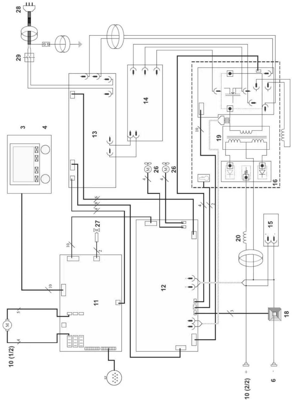
Exploded view diagram of a computer system with numbered components for identification and assembly.| AUTOPULSE | |||||||
| M1230 V | M1208/240 V | M2230 V | M2208/240 V | M3230 V | M3208/240 V | ||
| 1 | Carter plastique / Plastic housing / Kunststofffgehäuse / Contenitore plastico | 56199 | |||||
| 2 | Bouton noir 28mm / Button black 28mm / Knopf schwarz 28mm / Tasto nero 28mm | 73016 | |||||
| 3 Clavier / Keyboard / Tastatur / Tastiera 51973 | |||||||
| 4 Circuit IHM / MMI circuit / HMI-Schaltung / 97466C | |||||||
| 5 | Poignée plastique / Plastic handle / Kunststoffgriff / Circuito IHM(interfaccia) | 56047 | |||||
| 6 | Embase texas / Texas base / texanische Basis / Impugnatura plastica | 51461 | |||||
| 7 | Grille plastique 120x120 / Plastic grid 120x120 / Kunststoffgitter 120x120 / Griglia in plastica 120x120 | 51010 | |||||
| 8 | Charnière / Hinge / Scharnier / Cerniera | 56239 | |||||
| 9 Verrou / Lock / Lock / bloccare 71003 | |||||||
| 10 | Moto dévidoir 24V 50W / 24V 50W reel / 24V 50W Spule / Bobina moto 24V 50W | 51141 | |||||
| 11 | Circuit dévidoir / Reel circuit / Haspelschaltung / Circuito trainafilo | E0056C E0116C * | 97808C | ||||
| 12 | Circuit contrôle / Control circuit / Steuerstromkreis / Circuito di controllo | 97482C | |||||
| 13 | Circuit alimentation / Power supply circuit / Stromversorgungsschaltung / Circuto alimentazione | 97781C | |||||
| 14 | Circuit condensateurs / Capacitor circuit / Kondensatorschaltung / Circuito condensatori | 97479C | |||||
* Si fabrication / If manufacturing < 11/2021 = ref 97497C
* Si fabrication / If manufacturing ≥ 11/2021 = ref 97808C
| 15 | Circuit CEM / EMC circuit / EMV-Schaltung / Scheda CEM | 97369C | |||||
| 16 | Module puissance complet / Complete power module / Komplettes Leistungsmodul / Modulo di piena potenza | 97555 | |||||
| 17 Self PFC / PFC Self 64673 | |||||||
| 18 | Capteur de courant 500A / Current sensor 500A / Stromsensor 500A / Sensore di corrente 500A | 64460 | |||||
| 19 | Transformateur de puissance / Power transformer / Leistungstransformator / Trasformatore di potenza | 96138 | |||||
| 20 Self de sortie / Output Self / Self di uscita 96143 | |||||||
| 21 | Roue avant / Front wheel / Vorderrad / Ruote anteriori | 71360 | |||||
| 22 | Roue arrière / Rear wheel / Hinterrad / Ruote posteriori | 71375 | |||||
| 23 | Axe de roue / Wheel axle / Radachse / Rondella piatta | 91059ST 98908ST | 98908ST | ||||
| 24 | Rondelle plate / Flat washer / Unterlegscheibe / Ventilatore | 41214 | |||||
| 25 | Goupille / Pin / Stift / Perno | 42032 | |||||
| 26 Ventilateur / Ventilator / Ventilator / Ventilatore 50999 | |||||||
| 27 | Electrovanne / Solenoid valve / Magnetventil / Elettrovalvola | 71542 | |||||
| 28 | Cordon secteur / Power cord / Netzkabel / Cavo corrente | 21496INDX | F0000 | 21496INDX | F0000 | 21496INDX | F0000 |
| 29 | Interrupteur marche/arrêt / On/off switch / Ein/Aus-Schalter / Interruttore avvio/stop | 51075 | |||||
| 30 | Grille plastique 92x92 / Plastic grid 92x92 / Kunststoffgitter 92x92 / Griglia plastica 92x92 | 51011 | |||||
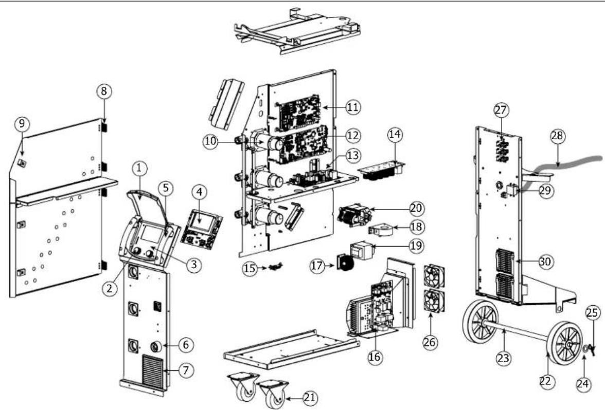
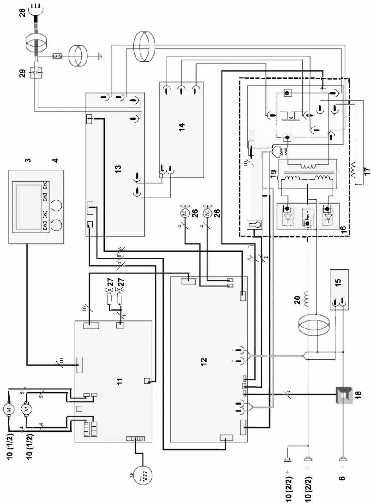
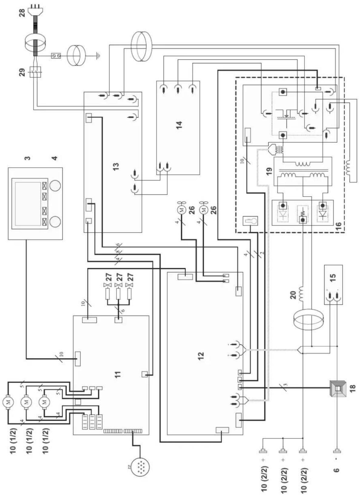
CIRCUIT DIAGRAM / SCHALTPLAN / DIAGRAMA ELECTRICO / ЭЛЕКТРИЧЕСКАЯ СХЕМА / ELEKTRISCHE SCHEMA / SCEMA ELETTRICO
AUTOPULSE M1 - 230 V + 208-240 V
flowchart
graph TD
    A["10 (1/2)"] --> B["5"]
    B --> C["4"]
    C --> D["11"]
    D --> E["12"]
    E --> F["13"]
    F --> G["14"]
    G --> H["15"]
    H --> I["16"]
    I --> J["19"]
    J --> K["20"]
    K --> L["18"]
    L --> M["6"]
    M --> N["10 (2/2)"]
    N --> O["+"]
    O --> P["3"]
    P --> Q["27"]
    Q --> R["4"]
    R --> S["26"]
    S --> T["19"]
    T --> U["10"]
    U --> V["29"]
    V --> W["28"]
    W --> X["3"]
    X --> Y["4"]
AUTOPULSE M2 - 230 V + 208-240 V
flowchart
graph TD
    A["10 (1/2)"] --> B["M"]
    C["10 (1/2)"] --> D["M"]
    B --> E["11"]
    D --> F["11"]
    E --> G["12"]
    F --> H["12"]
    G --> I["13"]
    H --> J["13"]
    I --> K["14"]
    J --> L["14"]
    K --> M["15"]
    L --> N["16"]
    M --> O["17"]
    N --> P["18"]
    O --> Q["19"]
    P --> R["20"]
    Q --> S["21"]
    R --> T["22"]
    S --> U["23"]
    T --> V["24"]
    U --> W["25"]
    V --> X["26"]
    W --> Y["27"]
    X --> Z["28"]
    Y --> AA["29"]
    Z --> AB["30"]
AUTOPULSE M3 - 230 V + 208-240 V
flowchart
graph TD
    A["28"] --> B["29"]
    B --> C["3"]
    C --> D["4"]
    D --> E["10 (1/2)"]
    D --> F["10 (1/2)"]
    D --> G["10 (1/2)"]
    D --> H["11"]
    H --> I["12"]
    I --> J["13"]
    J --> K["14"]
    K --> L["15"]
    L --> M["16"]
    M --> N["17"]
    N --> O["18"]
    O --> P["19"]
    P --> Q["20"]
    Q --> R["21"]
    R --> S["22"]
    S --> T["23"]
    T --> U["24"]
    U --> V["25"]
    V --> W["26"]
    W --> X["27"]
    X --> Y["28"]
    Y --> Z["Output 18"]
    style A fill:#f9f,stroke:#333
    style Z fill:#ccf,stroke:#333
Identification - Options ON
This interface (HMI) manual forms part of the complete documentation. A general manual is included with the product. Read and follow the general manual's instructions, particularly the safety instructions!
Only for use with the following products:
AUTOPULSE

Version du logiciel
This user manual describes the following software versions: 1.86. The software's version can be found on the main menu: Information / MMI
Using the device
The main screen contains all the necessary information for the entire welding process, including the pre-, mid- and post-welding phases (the interface may change slightly depending on the selected process).
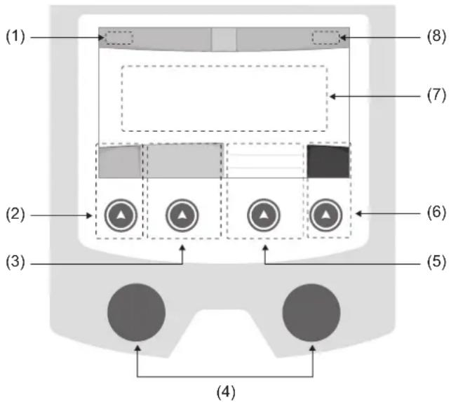
The main menu screen is displayed when the product is first started.
Navigating between the different sections is done using the dials and buttons.
flowchart
graph TD
    A["Parameters System Locking"] --> B["Users Traceability Portability"]
    C["✓"] --> D["End"]
    style A fill:#f9f,stroke:#333
    style B fill:#ccf,stroke:#333
    style C fill:#cfc,stroke:#333
    style D fill:#fcc,stroke:#333
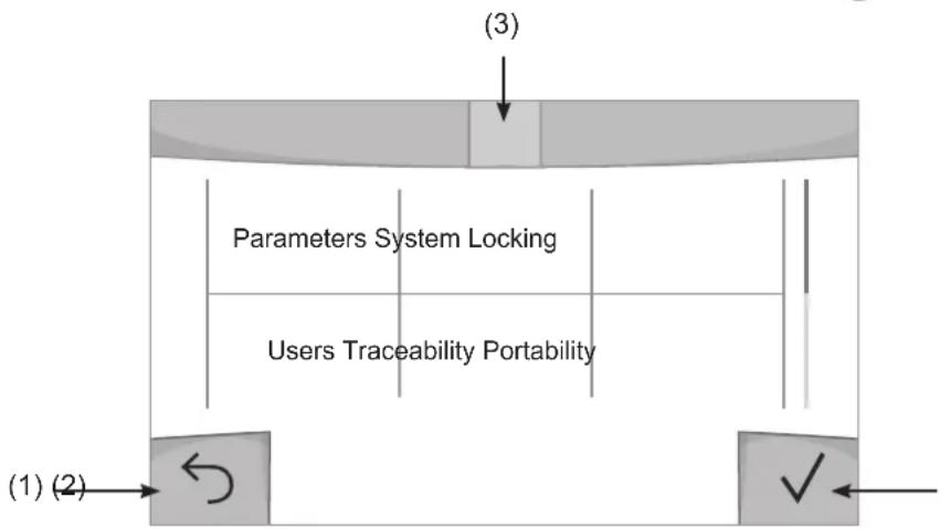
(1) Back
(2) Validation
(3) The current section's computer icon
Settings (User settings)
Display mode
- Easy: reduced display and functionality (no access to the welding cycle).
- Expert: full display, allows the user to adjust the timing of the different welding cycle phases.
- Advanced: full display, allows the user to adjust all the welding cycle settings.
Language
Choice of the interface language (English, French, German, etc).
Units of measurement
Choice of measurement units: International (SI) or Imperial (USA).
Material naming
European standard (EN) or American standard (AWS).
Brightness
Adjusts the interface screen's brightness (setting from 1 [very dark] to 10 [very bright]).
User Code
Customise the user's access code to safely lock the machine (default 0000).
Tolerance I (current)
Current tolerance control:
OFF : Freely adjustable, the current setting is not limited.
± 0A : no tolerance, current limitation.
± 1A> ± 50A : The setting range at which the user can adjust their current.
Tolerance U (voltage)
Voltage tolerance control:
OFF : freely adjustable, the voltage setting is not limited.
± 0.0V : no tolerance, voltage limiting.
± 0.1V> ± 5.0V : setting range at which the user can vary the voltage.
Tolerance 8(wire speed)
Wire speed setting tolerance (m/min):
OFF : freely adjustable, wire speed setting is not limited.
± 0.0m/min : no tolerance, wire speed control.
± 0.1m/min> ± 5.0m/min : setting range at which the user can vary the wire speed.
Using the machine's System
Naming Device Interface
Information about the device's name and the option to customise it can be reached by pressing on the interface.
Clock
Setting the time, date and format (AM/PM).
Reset
Pressing 'Reset' will reset the machine's settings:
- Partial: will reset the default value of the present welding process.
- Total: Will reset all the device's configuration data to the factory settings.
Locking
This machine's interface screen can be locked to protect any work in progress and prevent unintentional or accidental changes.
The current settings window can still be modified with the settings chosen in the Settings menu (see previous page). All other functions are inaccessible.
To unlock the interface, press push button #1 and enter your 4-digit user code (default 0000).
Users
The user mode enables the machine to be shared between several users. The first time that the machine is started, it will be in Admin mode. The administrator can create user profiles. Each user has his own setup (mode, setting, process and JOBs etc.) and this cannot be modified by another user. Each user needs a personal four-digit code in order to sign in to the machine.
- The administrator has access to the entire general menu.
- Users have access to a simplified interface. Users do not have the ability to delete information (Tracking, Jobs, User profiles, etc).
User configuration interface (reserved for the administrator).
The left side of the screen lists the users. The administrator has the ability to sort these users by name or by date by quickly pressing button n°2. Pressing this button for a prolonged time will delete the active user(s) instead (although the Admin account cannot be deleted).
On the right side of the screen, you can see the details of all the users previously created with the following information: Avatar, Name, Team No. and Tolerance (%).
Creating a user profile
Press button n°3 to create a new user.
- User : Customise the user's name by pressing push button n°3.
- Avatar : Choice of avatar colour
- Team : Assignment of the team number (10 max)
- User code : personal access code (default 0000)
- Current setting tolerance I:
OFF : freely adjustable, the current setting is not limited.
± 0.0A : no tolerance, limiting the current (not recommended).
± 0.A> ± 50A : Setting interval at which the user can vary their current.
- Voltage setting tolerance U:
OFF : freely adjustable, the voltage setting is not limited.
± 0.0V : no tolerance, limiting the voltage (not recommended).
± 0.1V> ± 5.0V : setting range at which the user can vary the voltage.
- Wire speed setting tolerance (m/min)
OFF : freely adjustable, the wire speed setting is not limited.
± 0.0m/min : no tolerance, limiting the wire speed (not recommended).
± 0.1m/min > ± 5.0m/min : the range of settings at which the user can vary the wire speed.
It is not possible to change the admin name or avatar for the «Admin» user.
Changing a user profile
Select the user on the left side of the screen and press the push button n°4.
Selecting users
If one or more user profiles are created, the user block displays all of the machine's users.
Select the user of your choice and press √ to confirm the choice. You will be asked for an unlock code.
The «Close» feature locks the machine on the user's choice so that no other settings are accessible. This screen remains the same when the machine is switched on (OFF -> ON switch).
User display
The active avatar and username are displayed at the top left of the screen.
Unlocking code
Each user profile is protected by a personal, four-digit code. The default code will be 0000 if not changed. After failing to correctly enter your personal code three times, the interface will be blocked and you will be asked for an unlock code. This code is made up of six digits and cannot be changed. It is: 314159.
Using the machine's Tracking interface
This welding management interface allows you to track/record every step of the welding operation, bead by bead, during any industrial operation. This quality-driven approach ensures high post-production welding quality through analysis, evaluation, reporting and documentation of the recorded welding settings. This feature allows for the accurate and fast collection and storage of data required under EN ISO 3834. This data can be recovered and exported to a USB stick.
1- Start - Creating a tracking system
- Personalise the site's name by pressing push button n°3.
- Sampling interval :
- Hold : No recording of current/voltage values (average along the wire) during welding.
- 250 ms, 500 ms, etc.: Recording of the current/voltage values (average along the wire) every «X» milliseconds or seconds during welding.
- Options - OFF : simple tracking
- Options - ON : full tracking
Pass counter (ON/OFF)
Weld counter (ON/OFF)
Temperature (ON/OFF): Temperature of the part to be welded at the beginning of the weld bead.
Length (ON/OFF) : Length of the wire (units of measurement are displayed according to the choices made in Settings/Units of Measurement).
Variable(s): allows you to add additional personalised information (weight, notes, wire speed, etc.).
Press √ to start tracking.
Tracking display
At the top left of the screen, the job name and the bead number are displayed (the bead number goes up automatically and cannot be changed).
Identification - Options ON
At the end of each bead, an identification window appears: Pass N°, Weld N°, Part temperature and/or Bead length.
Validation
Confirmation can be done on the HMI or by pressing the torch's trigger.
Stop - Stop tracking
To stop tracking during a welding process, the user must return to the Tracking block and select «Stop».
Export
The recovery of this information is done by exporting the data to a USB stick.
The CSV data can be processed with a spreadsheet program (Microsoft Excel®, Calc OpenOffice®, etc).
The file name is linked to the machine name and serial number.
2- Start - Tracking management
The left-hand side of the screen lists previously created work sites.
The user has the possibility to sort these worksites by name or by date by quickly pressing button n°2. Holding down this button will delete the active job or all jobs.
The right-hand side of the screen shows the details of each of the previously created jobs with the following information: sampling frequency, number of recorded welds, total welding time, welding energy supplied, setup of each weld (process, timestamp, welding time and welding U-I).

Rec
Creation of a tracking system (see previous paragraph)
Start the active site's tracking system
Portability
Import Setup.
Upload the machine settings from a USB memory stick (directory: Removable Disk\PORTABILITY\CONFIG) to the machine. Press and hold to delete the settings on the USB stick.
Export Configuration
Export the machine settings to a USB stick (directory: Removable Disk\PORTABILITY\CONFIG)
Import Job
Importing Jobs to the machine according to the processes available in the USB key's Removable Disk directory.
Export Job
Exporting jobs from the machine to a USB stick according to the processes (directory: Removable Disk\PORTABILITY\JOB). Caution, older jobs on the USB stick may be deleted.
To prevent data loss during data import or export, do not remove the USB flash drive or turn off the machine. The file name is linked to the machine name and serial number.
Calibration
Calib. Speed
Feature designed to calibrate the speed of the motorised reel. The purpose of calibration is to compensate for variations in reel speed in order to adjust the displayed voltage measurement and to refine the energy calculations.
The procedure, once started, is explained with an animation on the screen.
Calibration of the motorised reel speed must be done regularly to ensure optimal welding.
Information
Setup data of the product's system components:
- Model
- Serial number
- Device name
- Software version
- Job and Synergies (preinstalled user settings) used.
Pressing any push button will exit the information screen.
Job memories and reminders
Can be accessed via the «JOB» icon on the main screen.
The settings in use are automatically saved and remembered the next time you turn on the machine.
In addition to the current settings, it is possible to save and remember so-called «JOB» settings.
There are 500 JOBS for the MIG/MAG process. Data storage is based on the current process settings, the current settings and the user profile.
Job
This JOB mode enables JOBs to be created, saved, remembered and deleted.
Quick-Load – Recall JOBs from the trigger when not welding.
Quick Load is a non-welding JOB recall mode (20 max) and only possible in MIG-MAG process.
From a list of previously created JOBs, JOB recalls are done by short trigger presses. All trigger modes and welding modes are supported.
Error codes
The following table shows a non-exhaustive list of messages and error codes that may appear. Carry out these checks and controls before contacting an authorised GYS technician.

If the user needs to open the product, they must turn off the power supply by unplugging the electrical plug and waiting two minutes for safety.
| Error codes | Messages Solutions | |
| 001 | OVER VOLTAGE FAULTCheck the electrical installation | Have your electrical installation checked by an authorised person. |
| 002 | UNDERVOLTAGE FAULTCheck the electrical installation | |
| 005 Earth current fault. | There is a stray current. Check the wiring of the welding accessory (torch, earth clamp, electrode holder, etc.) | |
| 010 | GENERATORThermal protection | Wait a few minutes for the power source to cool down.Ensure that the recommended duty cycle for the welding current used is not exceeded. Thermal protection Ensure that the air inlets and outlets are not obstructed. |
| 011 | FanFan fault | Fan Switch off the power supply by unplugging the electrical plug and check the fan. Ensure that the fan is not blocked. |
| 012 | TRIGGERThe trigger is pressed. | Remove the torch and check that the message is still applicableCheck that the «Gas purge / Wire feed» switch is not obstructed or stuck.Check that the MIG/MAG torch trigger is not obstructed or stuck. |
| 015 | MOTORUnable to reach the required speed | Check the pressure settings of the motorised reel rollers.Check that the filler wire is not blocked in the torch sheath.If it is Impossible to reach the requested speed, calibrate the speed of the motorised wire reels (Menu «Calibration»). |
| 019 | If overloaded, please check your settings.Release the trigger to clear | Check the power source's settings and the machine's installation (filler wire, rollers, etc.)If the problem persists, carry out an update (Via Planet GYS). |
| 020 | Welding start problemPlease check your welding parametersPress and release the trigger to clear. | Check the power source's settings and the machine's installation (filler wire, rollers, etc.)If the problem persists, carry out an update (Via Planet GYS). |
| 024 | USB overloadUnplug your USB. | Change the USB stick. |
| - | An internal system error has occurred.Please restart your machine | Restart your machine by turning the machine off and on again.If the problem persists, carry out update (via Planet GYS) |
| - Error during motor calibration Recalibrate the motor reel speed (Menu «Calibration») | ||
| - Error during calibration Recalibrate the welding cables (Menu «Calibration») | ||
| - No more memory space in the machine Delete Jobs to free up the internal storage space. | ||
| - | Unsupported files %sErr %dContinue anyway? | The data on the USB stick is corrupted. |
| - Unable to save to the USB stick | Free up space on the USB stick.If the problem persists, change the USB stick. | |
| - | Number of attempts exceeded.Unlock code required | Enter unlock code: 314159 |
| - | Wrong user code | Wrong user code If the personal code is wrong, enter the correct code.By default, this code is 0000. |
If an unlisted error code appears or your problems persist, contact GYS Customer Service.
Warning icons
The alert icons at the top right of the screen provide you with more information about your product.
| Warning Meaning | |
 | Alert meaning the machine is in Demonstration mode.Check your electrical installation (mains voltage). |
| [boer7] | End-of-life interface battery. Change the battery (CR2032) and update the [product's date and time (System / Clock). |
| [boer1] | The fan is not running at the right speed. Check the fan's condition. |