
ZIRMM94H_230V - Industrial machine Zipper - Free user manual and instructions
Find the device manual for free ZIRMM94H_230V Zipper in PDF.
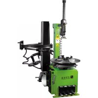
| Product type | Industrial machine: tire changer |
| Brand | Zipper |
| Model | ZI-RMM94H_230V |
| Supply voltage | 230 V |
| Required air pressure | 8 to 10 bar |
| Maximum inflation pressure | 3.5 bar (50 PSI) |
| Mounting head | High-quality aluminum |
| Clamping system | 4 jaws with cylinders, automatic centering |
| Bead breaker | Adjustable |
| Main functions | Mounting, dismounting and inflation of tires |
| Periodic maintenance | Daily cleaning, monthly lubrication, check oil level and belt tension |
| Cleaning | With mild detergent, avoid solvents and corrosive products |
| Safety | Mandatory grounding, hearing and eye protection, do not exceed 3.5 bar |
| Spare parts | Use only genuine Zipper parts |
| Warranty | 2 years for non-professional use, 1 year for industrial use |
| EAN number | 9120039230313 |
Frequently Asked Questions - ZIRMM94H_230V Zipper
User questions about ZIRMM94H_230V Zipper
0 question about this device. Answer the ones you know or ask your own.
Ask a new question about this device
Download the instructions for your Industrial machine in PDF format for free! Find your manual ZIRMM94H_230V - Zipper and take your electronic device back in hand. On this page are published all the documents necessary for the use of your device. ZIRMM94H_230V by Zipper.
USER MANUAL ZIRMM94H_230V Zipper
12.1 Intended use of the machine 21
12.1.1 Technical Restrictions 21
12.1.2 Prohibited Use/Forseeable Misuse 21
12.2 User Requirements 21
12.3 General Safety Instructions 21
12.4 Electrical Safety 22
12.5 Special Safety Instructions for ZI-RMM94H 22
12.6 Hazard warnings 23
13 TRANSPORT 23
14 ASSEMBLY 23
14.1 Checking Scope of Supply 23
14.2 The workplace 24
14.1 Electrical connection 24
14.2 Compressed air connection 24
14.3 Operating test 24
15 OPERATING 24
15.1 Operation 26
15.1.1 Clamp swivel arm and mounting rail 26
15.1.2 Mounting auxiliary arm lifting / lowering 26
15.1.3 Pull the trigger tire from the rim 26
15.1.4 Remove tire from the rim 26
15.2Frosting rim 27
15.3 Inflate the tires 27
16 CLEANING, MAINTENANCE, STORGE, DISPOSAL 28
16.1 Cleaning 28
16.2 Maintenance 28
16.2.1 Maintenance schedule 28
16.2.1 Checking the lubricating oil level 28
16.2.2 Antriebsriemenspannung prufen 28
16.3 Storage 28
16.4 Disposal 29
17 TROUBLESHOOTING 29
18 PRÉFACE (FR) 30
19 SECURITE 31
EN READ THE MANUAL! Read the user and maintenance manual carefully and get familiar with the controls in order to use the machine correctly and to avoid injuries and machine defects.
EN CRUSH HAZARD - KEEP HANDS OFF TURNING PLATE AND MOUNTING HEAD DURING OPERATION
FR RISQUE D'ECRASEMENT !- GARDER LES MAINS ET Toute AUTRE PARTIES DU CORP ELOIGNÉ DDU PLATEAU TOURNANT ET DE LA TÉTE DE MONTAGE DURANT LE FONCTIONNEMENT DE LA MACHINE
IT PERICOLO DI SCHIACCIAMENTO! - TENERE LE MANI LONTANE DAL TAVOLOROTANTE E DALLA TESTA DI MONTAGGIO DURANTE L'uso!
DE QUETSCHUNGSGEFAHR! - HÄNDE UND ANDERE KÖRPERTEILE WÄHREND DEM BETRIEB VON DEN KLEMMZYLINDERN FERNHALTEN!
EN CRUSH HAZARD - KEEP HANDS AND OTHER BODY PARTS OFF CLAMPING CYLINDERS DURING OPERATION
FR RISQUE D'ÉCRASEMENT! - GARDER LES MAINS ET LES AUTRES PARTIES DU CORPS ÉLOIGNÉES DES CYLINDRES DE SERRAGE PENDANT LE FONCTIONNEMENT
IT PERICOLO DI SCHIACCIAMENTO! - TENERE LE MANI E LE ALTRE PARTI DEL CORPO LONTANE DAI CILINDRI DI SERRAGGIO DURANTE L'USO!
DE QUETSCHUNGSGEFAHR! - HANDE UND ANDERE KORPERTEILE WAHREND DEM BETRIEB NIE ZWISCHEN KLEMMBACKEN UND REIFEN HALTEN!
EN CRUSH HAZARD - KEEP HANDS AND OTHER BODY PARTS OFF CLAMPING SHOES AND TYRE!
FR RISQUE D'ÉCRASEMENT! - GARDEZ LES MAINS ET LES AUTRES PARTIES DU CORPS ÉLOIGNÉES DES MORS ET ROUE!
IT PERICOLO DI SCHIACCIAMENTO! - TENERE LE MANI E LE ALTRE PARTI DEL CORPO LONTANE DALLE GANASCE E DAGLI PNEUMATICI DURANTE L'uso!
Use proper safety clothing and devices when operating the machine (safety gloves, safety goggles, ear protectors, safety shoes ...)!
FR
Warning of electrical voltage
FR
Explosion Hazard! Never exceed 3.5 bar (50PSI) while seating beads or inflating. Read and observe the instruction manual
FR
This manual contains information and important instructions for the installation and correct use of the ZIPPER tyre changer ZI-RMM94H.
Following the usual commercial name of the machine (see cover) is substituted in this manual with the name "machine".

This manual is part of the product and shall not be stored separately from the product. Save it for later reference and if you let other people use the product, add this instruction manual to the product.
Please read and obey the security instructions!
Due to constant advancements in product design, construction pictures and content may diverse slightly. However, if you discover any errors, inform us please.
Technical specifications are subject to changes!
Please check the product contents immediately after receipt for any eventual transport damage or missing parts.
Claims from transport damage or missing parts must be placed immediately after initial product receipt and unpacking before putting the product into operation.
Please understand that later claims cannot be accepted anymore.
Copyright
2018
This document is protected by international copyright law. Any unauthorized duplication, translation or use of pictures, illustrations or text of this manual will be pursued by law. Court of jurisdiction is the regional court Linz or the competent court for 4707 Schlüsslberg, Austria!
Customer service contact
This section contains information and important notices for safe commissioning and handling of machine.

For your own safety, read these operating instructions carefully before putting the machine into operation. This will enable you to handle the machine safely and prevent misunderstandings as well as possible damage to property and persons. Also observe the symbols and pictograms used as well as the safety instructions and hazard warnings!
12.1 Intended use of the machine
The machine is intended exclusively for the following activities:
With the ZIPPER tyre changer ZI-RMM94H tires can be mounted, dismantled and inflated on rims.
ZIPPER-MASCHINEN assumes no responsibility or warranty for any other use or use beyond this and for any resulting damage to property or injury.
12.1.1 Technical Restrictions
The machine is intended for use under the following ambient conditions:
Relative humidity: max. 70%
Temperature (for operation) +5irc C bis +40irc C
Temperature (for storage and/or transport) -20ircC bis +55ircC
12.1.2 Prohibited Use / Forseeable Misuse
Operation of the machine without adequate physical and mental aptitude
- Operating the machine without appropriate knowledge of the operating instructions
Changes in the design of the machine
- Operating the machine outdoors.
- Operating the machine in a potentially explosive environment
Operation of the machine without functioning or missing guards
- Remove the safety markings attached to the machine.
- Modify, circumvent or disable the safety devices of the machine.
.
The prohibited/hazardous use or disregard of the information and instructions presented in this manual will result in the voiding of all warranty and damage claims against Zipper Maschinen GmbH.
12.2 User Requirements
The physical and mental suitability as well as knowledge and understanding of the operating instructions are prerequisites for operating the machine. Persons who, because of their physical, sensory or mental abilities or their inexperience or ignorance, are unable to operate the machinery safely must not use it without the supervision or instruction by a responsible person. Please note that local laws and regulations may determine the minimum age of the operator and restrict the use of this machine!
Put on your personal protective equipment before working on the machine.
Work on electrical components or equipment may only be carried out by a qualified electrician or carried out under the guidance and supervision of a qualified Electrician.
12.3 General Safety Instructions
To avoid malfunctions, damage and health hazards when working with the machine, in addition to the general rules for safe working, the following points must be observed:
Before commissioning, check the machine for completeness and function.
-
Choose a level, vibration-free, non-slip surface for the installation location.
-
Ensure sufficient space around the machine!
-
Ensure sufficient lighting conditions at the workplace to avoid stroboscopic effects!
-
Only use perfect tools that are free of cracks and other defects (e.g. deformations).
-
Remove setting tools from the machine before switching on.
-
Keep the area around the machine free of obstacles (e.g. dust, chips, cut workpiece parts etc.).
-
Check the strength of the machine connections before each use.
-
Never leave the running machine unattended. If necessary, stop the machine before leaving.
The machine may only be operated, serviced or repaired by persons who are familiar with it and who have been informed of the dangers arising in the course of this work.
-
Ensure that unauthorised persons maintain an appropriate safety distance from the machine and, in particular, keep children away from the machine..
-
Wear suitable protective equipment (eye protection, dust mask, respiratory protection, ear protection, gloves when handling tools) as well as close-fitting work protective clothing - never wear loose clothing, ties, jewellery, etc. - danger of being drawn in!
-
Work with gloves on rotating parts is not permitted!
-
Hide long hair under hair protection.
-
Do not remove any sections or other parts of the workpiece from the cutting area while the machine is running!
-
Do not remove splinters and chips by hand! Use a sliding stick for this purpose!
Always work with care and the necessary caution and never use excessive force.
-
Do not overload the machine!
-
Do not work on the machine if you are tired, not concentrated or under the influence of medication, alcohol or drugs!
-
Do not use the machine in areas where vapours from paints, solvents or flammable liquids represent a potential danger (danger of fire or explosion!).
-
Do not smoke in the immediate vicinity of the machine (fire hazard)!
-
Make sure that the ON/OFF switch is in the "OFF" position before connecting the machine to the power source.
-
Do not use the machine if it cannot be switched on and off with the ON/OFF switch.
-
Make sure that the device is earthed.
-
Only use suitable extension cords.
-
Always shut down the machine before carrying out any conversion, adjustment, measuring, cleaning, maintenance or repair work and always disconnect it from the power supply for maintenance or repair work. Before starting any work on the machine, wait until all tools or machine parts have come to a complete standstill and secure the machine against unintentional restarting.
12.4 Electrical Safety
- Make sure that the machine is earthed.
- Only use suitable extension cords.
- A damaged or tangled cable increases the risk of electric shock. Handle the cable with care. Never use the cable to carry, pull or disconnect the power tool. Keep the cable away from heat, oil, sharp edges or moving parts.
- Proper plugs and sockets reduce the risk of electric shock.
Water entry into machine increases the risk of electric shock. Do not expose machine to rain or moisture. - The machine may only be used in humid environments if the power source is protected by a residual current circuit breaker.
- Do not use the machine if it cannot be turned on and off with the ON/OFF switch.
12.5 Special Safety Instructions for ZI-RMM94H
- While operating any foot pedal, stay away from the turntable and trigger device!
-
Check for foreign objects in the working area. Put trousers in safety shoes. No loose shoelaces!
-
Serious risk of injury with possible fatal consequences in the event of tire blowouts during the inflation process!
o Therefore NEVER exceed the maximum recommended tire pressure by the tire manufacturer.
o Before inflating check tires and rims for perfect condition.
o During the inflation check condition and pressure again and again
12.6 Hazard warnings
Despite intended use, certain residual risks remain. Due to the design and construction of the machine, hazardous situations may occur which are identified as follows in these operating instructions:
| DANGER | |
| ! | A safety instruction designed in this way indicates an imminently hazardous situation which, if not avoided, will result in death or serious injury. |
| WARNING | |
| ! | Such a safety instruction indicates a potentially hazardous situation which, if not avoided, may result in serious injury or even death. |
| CAUTION | |
| ! | A safety instruction designed in this way indicates a potentially hazardous situation which, if not avoided, may result in minor or moderate injury. |
| NOTICE | |
| ! | A safety note designed in this way indicates a potentially dangerous situation which, if not avoided, may result in property damage. |
Irrespective of all safety regulations, their sound common sense and corresponding technical suitability/training are and remain the most important safety factor in the error-free operation of the machine. Safe working depends first and foremost on you!
13 TRANSPORT
| WARNING | |
| Damaged or insufficiently strong hoists and load slings can result in serious injury or even death. Before use, therefore, check hoists and load slings for adequate load bearing capacity and perfect condition. Secure the loads carefully. Never stand under suspended loads! | |
To ensure proper transport, also observe the instructions and information on the transport packaging regarding centre of gravity, attachment points, weight, means of transport to be used and the prescribed transport position, etc.
Transport the machine in its packaging to the installation site. To manoeuvre the machine in the packaging, use a pallet truck or forklift truck with appropriate lifting capacity. For unproblematic unloading, at least three additional persons are required due to the high weight or the use of a forklift/crane with appropriate lifting gear and qualified personnel for operation.
14 ASSEMBLY
14.1 Checking Scope of Supply
Check the machine immediately after delivery for transport damage and missing parts.
14.2 The workplace
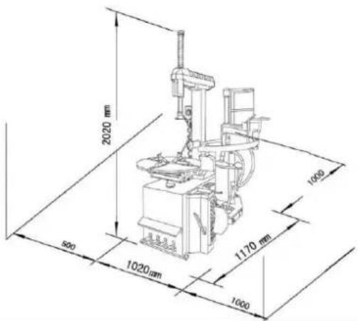
Choose a suitable place for the machine. This shall conform to applicable provisions for job security and have a suitable power and compressed air supply. The ground must be firm and level and can support the weight of the machine.
Provide at least 1m free space around the machine. Attach the machine through the 4-prepared holes on the machine feet to sub-floor.
14.1 Electrical connection
WARNING

When working on an not grounded machine: Serious injury due to electric shock in the event of a malfunction possible!
Therefore the following applies: Machine must be operated at a grounded power socket.
The electrical connection of the machine is ready for operation on a grounded outlet! If a plug is supplied, this must only be connected to a properly fitted and grounded electrical outlet! The plug (if supplied) must not be changed. If this does not fit or is defective, only a qualified electrical engineer may modify or replace the plug!
The grounding conductor is green-yellow! In the event of repair or replacement of the grounding conductor must not be connected to an under voltage can! Check with a qualified electrician or service that the grounding instructions are understood and the machine is grounded!
A damaged cable must be replaced immediately!
14.2 Compressed air connection
Connect the machine with the compressed air connection (24) to your pneumatic device. Please note the ZI-RMM94H must only be connected to a compressed air supply with 8-10 bar.
14.3 Operating test
Check the function of the pedals as well as the compressed air supply. In case of malfunction the respective connections shall be checked again!
15 OPERATING
NOTICE

To avoid damage, use the supplied tire lever for mounting, or dismounting tires.
The area between the tire and rim, in which rests the bead breaker should always be coated for ease of disassembly and protect the rim with lubricant or soapy water.
Take care when mounting the tire on any given course directions on the tire sidewall.
Tire and rim must fit the dimensions forth to each other.
Check the tire always for damage (deformation, surface damage, extreme wear and te before removing the tire.
Always bear in mind any special assembly / disassembly instructions from the tire manufacturer.
If you inflate the tire, make sure that the pressure rise is normal and pay attention to the tire bead.

15.1 Operation
15.1.1 Clamp swivel arm and mounting rail
- Attach the swivel arm by pressing the pedal (3) forward to working position.
- Position the mounting head at the correct distance from the rim.
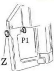
- By pressing the locking button A to position P1, the mounting rail is blocked with mounting head and the swing-arm. The mounting head brings automatically to the correct distance to the rim.
- The locking button A released in the P2 position, the mounting rail and the swing-arm.
15.1.2 Mounting auxiliary arm lifting / lowering
By actuating the control valve B on the mounting sub arm it be raised or lower.

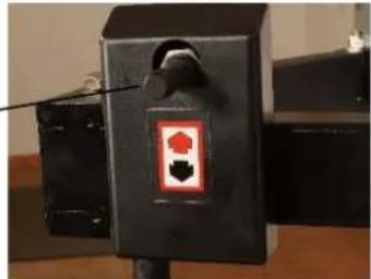
B
15.1.3 Pull the trigger tire from the rim
Let Carefully remove the air from the tire. Remove all foreign objects and weights from the rim.
Lubricate the tire bead lubricantor soapy water, before you squeeze the tire so that you protect the tire bead.
See Figure C:
- Place the tire to the pressure plate (21) so that the bead breaker shoe (20) max. 1cm is just around the rim edge.
ATTENTION: Feet / hands out of the danger zone!
- Activate the control pedal (1), the bead breaker pushes the tire from the rim from.
- Repeat the last steps in several places on the rim until the tire has come off the rim.
15.1.4 Remove tire from the rim
- Place the tire on the turntable (6).
ATTENTION : In asymmetric drop center rims set the tire on so that the flatter side is up. - Do all the way to the outside jaws according to drive the control pedal (2).
Note: There are different types of jaws according to the different fields genotypes. For aluminum rims, you should use the 4 jaw protectors. - In the event that you want to stretch the rim from the inside out, shut the jaws together first, put the tire on the turntable and stand on the pedal (2) to clamp the rim.
- In the event that you want to stretch the rim outside, take the jaws apart (2 -3cm from the edge of the rim away), the tire place centered on the turntable and contact to tension the wheel and pedal (2).
- Depress the control pedal (2), making sure that the 4 jaws (7) Tighten the wheel on the rim flange.
- Press the control pedal (3) and thus the pivot arm in working position, press the mounting rail (11) down so that the mounting head (7) 1-2mm away from the edge of the rim to protect the rim.
- Secure the work position by pressing the locking button A - described in 7.1.1 -
See Figure D:
Pull the outer tire bead with the tire iron over the mounting head.
- With the auxiliary mounting arm (15), you can use the pressing plate (16) or of the press roller (22) the tire bead into the rim to push the tire bead easy to lift over the rim flange.
- Activate the control pedal (4) to rotate the turntable clockwise until the tire was completely drawn over the rim. To prevent damage to a possibly existing hose, position the wheel so that the valve is about 10mm from the mounting head.
Siehe Figure E:
- First, remove the hose, if available.
- Now lift the mounting iron the bottom bead over the mounting head.
- Depress the pedal (4) to solve the lower tire bead and thus the whole tire from the rim.
- Depress the pedal (2) to open the jaws and take the rim from the turntable down.
NOTE: For subsequent mounting of a tire, the rim remains on the turntable.
15.2 Frosting rim
- Check that the tire and rim fit in size to each other!
- Tension. Rim just as when removing the tire If you want to frost the same rim new, let clamped the rim.
- Lubricate the tire bead and the rim edges with a lubricant or soapy water.
- Place the tire on the rim so that the left side is higher and move the pan back into working position.
See Figure F:
- Position the tire so that the tire bead is higher than the left (Fig. 1 F), however, but under the right side (Fig. 2 F) of the mounting head.
- With the auxiliary mounting arm (15) you can push the tire bead into the rim to easily lift the tire bead to the mounting head over the rim flange with the press plate (16) or of the press roller (22).
- Activate the control pedal (4), the inner tire bead is pulled under the outer edge of the rim.
- Insert the inner tube, if available. This should not interfere with the installation!
See Figure G:
Now go for mounting the upper bead the same way as in the lower bead.
NOTE: The bead press roller (22) or tire pressure block (23) is used to facilitate the assembly and disassembly operations. With the standard tires can and must at the UHP tires bead breaker be used
- Press the operating pedal (4) to turn the rotary plate (5) and press the bead breaker roller onto the tyre with the mounting arm.
- If only about 10 - 15cm are left, proceed more carefully to avoid possible damage to the tyre bead. Stop the engine immediately if there is a risk of damaging the tyre and lift the pedal (4) with your foot to turn the turntable back.
- Repeat the process after the tire has regained its original shape.
15.3 Inflate the tires
DANGER

Check and follow the instructions! Non-compliance can lead to serious injury or death! ZIPPER machines cannot be held liable for accidents if safety instructions are not followed!
Double-check the rim and tire size to determine that they match.
Before inflating sure the tire and the rim are undamaged and properly mounted.
NEVER exceed the inflation pressure recommended by the tire pressure.
Inflate the tire in short intervals and check often the pressure of the tire. Check again the tire mold for any abnormalities.
Be careful when tire inflation. Keep hands and other body parts while inflating the tire away!
Connect the supplied filler with pressure gauge reading on the air hose adapter.
Connect the filler to the tire valve. By pressing the push lever, air is pumped into the tire.
16 CLEANING, MAINTENANCE, STORGE, DISPOSAL
16.1 Cleaning
NOTE

Wrong cleaning agents can attack the varnish of the machine. Do not use solvents, nitro thinners, or other cleaning agents that could damage the machine's paint. Observe the information and instructions of the cleaning agent manufacturer!
Prepare the surfaces and coat the bare machine parts with an acid-free lubricating oil. Subsequently, regular cleaning is a prerequisite for the safe operation of the machine and a long service life of the machine. Therefore, clean the machine after each use, but at least once a week.
16.2 Maintenance
WARNING

Handling the machine with the power supply up can lead to serious injuries or even death. Always disconnect the machine from the power supply before servicing or maintenance work and secure it against unintentional or unauthorised reconnection!
The machine is low-maintenance and only a few parts have to be serviced. Nevertheless, malfunctions or defects which could impair the safety of the user must be rectified immediately!
- Before each operation, check that the safety devices are in perfect condition.
- Check the connections for tightness at least once a week.
- Regularly check that the warning and safety labels on the machine are in perfect and legible condition.
- Vent the machine 3-4 times a year.
16.2.1 Maintenance schedule
The type and degree of machine wear depend on the operating conditions. The following intervals apply when the machine is used within the specified limits:
| Intervall | Komponente | Aktivität |
| Before usage | Turntable | clean |
| Before usage | Oil level | Check and refill |
| Before usage | Jaws | Lubriacte |
| 1 x month | Screw connection | Check and re-tighten |
| 1 x month | Moving parts | lubricate |
| 1 x month | Drive belt tension | Check and re-adjust |
16.2.1 Checking the lubricating oil level
Remove the cover from the left side of the tire changer to gain access to the drive belt. To do this, loosen and remove the four fastening screws of the cover and remove it. If the belt is no longer sufficiently tensioned, you can tension it by turning an adjusting screw located on the motor plate.
16.3 Storage
NO TE

Improper storage can damage and destroy important machine parts. Store packed or unpacked parts only under the intended ambient conditions!
Before disconnect the machine from the power supply and disconnect the air supply. Turn off the compressed air supply and release by the filling the remaining pressure from the system before disconnecting the machine at (24) from the compressed air supply.
16.4 Disposal
Observe the national waste disposal regulations. Never dispose of the machine, machine components or equipment in residual waste. If necessary, contact your local authorities for information on the disposal options available. If you buy a new machine or an equivalent device from your specialist retailer, he is obliged in certain countries to dispose of your old machine properly.
17 Troubleshooting
WARNING

Handling the machine with the power supply up can lead to serious injuries or even death. Always disconnect the machine from the power supply before servicing or maintenance work and secure it against unintentional or unauthorised reconnection!
Many possible sources of error can be excluded in advance if the machine is properly connected to the mains. If you are unable to carry out necessary repairs properly and/or do not have the required training, always consult a specialist to correct the problem!
| Trouble | Possible cause | Solution |
| Machine does not start | Emergency stop switch to switch off switch or a phase is broken Overload protection is triggered. Safety fuse is blown Open cover plate for saw blades | Turn the emergency OFF switch to the right to unlock to Repair the defective circuit or the faulty phase Wait until the engine cools down Replace the fuse Cover plate close |
| Burn marks on the workpiece | The blade is blunt | Replace the blade |
| Fence values different from the set value | Ruler incorrectly set | Adjust the ruler correctly |
| The finished size of the machined workpiece is incorrect for the cutting width on rip fence | Adjusted measurement scale for the cutting width display | Setting dimension scale: cut workpiece on the rip fence, measure the workpiece and the measuring scale move so that the measured average width is shown at the edge of the ruler |
| Sliding table at end positions higher than machine table | Lower rollers set incorrectly | Adjust the lower rollers |
| Workpiece clamped while advancing | dull blade Riving knife thickness does not match the used blade | Replace with sharp blade Splitting wedge thickness must be greater than or equal to blade thickness. |
| Broken edges on the workpiece | The scoring saw is not on the same line with the main saw | Set the scoring saw a new |
| Arm running not smoothly | Telescopic tube or track rollers dirty | telescopic tube or track rollers clean Check wipers |
18 PRÉFACE (FR)
Cher client!
(EN) With ZIPPER spare parts you use spare parts that are ideally matched to each other. The fitting accuracy of the parts shortens their installation time and increases the service life of the machine.
NO TE
The installation of parts other than original spare parts leads to the loss of the
guarantee! Therefore, when replacing components/parts, only use original spare parts! When ordering spare parts, please use the service form at the end of this manual. Always state machine type, spare part number and designation. In order to avoid misunderstandings, we recommend enclosing a copy of the spare part drawing with the spare part order, on which the required spare parts are clearly marked.
You will find the ordering address under customer service addresses in the foreword to this documentation.
Company ZIPPER Maschinen GmbH grants for mechanical and electrical components a warranty period of 2 years for amateur use; and warranty period of 1 year for professional use, starting with the purchase of the final consumer. In case of defects during this period, which are not excluded by paragraph 3, ZIPPER will repair or replace the machine at its own discretion.
2.) Report:
In order to check the legitimacy of warranty claims, the final consumer must contact his dealer. The dealer has to report in written form the occurred defect to ZIPPER. If the warranty claim is legitimate, ZIPPER will pick up the defective machine from the dealer. Returned shipments by dealers which have not been coordinated with ZIPPER, will not be accepted and refused.
3.) Regulations:
a) Warranty claims will only be accepted, when a copy of the original invoice or cash voucher from the trading partner of ZIPPER is enclosed to the machine. The warranty claim expires if the accessories belonging to the machine are missing.
b) The warranty does not include free checking, maintenance, inspection or service works on the machine. Defects due to incorrect usage of the final consumer or his dealer will not be accepted as warranty claims either. Some examples: usage of wrong fuel, frost damages in water tanks, leaving fuel in the tank during the winter, etc.
c) Defects on wear parts are excluded, e.g. carbon brushes, collection bags, knives, cylinders, cutting blades, clutches, sealings, wheels, saw blades, splitting crosses, riving knives, riving knife extensions, hydraulic oils, oil/air/fuel filters, chains, spark plugs, sliding blocks, etc.
d) Also excluded are damages on the machine caused by incorrect or inappropriate usage, if it was used for a purpose which the machine is not supposed to, ignoring the user manual, force majeure, repairs or technical manipulations by not authorized workshops or by the customer himself, usage of non-original ZIPPER spare parts or accessories.
e) After inspection by our qualified personnel, resulted costs (like freight charges) and expenses for not legitimated warranty claims will be charged to the final customer or dealer.
f) In case of defective machines outside the warranty period, we will only repair after advance payment or dealer's invoice according to the cost estimate (incl. freight costs) of ZIPPER.
g) Warranty claims can only be granted for customers of an authorized ZIPPER dealer who directly purchased the machine from ZIPPER. These claims are not transferable in case of multiple sales of the machine.
4.) Claims for compensation and other liabilities:
The liability of company ZIPPER is limited to the value of goods in all cases. Claims for compensation because of poor performance, lacks, damages or loss of earnings due to defects during the warranty period will not be accepted. ZIPPER insists on its right to subsequent improvement of the machine.
35 GARANTIE ET SERVICE (FR)
1.) Garantie:
We monitor the quality of our delivered products in the frame of a Quality Management policy.
Your opinion is essential for further product development and product choice. Please let us know about your:
- Impressions and suggestions for improvement.
- experiences that may be useful for other users and for product design
- Experiences with malfunctions that occur in specific operation modes
We would like to ask you to note down your experiences and observations and send them to us via FAX, E-Mail or by post
Erworbenvon/purchasedfrom:
E-Mail/ e-mail:
Please describe amongst others in the problem: What has cause the problem/defect, what was the last activity before you noticed the problem/defect? For electrical problems: Have you had checked you electric supply and the machine already by a certified electrician?
- Bitebeachten
Additional information
INCOMPLETELY FILLED SERVICE FORMS CANNOT BE PROCESSED! FOR GUARANTEE CLAIMS PLEASE ADD A COPY OF YOUR ORIGINAL SALES/ DELIVERY RECEIPT OTHERWISE IT CANNOT BE ACCEPTED. FOR SPARE PART ORDERS PLEASE ADD TO THIS SERVICE FORM A COPY OF THE RESPECTIVE EXPLODED DRAWING WITH THE REQUIRED SPARE PARTS BEING MARKED CLEARLY AND UNMISTAKABLE. THIS HELPS US TO IDENTIFY THE REQUIRED SPARE PARTS FASTLY AND ACCELERATES THE HANDLING OF YOUR INQUIRY.
- TRANSPORT 23
- ASSEMBLY 23
- OPERATING 24
- FR
- Please read and obey the security instructions!
- Copyright
- Customer service contact
- Intended use of the machine
- ZIPPER-MASCHINEN assumes no responsibility or warranty for any other use or use beyond this and for any resulting damage to property or injury.
- Technical Restrictions
- Prohibited Use / Forseeable Misuse
- User Requirements
- General Safety Instructions
- Electrical Safety
- Special Safety Instructions for ZI-RMM94H
- Hazard warnings
- TRANSPORT
- ASSEMBLY
- Checking Scope of Supply
- The workplace
- Electrical connection
- WARNING
- Compressed air connection
- Operating test
- OPERATING
- NOTICE
- Operation
- Remove tire from the rim
- See Figure D:
- Frosting rim
- See Figure F:
- See Figure G:
- Inflate the tires
- DANGER
- CLEANING, MAINTENANCE, STORGE, DISPOSAL
- Cleaning
- NOTE
- Maintenance
- Maintenance schedule
- Checking the lubricating oil level
- Storage
- NO TE
- Disposal
- Troubleshooting
- PRÉFACE (FR)
- Cher client!
- 2.) Report:
- 3.) Regulations:
- 4.) Claims for compensation and other liabilities:
- GARANTIE ET SERVICE (FR)
- 1.) Garantie:
Brand : Zipper
Model : ZIRMM94H_230V
Category : Industrial machine