
M18 Force Logic 267723 - Drill MILWAUKEE - Free user manual and instructions
Find the device manual for free M18 Force Logic 267723 MILWAUKEE in PDF.

User questions about M18 Force Logic 267723 MILWAUKEE
0 question about this device. Answer the ones you know or ask your own.
Ask a new question about this device
Download the instructions for your Drill in PDF format for free! Find your manual M18 Force Logic 267723 - MILWAUKEE and take your electronic device back in hand. On this page are published all the documents necessary for the use of your device. M18 Force Logic 267723 by MILWAUKEE.
USER MANUAL M18 Force Logic 267723 MILWAUKEE
natural_image
Line drawing of a Tim Turk device with no visible text or symbolsCat. No. / No de cat. 2677-20
M18™ 6-TON KNOCKOUT TOOL OUTIL DE PERFORATION 6 TONNES M18™ HERRAMIENTA PERFORADORA M18™ DE 6 TONELADAS

WARNING To reduce the risk of injury, user must read and understand operator's manual.
WARNING Read all safety warnings, instructions, illustrations and specifica-
tions provided with this power tool. Failure to follow all instructions listed below may result in electric shock, fire and/or serious injury. Save all warnings and instructions for future reference. The term "power tool" in the warnings refers to your mains-operated (corded) power tool or battery-operated (cordless) power tool.
WORK AREA SAFETY
- Keep work area clean and well lit. Cluttered or dark areas invite accidents.
- Do not operate power tools in explosive atmosphere, such as in the presence of flammable liquids, gases or dust. Power tools create sparks which may ignite the dust or fumes.
- Keep children and bystanders away while operating a power tool. Distractions can cause you to lose control.
ELECTRICAL SAFETY
- Power tool plugs must match the outlet. Never modify the plug in any way. Do not use any adapter plugs with earthed (grounded) power tools. Un-modified plugs and matching outlets will reduce risk of electric shock.
- Avoid body contact with earthed or grounded surfaces, such as pipes, radiators, ranges and refrigerators. There is an increased risk of electric shock if your body is earthed or grounded.
- Do not expose power tools to rain or wet conditions. Water entering a power tool will increase the risk of electric shock.
- Do not abuse the cord. Never use the cord for carrying, pulling or unplugging the power tool. Keep cord away from heat, oil, sharp edges or moving parts. Damaged or entangled cords increase the risk of electric shock.
- When operating a power tool outdoors, use an extension cord suitable for outdoor use. Use of a cord suitable for outdoor use reduces the risk of electric shock.
- If operating a power tool in a damp location is unavoidable, use a ground fault circuit interrupter (GFCI) protected supply. Use of an GFCI reduces the risk of electric shock.
PERSONAL SAFETY
- Stay alert, watch what you are doing and use common sense when operating a power tool. Do not use a power tool while you are tired or under the influence of drugs, alcohol or medication. A moment of inattention while operating power tools may result in serious personal injury.
- Use personal protective equipment. Always wear eye protection. Protective equipment such as a dust mask, non-skid safety shoes, hard hat or hearing protection used for appropriate conditions will reduce personal injuries.
- Prevent unintentional starting. Ensure the switch is in the off-position before connecting to power source and/or battery pack, picking up or carrying the tool. Carrying power tools with your finger on the switch or energizing power tools that have the switch on invites accidents.
- Remove any adjusting key or wrench before turning the power tool on. A wrench or a key left attached to a rotating part of the power tool may result in personal injury.
-
Do not overreach. Keep proper footing and balance at all times. This enables better control of the power tool in unexpected situations.
-
Dress properly. Do not wear loose clothing or jewelry. Keep your hair and clothing away from moving parts. Loose clothes, jewelry or long hair can be caught in moving parts.
- If devices are provided for the connection of dust extraction and collection facilities, ensure these are connected and properly used. Use of dust collection can reduce dust-related hazards.
- Do not let familiarity gained from frequent use of tools allow you to become complacent and ignore tool safety principles. A careless action can cause severe injury within a fraction of a second
POWER TOOL USE AND CARE
- Do not force the power tool. Use the correct power tool for your application. The correct power tool will do the job better and safer at the rate for which it was designed.
- Do not use the power tool if the switch does not turn it on and off. Any power tool that cannot be controlled with the switch is dangerous and must be repaired.
- Disconnect the plug from the power source and/or remove the battery pack, if detachable, from the power tool before making any adjustments, changing accessories, or storing power tools. Such preventive safety measures reduce the risk of starting the power tool accidentally.
- Store idle power tools out of the reach of children and do not allow persons unfamiliar with the power tool or these instructions to operate the power tool. Power tools are dangerous in the hands of untrained users.
- Maintain power tools and accessories. Check for misalignment or binding of moving parts, breakage of parts and any other condition that may affect the power tool's operation. If damaged, have the power tool repaired before use. Many accidents are caused by poorly maintained power tools.
- Keep cutting tools sharp and clean. Properly maintained cutting tools with sharp cutting edges are less likely to bind and are easier to control.
- Use the power tool, accessories and tool bits etc. in accordance with these instructions, taking into account the working conditions and the work to be performed. Use of the power tool for operations different from those intended could result in a hazardous situation.
- Keep handles and grasping surfaces dry, clean and free from oil and grease. Slippery handles and grasping surfaces do not allow for safe handling and control of the tool in unexpected situations.
BATTERY TOOL USE AND CARE
- Recharge only with the charger specified by the manufacturer. A charger that is suitable for one type of battery pack may create a risk of fire when used with another battery pack.
- Use power tools only with specifically designated battery packs. Use of any other battery packs may create a risk of injury and fire.
- When battery pack is not in use, keep it away from other metal objects, like paper clips, coins, keys, nails, screws or other small metal objects, that can make a connection from one terminal to another. Shorting the battery terminals together may cause burns or a fire.
- Under abusive conditions, liquid may be ejected from the battery; avoid contact. If contact acidentally occurs, flush with water. If liquid contacts eyes, additionally seek medical help. Liquid ejected from the battery may cause irritation or burns.
- Do not use a battery pack or tool that is damaged or modified. Damaged or modified batteries may exhibit
unpredictable behavior resulting in fire, explosion or risk of injury.
- Do not expose a battery pack or tool to fire or excessive temperature. Exposure to fire or temperature above 265^ (130°C) may cause explosion.
- Follow all charging instructions and do not charge the battery pack or tool outside the temperature range specified in the instructions. Charging im - properly or at temperatures outside the specified range may damage the battery and increase the risk of fire.
SERVICE
- Have your power tool serviced by a qualified repair person using only identical replacement parts. This will ensure that the safety of the power tool is maintained.
- Never service damaged battery packs. Service of battery packs should only be performed by the manufacturer or authorized service providers.
SPECIFIC SAFETY RULES FOR KNOCKOUT TOOL
- Use tool only as directed. Only trained personnel should operate tool.
- Do not use in or near live electrical panels. Only work on de-energized electrical panels. Disconnect all electrical current before use to avoid the risk of electric shock.
- Keep hands away from knockout die and punch while tool is in use. Fingers could be crushed or severed.
• To reduce the risk of injury, wear safety goggles or glasses with side shields. Before use, inspect and discard workpieces and accessories with cracks or damage. Shards from weakened metal could cause injury. - Avoid contact with punched metal edges. Edges may be sharp and could cause injury.
- Do not attempt to punch through more than one layer of material at a time. Punching through multiple layers could cause the material and accessories to warp break, throwing shards that could cause injury.
- Use tool only with knockout dies and punches rated for the peak output force of this tool. Other uses may cause injury or damage to the tool, accessories, and workpiece.
- Maintain labels and nameplates. These carry important information. If unreadable or missing, contact a MILWAUKEE service facility for a free replacement.
- ⚠️WARNING Some dust created by power sanding, sawing, grinding, drilling, and other construction activities contains chemicals known to cause cancer, birth defects or other reproductive harm. Some examples of these chemicals are:
- lead from lead-based paint
• crystalline silica from bricks and cement and other masonry products, and
• arsenic and chromium from chemically-treated lumber. Your risk from these exposures varies, depending on how often you do this type of work. To reduce your exposure to these chemicals: work in a well ventilated area, and work with approved safety equipment, such as those dust masks that are specially designed to filter out microscopic particles.
SPECIFICATIONS
Cat. No....2677-20
Volts 18 DC
Battery Type ......M18™
Charger Type ......M18™
Peak Output Force 6.7 Tons
Material Capacities *
4" Conduit Holes 14 ga Mild Steel
2" Conduit Holes ....14 ga Stainless Steel
*See chart on back of manual
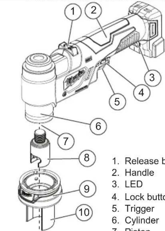
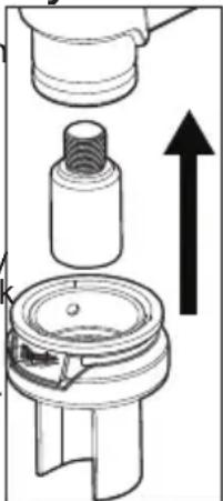
FUNCTIONAL DESCRIPTION
text_image
1. Release b 2. Handle 3. LED 4. Lock butto 5. Trigger 6. Cylinder 7. Piston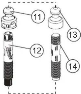
text_image
11 12 13 14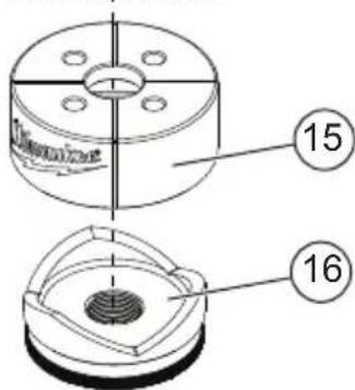
text_image
Thermometer 15 16- Release button
- Handle
- LED
- Lock button
- Trigger
- Cylinder
- Piston (inside cylinder)
- Coupler
- Quick connect anvil assembly
- Quick connect sleeve
- Rapid Reset ball pull
- Rapid Reset draw stud
- Ball pull
- Draw stud
- Die
- Punch
SYMBOLGY


Direct Current
UL Listing for Canada and U.S.
WARNING
Risk of electric shock. Do not use in or near anels.
WARNING
Keep hands away from punch and die.
Fingers could be crushed or severed. Release button
Always wear eye protection
Read Operator's Manual
ASSEMBLY
AWARNING Recharge only with the charger specified for the battery. For specific charging instructions, read the operator's manual supplied with your charger and battery.
Removing/Inserting the Battery
To remove the battery, push in the release buttons and pull the battery pack away from the tool.
⚠ WARNING Always remove battery pack before changing or removing accessories.
To insert the battery, slide the pack into the body of the tool. Make sure it latches securely into place.
AWARNING Only use accessories specifically recommended for this tool. Others may be hazardous.
Assemblying the Draw Stud and Ball Pull
Determine whether to use the Rapid Reset Draw Stud Set or the standard draw stud/ball pull. NOTE: The Rapid Reset Draw Stud Set cannot be used without the Quick Connect Assembly.
Rapid Reset Draw Stud Set
- Insert the short-grooved end of the draw stud into the ball pull.
- Turn the draw stud slightly to lock into the ball pull. The draw stud will "click" into place.
- Insert the short-threaded end of the draw stud into the ball pull.
- Screw the draw stud into the ball pull. Tighten securely.
Standard Draw Stud and Ball Pull
Installing/Removing the Quick Connect Assembly
The Knockout Tool can be used with the Quick Connect Assembly, or with the standard draw stud screwed directly into the tool.
- Remove the battery pack.
- Screw the coupler into the piston. Hand-tighten securely.
- Place the Quick Connect Assembly over the collar of the tool. Pull back on the sleeve and slide over the collar. Release the sleeve.
- To remove the Quick Connect Assembly, reverse the procedure.
natural_image
Technical diagram of a mechanical assembly with an upward arrow indicating motion (no text or symbols present)Installing/Removing the Draw Stud
In some circumstances, such as working in tight spaces, it may be necessary to use the Knockout Tool without the Quick Connect Assembly.
- Remove the battery pack.
- Remove the Quick Connect Assembly.
- Screw the standard draw stud directly into the piston. Hand tighten securely. NOTE: The Rapid Reset Draw Stud Set cannot be used without the Quick Connect Assembly.
- To remove the draw stud, unscrew from the piston.
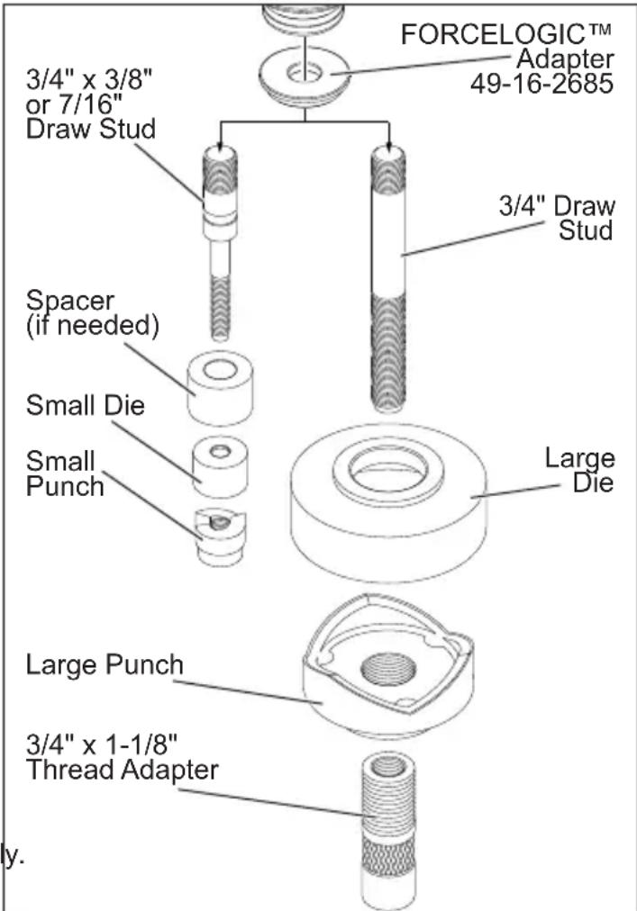
FORCELOGIC™ Adapter (some models)
Use the MILWAUKEE FORCÈLOGIC™ Adapter (Cat. No. 49-16-2685) to properly fit other major brands of small and large punches and dies. Use with other major brand draw studs and spacers, as required.
text_image
FORCELOGIC™ Adapter 49-16-2685 3/4" x 3/8" or 7/16" Draw Stud 3/4" Draw Stud Spacer (if needed) Small Die Small Punch Large Die Large Punch 3/4" x 1-1/8" Thread Adapter y.OPERATION
WARNING Always remove battery pack before changing or removing accessories. Only use accessories specifically recommended for this tool. Others may be hazardous.
To reduce the risk of injury, wear safety goggles or glasses with side shields.
To reduce the risk of injury, ensure all threads are hand-tightened securely before operating knockout tool.
Punching
- Before beginning a punch, inspect and discard material and accessories with cracks or other damage.
- Before beginning a punch, check the fuel gauge to determine whether the battery charge is sufficient to complete the operation.
- Do not attempt to punch through more than one layer of material at a time.
- Press the release button on the tool to ensure it is ready for operation.
• After 5000 punches, return the tool to a MILWAUKEE service facility for inspection and maintenance.
Preparing the Material
- Select the appropriate punch, die and draw stud for the application. See "Accessories" for chart.
- Draw cross-hairs to mark the exact location of the pilot hole.
- Drill the pilot hole slightly larger than the draw stud.
Using the Quick Connect Assembly
- Slide the draw stud through the die, then through the material.
- Place the punch under/behind the material and screw onto the draw stud.
-
Line up cross hairs on the die with those used to locate the pilot hole on the material. Tighten the punch and die securely against each side of the material to hold the assembly in place.
-
Rotate the quick connect sleeve to access the opening in the coupler.
- Slide the coupler around the ball pull.
- Rotate the sleeve to lock the ball pull into the coupler.
text_image
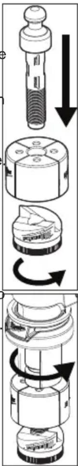
Technical diagram illustrating the step-by-step assembly of a mechanical component with directional arrows indicating motion.Punching the Material
-
Grasp the handle firmly and ensure hands and body are away from the punch and die.
-
Pull the trigger.
-
When the operation is complete, release the trigger.
-
Push the release button.
-
Rotate the quick connect sleeve and remove the ball pull from the coupler.
-
When using the Rapid Reset Draw Stud Set unconnect the ball pull from the draw stud. When using the standard draw stud and ball pull, unscrew the punch from the draw stud.
-
Remove the material. Use caution as the material edges may be sharp.
Punching without the Quick Connect Assembly
- Prepare the material as above.
- Slide the draw stud through the die, then through the material.
- Place the punch under/behind the material and screw onto the draw stud.
- Line up cross hairs on the die with those used to locate the pilot hole on the material. Tighten the punch and die securely against each side of the material to hold the assembly in place.
- Grasp the handle firmly and ensure hands and body are away from the punch and die.
- Pull the trigger.
- When the operation is complete, release the trigger.
- Push the release button.
- Unscrew the punch from the draw stud and remove the material. Use caution as the material edges may be sharp.
MAINTENANCE
WARNING
To reduce the risk of injury, always unplug the charger and remove the
battery pack from the charger or tool before performing any maintenance. Never disassemble the tool, battery pack or charger. Contact a MILWAUKEE service facility for ALL repairs.
Maintaining Tool
Keep your tool, battery pack and charger in good repair by adopting a regular maintenance program. Inspect your tool for issues such as undue noise, misalignment or binding of moving parts, breakage of parts, or any other condition that may affect the tool operation. Return the tool, battery pack, and charger to a MILWAUKEE service facility for repair. After six months to one year, depending on use, return the tool, battery pack and charger to a MILWAUKEE service facility for inspection.
If the tool does not start or operate at full power with a fully charged battery pack, clean the contacts on the battery pack. If the tool still does not work properly, return the tool, charger and battery pack, to a MILWAUKEE service facility for repairs.
WARNING
To reduce the risk of personal in-jury and damage, never immerse your tool, battery pack or charger in liquid or allow a liquid to flow inside them.
Cleaning
Clean dust and debris from vents. Keep handles clean, dry and free of oil or grease. Use only mild soap and a damp cloth to clean, since certain cleaning agents and solvents are harmful to plastics and other insulated parts. Some of these include gasoline, turpentine, lacquer thinner, paint thinner, chlorinated cleaning solvents, ammonia and household detergents containing ammonia. Never use flammable or combustible solvents around tools.
Repairs
For repairs, return the tool, battery pack and charger to the nearest service center.
ACCESSORIES
WARNING
Use only recommended accessories. Others may be hazardous.
For a complete listing of accessories, go online to www.milwaukeetool.com or contact a distributor.
SERVICE - UNITED STATES
1-800-SAWDUST (1.800.729.3878)
Monday-Friday, 7:00 AM - 6:30 PM CST or visit www.milwaukeetool.com
Contact Corporate After Sales Service Technical Support with technical, service/repair, or warranty questions.
Email: metproductsupport@milwaukeeetool.com
Become a Heavy Duty Club Member at www.milwaukeeetool.com to receive important notifications regarding your tool purchases.
SERVICE - CANADA
Milwaukee Tool (Canada) Ltd 1.800.268.4015
Monday-Friday, 7:00 AM - 4:30 PM CST or visit www.milwaukeeetool.ca
LIMITED WARRANTY USA & CANADA
Every MILWAUKEE power tool* (see exceptions below) is warranted to the original purchaser only to be free from defects in material and workmanship. Subject to certain exceptions, MILWAUKEE will repair or replace any part on an electric power tool which, after examination, is determined by MILWAUKEE to be defective in material or workmanship for a period of five (5) years** after the date of purchase unless otherwise noted. Return of the power tool to a MILWAUKEE factory Service Center location or MILWAUKEE Authorized Service Station, freight prepaid and insured, is required. A copy of the proof of purchase should be included with the return product. This warranty does not apply to damage that MILWAUKEE determines to be from repairs made or attempted by anyone other than MILWAUKEE authorized personnel, misuse, alterations, abuse, normal wear and tear, lack of maintenance, or accidents.
Normal Wear: Many power tools need periodic parts replacement and service to achieve best performance. This warranty does not cover repair when normal use has exhausted the life of a part including, but not limited to, chucks, brushes, cords, saw shoes, blade clamps, o-rings, seals, bumpers, driver blades, pistons, strikers, lifters, and bumper cover washers. *This warranty does not cover Air Nailers & Staplers; Airless Paint Sprayer; Cordless Battery Packs; Gasoline Driven Portable Power Generators; Hand Tools; Hoist – Electric, Lever & Hand Chain; M12™ Heated Gear; Reconditioned Product; and Test & Measurement Products. There are separate and distinct warranties available for these products. **The warranty period for Job Site Radios, M12™ Power Port, M18™ Power Source, Jobsite Fan and Trade Titan™ Industrial Work Carts is one (1) year from the date of purchase. The warranty period for the Cables for the Drain Snake is two (2) years from the date of purchase. The warranty period for the LED in the LED Work Light and the LED Upgrade Bulb for the Work Light is the lifetime of the product subject to the limitations above. If during normal use the LED or LED Bulb fails, the part will be replaced free of charge Warranty Registration is not necessary to obtain the applicable warranty on a MILWAUKEE power tool product. The manufacturing date of the product will be used to determine the warranty period if no proof of purchase is provided at the time warranty service is requested. ACCEPTANCE OF THE EXCLUSIVE REPAIR AND REPLACEMENT REMEDIES DESCRIBED HEREIN IS A CONDITION OF THE CONTRACT FOR THE PURCHASE OF EVERY MILWAUKEE PRODUCT. IF YOU DO NOT AGREE TO THIS CONDITION, YOU SHOULD NOT PURCHASE THE PRODUCT. IN NO EVENT SHALL MILWAUKEE BE LIABLE FOR ANY INCIDENTAL, SPECIAL, CONSEQUENTIAL OR PUNITIVE DAMAGES, OR FOR ANY COSTS, ATTORNEY FEES, EXPENSES, LOSSES OR DELAYS ALLEGED TO BE AS A CONSEQUENCE OF ANY DAMAGE TO, FAILURE OF, OR DEFECT IN ANY PRODUCT INCLUDING, BUT NOT LIMITED TO, ANY CLAIMS FOR LOSS OF PROFITS, SOME STATES DO NOT ALLOW THE EXCLUSION OR LIMITATION OF INCIDENTAL OR CONSEQUENTIAL DAMAGES, SO THE ABOVE LIMITATION OR EXCLUSION MAY NOT APPLY TO YOU. THIS WARRANTY IS EXCLUSIVE AND IN LIEU OF ALL OTHER EXPRESS WARRANTIES, WRITTEN OR ORAL. TO THE EXTENT PERMITTED BY LAW, MILWAUKEE DISCLAIMS ANY IMPLIED WARRANTIES, INCLUDING WITHOUT LIMITATION ANY IMPLIED WARRANTY OF MERCHANTABILITY OR FITNESS FOR A PARTICULAR USE OR PURPOSE; TO THE EXTENT SUCH DISCLAIMER IS NOT PERMITTED BY LAW, SUCH IMPLIED WARRANTIES ARE LIMITED TO THE DURATION OF THE APPLICABLE EXPRESS WARRANTY AS DESCRIBED ABOVE SOME STATES DO NOT ALLOW LIMITATIONS ON HOW LONG AN IMPLIED WARRANTY LASTS, SO THE ABOVE LIMITATION MAY NOT APPLY TO YOU, THIS WARRANTY GIVES YOU SPECIFIC LEGAL RIGHTS, AND YOU MAY ALSO HAVE OTHER RIGHTS WHICH VARY FROM STATE TO STATE This warranty applies to product sold in the U.S.A. and Canada only. Please consult the 'Service Center Search' in the Parts & Service section of MILWAUKEE's website www.milwaukeeetool.com or call 1.800.SAWDUST (1.800.729.3878) to locate your nearest service facility for warranty and non-warranty service on a Milwaukee electric power tool.
LIMITED WARRANTY - MEXICO, CENTRAL AMERICA & CARIBBEAN
TECHTRONIC INDUSTRIES' warranty is for 5 year since the original purchase date.
This warranty card covers any defect in material and workmanship on this Power Tool.
To make this warranty valid, present this warranty card, sealed/stamped by the distributor or store where you purchased the product, to the Authorized Service Center (ASC). Or, if this card has not been sealed/stamped, present the original proof of purchase to the ASC.
Call toll-free 1 800'832 1949 to find the nearest ASC, for service, parts, accessories or components.
Procedure to make this warranty valid
Take the product to the ASC, along with the warranty card sealed/stamped by the distributor or store where you purchased the product, and there any faulty piece or component will be replaced without cost for you. We will cover all freight costs relative with this warranty process.
Exceptions
This warranty is not valid in the following situations:
a) When the product is used in a different manners from the end-user guide or instruction manual.
b) When the conditions of use are not normal.
c) When the product was modified or repaired by people not authorized by TECHTRONIC INDUSTRIES.
Note: If cord set is damaged, it should be replaced by an Authorized Service Center to avoid electric risks.
SERVICE AND ATTENTION CENTER:
Presidente Masarik No.29 Piso 7
IMPORTED AND COMMERCIALIZED BY:
TECHTRONIC INDUSTRIES MEXICO, S.A. DE C.V.
Presidente Masarik No.29 Piso 7
Miguel Hidalgo C.P.11560 Mexico, DF.
Model:
Date of Purchase:
Distributor or Store Stamp:
RÈGLES DE SÉCURITÉ GÉNÉRALES RELATIVES AUX OUTILS ÉLECTRIQUES
AVERTISSEMENT
text_image
Technical diagram of a mechanical device with numbered parts for identification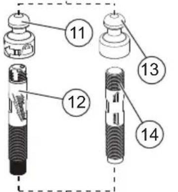
text_image
11 12 13 14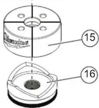
text_image
15 16natural_image
Mechanical assembly diagram showing a piston and housing with an upward arrow indicating motion (no text or symbols)text_image
Diagram illustrating three-step mechanical assembly: pin, washer, and shaker with directional arrows indicating rotation.natural_image
Mechanical assembly diagram showing a rotating component with no visible text or symbolsMilwaukee Tool (Canada) Ltd
1.800.268.4015
Monday-Friday, 7:00 AM - 4:30 PM CST
www.milwaukeetool.ca
GARANTIE LIMITÉE -
AUX ÉTATS-UNIS ET AU CANADA
Miguel Hidalgo C.P.11560 Mexico, DF
Modèle :
Date d'achat :
natural_image
Technical diagram of a mechanical assembly with an upward arrow indicating motion (no text or symbols present)text_image
Diagram showing three mechanical components with directional arrows indicating rotation or assembly steps.natural_image
Mechanical assembly diagram showing a rotating component with no visible text or symbolsLunes a Viernes (9am a 6pm)
Miguel Hidalgo C.P.11560 Mexico, DF
Tel. 52 55 4160-3547
IMPORTADO Y COMERCIALIZADO POR:
TECHTRONIC INDUSTRIES MEXICO, .S.A. DE C.V.
Presidente Masarik No.29 Piso 7
Miguel Hidalgo C.P.11560 Mexico, DF
Modelo:
Fecha de Compra:
13135 West Lisbon Road
Brookfield, WI 53005 USA