
ZIGPS182J - Powered garden tool Zipper - Free user manual and instructions
Find the device manual for free ZIGPS182J Zipper in PDF.

| Product type | Multifunction motorized gardening tool (string trimmer, hedge trimmer, pruning saw) |
| Brand | Zipper |
| Model | ZIGPS182J |
| Engine | 2-stroke, single-cylinder, 51.7 cm³, power 1.45 kW, max speed 9200 min⁻¹ |
| Ignition | CDI, spark plug CDK L8RTC (electrode gap 0.6 mm) |
| Fuel | Gas/oil mixture 40:1, tank 1.2 L |
| Weight motor unit (empty tank) | 5.6 kg |
| Weight hedge trimmer | 2.2 kg |
| Weight pruning saw | 1.1 kg |
| String trimmer - Cutting diameter (line) | 430 mm |
| String trimmer - 3-tooth blade | Diameter 255 mm, max speed 6900 min⁻¹ |
| Hedge trimmer - Cutting length | 425 mm, tooth pitch 20 mm, speed 1550 min⁻¹ |
| Pruning saw - Cutting length | 260 mm, chain speed 20 m/s |
| Chain oil tank | 140 ml |
| Guaranteed sound power level | 114 dB(A) |
| Vibrations (string trimmer) | a_h,D = 6.204 m/s², k=2.5 m/s² |
| Vibrations (hedge trimmer) | a_h,D = 6.938 m/s², k=2.5 m/s² |
| Vibrations (pruning saw) | a_h,D = 5.723 m/s², k=2.5 m/s² |
| Regular maintenance | Cleaning after each use, air filter every 25h, spark plug every 25h, gear lubrication every 25h |
| Safety | Wear PPE (gloves, goggles, helmet, hearing protection), respect safety distances (15 m), do not use in confined spaces |
| Warranty | 2 years non-commercial use, 1 year commercial use |
Frequently Asked Questions - ZIGPS182J Zipper
User questions about ZIGPS182J Zipper
0 question about this device. Answer the ones you know or ask your own.
Ask a new question about this device
Download the instructions for your Powered garden tool in PDF format for free! Find your manual ZIGPS182J - Zipper and take your electronic device back in hand. On this page are published all the documents necessary for the use of your device. ZIGPS182J by Zipper.
USER MANUAL ZIGPS182J Zipper
natural_image
Product photo of green and black utility hedges with various tools (no visible text or labels)ZI-GPS182J
CE
EAN: 9120039233215

1 INHALT / INDEX / SOMMAIRE
1 INHALT / INDEX / SOMMAIRE 2
2 SICHERHEITSZEICHEN / SAFETY SIGNS / SYMBOLES DE SECURITE / VARNOSTNE OZNAKE 5
11.1 Intended Use....29
11.2 Safety instructions .... 30
11.3 Remaining risk factors....32
12 ASSEMBLY 33
12.1 Assembly 33
12.1.1 Fitting the boom 34
12.1.2 Removing the boom 34
12.1.3 Swivelling the hedge trimmer 34
12.1.4 Mounting the saw chain and blade.... 34
12.1.5 Removing the saw chain 34
12.1.6 Tightening and checking the saw chain 35
12.1.7 Lubricating the chain 35
12.1.8 Attaching the boom (extension) 35
12.1.9 Fitting/removing the protective guard 35
12.1.10 Installing/replacing the cutting blade 35
12.1.11 Installing/replacing the strimmer 36
13 OPERATION 37
13.1 Operation instructions.... 37
13.2 Operation 37
13.2.1 Cold start 37
13.2.2 Warm start 37
13.2.3 Switch off the engine 38
13.3 Trimming / mowing....38
13.4 Hedge trimmer 39
13.5 Pole pruner....39
14 MAINTENANCE 40
14.1 Cleaning 40
14.1.1 Cleaning the pole pruner 40
14.1.2 Cleaning the hedge trimmer 40
14.1.3 Cleaning the strimmer/3-section cutting blade attachment 41
14.1.4 Cleaning the air filter 41
14.1.5 Spark plug 41
14.1.6 Carburettor 41
14.1.7 Adjusting the throttle cable 41
14.1.8 Lubricating the gears 41
14.2 Replacing the strimmer/cutting strimmer cord 42
Storage....42
14.4 Disposal....42
15 TROUBLE SHOOTING 43
16 AVANT-PROPOS (FR) 44
17 SECURITE 45
EN EC-CONFORM - This product complies with the EC-directives.
EN READ THE MANUAL! Read the user and maintenance manual carefully and get familiar with the controls in order to use the machine correctly and to avoid injuries and machine defects.
EN ATTENTION! Ignoring the safety signs and warnings applied on the machine as well as ignoring the security and operating instructions can cause serious injuries and even lead to death.
EN Protective clothing!
natural_image
Four black circular icons representing different workplace safety symbols: head, helmet, hand gesture, and boot (no text or labels)


EN Caution! Falling objects. Especially when cutting above head height.
EN Highly flammable!
FR Facilement inflammable!
SL Lahko vnetljivo!
EN Do not touch the cutting tool!
EN The cutting tool continues running after it is turned off!
EN Warning against thrown-off items!
DE Vorsicht vor Rückstoß!
EN Beware of kick back!
FR Prendre garde au contrecoup !
SL Pozor, nevarnost povratnega udarca!
DE Schalleistungspegel LWA
EN Sound power level L_WA
FR Niveau de puissance sonore LWA
SL Nivo zvočne moči LWA
DE Achtung! Erstickungsgefahr!
EN Caution! Risk of suffocation!
FR Attention ! Risque de d'étouffement !
SL Pozor! Nevarnost zadušitve!
EN Attention! Poisonous CO vapours! Do not use the appliance in closed rooms!!
EN Turn the machine off and disconnect the spark plug before performing any maintenance work!
EN Fire, naked flame and smoking forbidden!
EN Warning! Do not use circular saw blades for the cutting blade function!
EN Protect the appliance from rain and moisture!
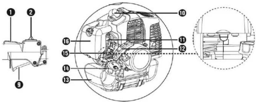
| 1 | Einschaltspere / safety lock-out / Dispositif de blocage d'enclenchement /klopnazapora | 29 | Öltank / oil tank / Réservoir d'huile / Rezervoar za olje |
| 2 | EIN- AUS-Schalter / ON-OFF switch / Commutateur marche-arrêt / Stikalo za VKLOP | 30 | Schwert./ blade / Lame / Zagin list |
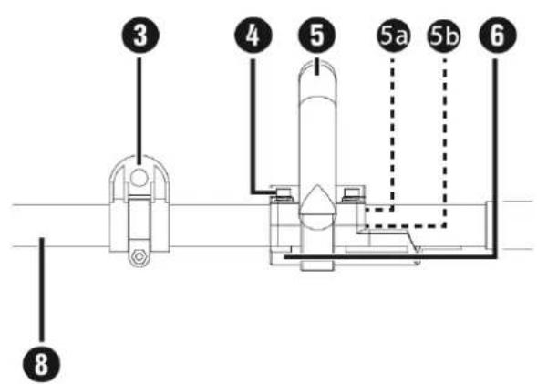
| 3 | Gurtöse / carrying lug / Anneau de transport / Nosilno uho | 31 | Sägekette / saw chain / Chaîne de scie / Veriga žage |
| 4 | Befestigungsschrauben / fixing bolts / Vis de fixation / Pritrdilni vijaki | 32 | Schleifbockhilfe / grinder support / Auxiliaire de dispositif d'affûtage / Opora zob |
| 5 | Rundgriff / round handle / Poignée arrondie / Okrogel ročaj | 33 | Anschlag / stop / Butée / Omejevalo |
| 5a | Gummiring / rubber ring / Bague en caoutchouc / Gumijasti obroč | 34 | Arretierungsstift / locking pin / Goupille de blocage / Aretirni zatič |
| 5b | Stift / pin / Goujon / Zatič | 35 | Antriebswelle / drive shaft / Arbre de transmission / Pogonska gred |
| 6 | Barrierebügel / barrier bar / Équerre de blocage / Pregradni nastavek | 36 | Mutter / nut / Écrou / Matica |
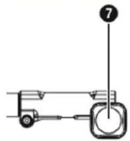
| 7 | Schraubgriff / Screw grip / Poignée vissée / Vijačni ročaj | 37 | Gewinde / thread / Fil / Navoj |
| 8 | Ausleger / Boom / Bras / Drog | 38 | Kettenradabdeckung / sprocket cover / Cache de chaîne / Pokrov zobnika verige |
| 9 | Gashebel / throttle control / Poignée des gaz / Ročica za plin | 39 | Schwertführung / blade guide / Guidage de la lame / Vodilo žaginega lista |
| 10 | Zündkerzenstecker / spark plug connector / Cosse de bougies d'allumage / Vtič za svečko | 40 | Schwertbohrung / blade hole / Alésage de lame / Vrtina v žaqinem listu |
| 11 | Choke-Hebel / choke lever / Levier de choke / Ročica za zauq | 41 | Führungsschiene / guide rail / Rail de guidage / Vodilna tirnica |
| 12 | Startseilzug / starter pull cord / Cordon de démarrage / Vrvični zaganjalnik | 42 | Tropföler / oil dispenser / Huileur compte-gouttes / Oljna mazalka |
| 13 | Benzintank / fuel tank / Réservoir d'essence / Rezervoar za gorivo | 43 | Kettenrad / chain sprocket / Pignon de chaîne / Zobnik verige |
| 14 | Tankdeckel / fuel filler cap / Bouchon de réservoir / Pokrov rezervoarja za gorivo | 44 | Ölregulierungsschraube / oil adjustment screw / Vis de régulation de l'huile / Regulirni vijak za olje |
| 15 | Kraftstoffpumpe „Primer“ / fuel pump (primer) / Pompe à essence « Primer » / Črpalka za gorivo „Primer“ | 45 | Kettenspannstift / chain tensioner pin / Goupille de serrage de chaîne / Zatič za napenjanje verige |
| 16 | Abdeckung Luftfiltergehäuse / air filter housing cover / Cache du boîtier de filtre à air / Pokrov ohišja zračnega filtra | 46 | Kettenspannschraube / chain tensioner screw / Vis de serrage de chaîne / Vijak za napenjanje verige |
| 17 | Handgriff / handle / Poignée / Ročaj | 47 | Vis / boulons / vis / Ojnični vijak |
| 18 | Verriegelung / lock / Verrouillage / Zapora | 48 | Schutzhaube / blade guard / Capot de protection / Zaščitni pokrov |
| 19 | Getriebegehäuse / transmission case / Carter de transmission / Ohišje pogona | 49 | 3 Zahn-Schnittmesser / 3-section cutting blade / Lame de coupe à 3 dents / 3-zobni rezalni nož |
| 20 | Messerbalken / cutter bar / Barre porte-lames / Prečka z rezili | 50 | Fadenspule mit Schnittfaden / strimmer with cutting strimmer cord / Coupe-bordure avec fil de coupe / Navitek rezalne nitke |
| 21 | Grundplatte (Heckenschere) / base plate (hedge shears) / Embase (taille-haies) / Osnovna plošča (škarij za živo mejo | 51 | Vorderer Ausleger / front boom / Bras avant / Sprednji drog |
| 22 | Stellhebel / control lever / Levier de réglage / Nastavni vzvod | 52 | Arretierungsstift / locking pin / Goupille de blocage / Aretirni zatič |
| 23 | Vorderer Ausleger (Heckenschere) / Front boom (hedge trimmer) / Bras avant (taille-haies) / Sprednji drog (škarij za živo mejo) | 53 | Antriebswelle / drive shaft / Arbre de transmission / Pogonska gred |
| 24 | Arretierungsstift / locking pin / Goupille de blocage / Aretirni zatič | 54 | Ausleger (Verlängerung) / boom (extension) / Bras (prolongement) / Drog (podaljšek) |
| 25 | Antriebswelle / drive shaft / Arbre de transmission / Pogonska gred / | 55 | Schraubgriff / screw grip / Poignée vissée / Vijačni ročaj |
| 26 | Vorderer Ausleger (Hochentaster) / front boom (pole pruner) / Bras avant (perche élagueuse) / Sprednji drog (tipka za nastavitev višine | 56 | Arretierungsstift / locking pin / Goupille de blocage / Aretirni zatič |
| 27 | Schutzring / safety ring / Anneau de garde / Zaščitni obroč | 57 | Antriebswelle / drive shaft / Arbre de transmission / Pogonska gred |
| 28 | Öltankdeckel / oil filler cap / Bouchon de réservoir d'huile / Pokrov rezervoarja za olje | 58 | Getriebeschraube / gear screw / Vis d'engrenage / Vijak pogona |
3.2 Lieferumfang / delivery content / Contenu de la livraison / Vsebina pošiljke

natural_image
Collection of various mechanical and electronic components including a device, cylindrical parts, and tools (no text or symbols visible)3.3 Technische Daten / technical data / Données techniques / Tehnični podatki
natural_image
Person wearing a checkered shirt and carrying a device, no visible text or symbols
natural_image
Person wearing a checkered shirt and belt with black straps, no visible text or symbols
natural_image
Person wearing a full-body harness and belt, hands visible adjusting the chest (no text or symbols)
natural_image
Person wearing a checkered shirt and black safety harness, hands adjusting the belt (no text or symbols visible)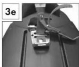
natural_image
Close-up of a mechanical component with wires and a labeled section '3e' (no readable text or symbols)
natural_image
Close-up of a mechanical device with a tool and labeled part '3f' (no readable text or symbols beyond labels)
natural_image
Close-up of a mechanical component with a labeled section '3g' and a force indicator (F), no readable text or symbols beyond the label.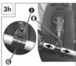
natural_image
Close-up of a person using a mechanical tool or device, no visible text or symbols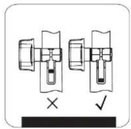
natural_image
Diagram showing two mechanical components with cross and check symbols, no readable text or labels7.2.2 Warmstart
7.4 Heckenschere
7.5 Hochentaster
WARNUNG
natural_image
Technical illustration of a mechanical tool with a bracket and a close-up view showing the blade assembly (no text or symbols)
8.1.6 Vergaser
HINWEIS
natural_image
Mechanical assembly diagram showing a rotating component with labeled point D (no text or symbols present)This manual contains important information and advice for the correct and safe use and maintenance of the garden maintenance set ZI-GPS182J.
Following the usual commercial name of the machine (see cover) is substituted in this manual with the name "machine".
The manual is part of the machine and may not be stored separately. Read it profoundly before first use of the machine and keep it for later reference. When the machine is handed to other persons always put the manual to the machine.
Please follow the security instructions!
Please read the entire manual, to prevent misunderstandings, machine damage or even injuries!

Due to continuous development of our products illustrations, pictures might differ slightly.
If you however find errors in this manual, please inform us.
Technical changes excepted!
Copyright law
© 2017
This manual is protected by copyright law – all rights reserved. Especially the reprinting as well as the translation and depiction of pictures will be prosecuted by law. Court of jurisdiction is the Landesgericht Linz or the competent court for 4707 Schlüsslberg, AUSTRIA.
Customer Support
The machine must only be used for its intended purpose! Any other use is deemed to be a case of misuse. To use the machine properly you must also observe and follow all safety regulations, the assembly instructions, operating and maintenance instructions lay down in this manual.
All people who use and service the machine have to be acquainted with this manual and must be informed about the machine's potential hazards.
It is also imperative to observe the accident prevention regulations in force in your area.
The same applies for the general rules of occupational health and safety.
The machine is used for:
Trimmer: For trimming and cutting grass, lawns, undergrowth and small weeds
Hedge trimmer: For cutting branches and fresh shoots of hedges and bushes
Branch saw: For the separation of branches of standing trees
This machine is not intended for use by persons (including children) with reduced physical, sensory or mental capabilities, or lack of experience and knowledge, unless they have been given supervision or instruction concerning use of the machine by a person responsible for their safety. Never allow children or people unfamiliar with these instructions to use the machine. Supervise children. This will ensure that children do not play with the machine.
Any manipulation of the machine or its parts is a misuse, in this case ZIPPER-MASCHINEN and its sales partners cannot be made liable for ANY direct or indirect damage.
WARNING

- Use only cutting tools allowable for this machine!
- Never use a damaged cutting tools!
- Never use the machine with defective or without mounted guard!
- The removal or modification of the safety components may result in damage to equipment and serious injury!
HIGHEST RISK OF INJURY!
Ambient conditions
The machine may be operated:
humidity
max. 90%
Temperature
from +5°C to +40°C
Prohibited use:
- The operation of the machine outside the stated technical limits described in this manual is forbidden.
- The operation of the machine without provided protective devices is prohibited.
- The use of the machine not being suitable for the use of the machine and not being certified is forbidden
- The use of the machine not according with the required dimensions is forbidden.
- Any manipulation of the machine and parts is forbidden.
• The use of the machine for any purposes other than described in this user-manual is forbidden. - It is not allowed to leave the immediate work area during the work is being performed.
For the trimmer applies:
- The device must not be used in public spaces, parks, sports venues or along roads and in the agriculture and forestry.
- The device must not be used for cutting and chopping:
o hedges, shrubs and bushes
- of flowers within the meaning of compost material.
For the hedge trimmer applies:
- As a hedge trimmer for private domestic and hobby gardens such devices are considered, which are not used in public spaces, parks, sports venues as well as in agriculture and forestry.
- The hedge trimmer may not be used for cutting grass, lawn edges or for crushing for composting.
For the branch saw applies:
- The branch saw no use for felling trees, saplings or bushes.
- The branch saw no use for cutting building materials and plastics.
• The branch saw is suitable only for private use in the home and hobby gardens. - The branch saw is not suitable for forestry work (removing branches in the forest).
11.2 Safety instructions
Missing or non-readable security stickers have to be replaced immediately! To avoid malfunction, machine defects and injuries, read the following security instructions!
The locally applicable laws and regulations may specify the minimum age of the operator and limit the use of this machine!
• Use the machine only in good enough light to allow a safe operation can be guaranteed.
- In tiredness, decreased concentration or under the influence of alcohol or drugs, the work on the machine is prohibited!
- Caution in slippery conditions - slip hazard - risk of injury. When working, robust and non-slip footwear. Slides / stumble / traps are a major cause of serious injury or death.
- The machine may only be operated by trained personnel.
- Unauthorized persons, especially children and not trained personnel must be kept away from the running machine!
• If you pass the machine to third, these instructions must be attached to the machine.
- Before each use, the reliability of the machine is to be checked (tightness of the cutting tool, the proper function of the throttle lever)
- Danger of burns! During the operation flow of hot exhaust gases and engine parts such as the carburettor and engine become hot.
• Never place a hot brush cutter in dry grass or other easily flammable materials.
• After the operation, the machine must cool down. Otherwise there is an imminent risk of burns
- WARNING: Gasoline is highly flammable!
- Smoking and open flames are prohibited during refuelling. Do not refuel when the engine and carburettor are still very hot.
- Refuel only outdoors or in a well ventilated area.
- Avoid contact with skin and clothes (fire hazard).
- Check after refuelling tank cap and check for leaks.
- Start the engine at least 3 meters from the tank location.
- Spilled fuel is wipe immediately.
- Work attentively, safety conscious and always be fully aware safe stand when working! Caution on uneven work surfaces and work surfaces with a slope!
- Regular breaks reduce the security risk to loss of control due to fatigue. Change the working position over again.
- Avoid abnormal posture.
- At idle, the blade should not rotate!
- The maximum shaft speed must not exceed the specified speed. Checked settings!
- No other person shall remain within 15m!
• This distance also adhere to things! Danger of damage!
• Solid objects, stones, metal parts, or the like can be thrown out - risk of injury!
- Use personal safety equipment: ear protectors, safety goggles, safety shoes and safety helmet when working with the machine
- Never leave the machine running unattended! Before leaving the working area switch the machine off and wait until the machine stops.
- Switch off the machine before maintenance or adjustment.
- Storage always with an empty tank in a safe place.
- Do not grab in the cutting tool while it is rotating.
• Take care that you do not get under the cutting tool!
• Always use the correct cutting tool for the work to be done.
- Do not operate in an enclosed or confined areas.
- Exhaust contains poisonous carbon monoxide. The exposure can cause unconsciousness and death.
- Before the start, after the failure or shock, be sure to check the device and make sure that it is in good condition.
- Wear firm gloves when you use the brush cutter or if you install or remove the cutting blade.
TRIMMER:
- Never cutting: above hip height, on a ladder, on trees
- Regular breaks reduce the security risk to loss of control due to fatigue. Change the working position over again. Avoid abnormal posture
- Trim always perpendicular to the slope, never up and down
- No other person shall remain within 15m!
• This distance also adhere to things! - Use personal safety equipment: safety googles or face protection, safety helmet, safety shoes, work wear when working with the machine
• Wear safety gloves when work with the trimmer and work or change on the cutting blades - To prevent damage to the machine never grind but lift completely.
• Always cut diagonally to the slope. Do not mow on excessively steep gradients. - Take extra care when walking backwards. You may stumble! Always work at a walking pace, never run!
- Inspect the area to be cut before you begin work. Remove any foreign objects (such as stones). Look out for foreign objects (such as stones) while you are working.
BRANCH SAW:
- Regular breaks reduce the security risk to loss of control due to fatigue. Change the working position over again. Avoid abnormal posture
• Always start cutting with full chain speed - Pruning only remove chain is running out of the cut.
- Do not remove the same the whole road, but they work piecemeal from the end of the branch in the direction of strain.
- No other person shall remain within 15m!
• This distance also adhere to things! - Be careful at the end of the cut. Change in weight can lead to accidents.
- Keep balance and be cautious of falling branches.
- Do not use the branch saw in the vicinity of cables, power or telephone lines..
• Hold when working with the branch saw a safety distance of 10m to aboveground live lines. - Use personal safety equipment: safety googles or face protection, safety helmet, safety shoes, work wear when working with the machine
- Wear safety gloves when work with the trimmer and work or change on the cutting blades
- To prevent damage to the machine never grind but lift completely.
- Never cut with the tip of the blades. It may cause kickback!
HEDGE TRIMMER:
- Regular breaks reduce the security risk to loss of control due to fatigue. Change the working position over again. Avoid abnormal posture
- No other person shall remain within 15m!
• This distance also adhere to things! - Not to pick up objects using
- Use personal safety equipment: safety googles or face protection, safety helmet, safety shoes, work wear when working with the machine
- Wear safety gloves when work with the trimmer and work or change on the cutting blades
• Cutting always start with running blades
• Take care to do not touch the blades!
TRANSPORT NOTES:
- Switch off the engine
- Fit the blade guard
- Secure the machine
• Empty tank completely, avoid fuel spillage
• To avoid damage to the device never drag but always lift correctly.
STORAGE NOTES:
- Remove and clean thread head and cutter blade
- Fit the blade guard
- Clean the machine and dry
• Empty Tank completely, avoid fuel spillage
• Store in a dry, out of reach of children place, well packaged (protection against cuts)
11.3 Remaining risk factors
Even if the machine is used as required it is still impossible to eliminate certain residual risk factors totally. The following hazards may arise in connection with the machine's construction and design:
- Risk of injury due to noise:
Working for a long time can damage your hearing if you do not have a very good hearing protection.
- Risk of injury due to the working area:
Solid objects, stones, metal parts, or the like can be thrown out!
- Risk to the hands or fingers:
Do not grab in the cutting tool while it is rotating.
- Risk of injury due to pick up and roll up:
Wires and cords can be detected by the cutting tool and can damage the machine and can cause injuries. Unplug battery and safety switch (if equipped) before removing the deposits!
- Risk of burns:
Touching the mufflers, exhaust and other machine components which can be hot after prolonged continuous operation or when the engine is hot cause severe burns.
- Risk of fire and explosion:
Gasoline is highly flammable and explosive under certain conditions.
NEVER refuel fuel or engine oil while the machine is in operation or is hot.
When refueling and at places where fuel is stored not smoke or allow open flames or sparks.
Do not overfill the fuel tank and avoid the spillage of gasoline during refueling. If fuel is spilled make sure the area is completely dry and cleaned before starting the engine.
Make sure that the filler cap is tightly closed again after refueling safely.
- Chemical risks:
Never use or refuel a gasoline or diesel engine in a closed area without adequate ventilation.
Carbon monoxide emissions from the internal drive units of the engine can cause in confined spaces through inhalation health effects and death. Therefore use the machine only in well-ventilated rooms or outdoors in operation.
Liquid fuels can cause serious damage on the skin and the environment.
- Vibration:
The declared vibration emission value has been for a standardized test is measured and can be used to compare one tool with another electric are. The declared vibration emission value may also be used for a preliminary assessment of exposure.
Warning:
Emission level of vibration can be different from the specified value during the actual use of the electric tool, depending on the manner in which the power tool is used. When you feel uncomfortable or notice discoloration of skin on your hands during the use of the machine, stop working immediately. Observe sufficient break times to rest. Failure to have sufficient break times may result in a hand-arm vibration syndrome.
The extent of exposure depending on the type of work or machine use should be estimated and appropriate breaks taken. In this way, the extent of exposure can be considerably reduced over the entire work time. Minimize the risk caused by vibrations. Maintain this machine according to the instructions in the manual.
- Kickback:
When working with metal cutting blades, it can, if fixed objects (trees, branches, stones, or the like) are involved, come to a check of the entire unit or to an abrupt train forward.
This check occurs suddenly without warning and can lead to loss of control of the unit and endanger the user and bystanders.
Special Threatened in poor visibility areas and dense vegetation.
12 ASSEMBLY
Please check the product contents immediately after receipt for any eventual transport damage or missing parts. Claims from transport damage or missing parts must be placed immediately after initial machine receipt and unpacking before putting the machine into operation. Please understand that later claims cannot be accepted anymore.
12.1 Assembly
Round handle:
- Start by fitting the rubber ring (5a) on the boom (8).
- Attach the barrier bar (6) onto the rubber ring (5a) from below.
- The pin (5b) on the barrier bar (6) must be pushed into one of the two holes on the boom (8) to lock it into place.
- Push the round handle (5) onto the rubber ring (5a) provided on the boom (8).
- Insert the 4 mounting bolts (4) from above through the round handle (5) and secure them with the 4 nuts in the barrier bar (6).
- Tighten the bolts (4).
Quick release mechanism:
- Hook in the carabiner and secure it with the red strap on the quick release mechanism.
- Pull on the red strap if you have to release the appliance quickly.

natural_image
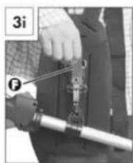
Three mechanical components with curved and straight lines, shown from different angles (no text or symbols visible)Carrying harness:
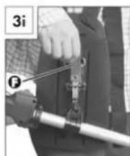
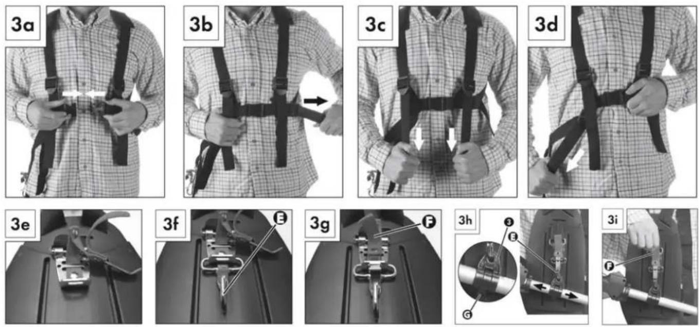
- Hook the carrying harness (58) into the carrying lug (3).
- Adjust the length of the carrying harness (58) to your size (3a-3i), that the carrying lug (3) is at hip height when hooked in place.
12.1.1 Fitting the boom
- Start by undoing the screw grip (7) on the boom (8) of the motor unit.
- Slide the tab on the front boom (23, 56, 51) onto the boom (8) of the motor unit.
- Must properly inserted the red line be flush with the boom of the motor unit.
- If this is not possible, pull the starter pull cord to adjust the shaft. Caution! Switch the on/off switch (2) to „0".
- Tighten the screw grip (7).
12.1.2 Removing the boom
- Undo the screw grip (7) and pull the front boom (23, 56, 51) out of the boom (8) on the motor unit.
natural_image
Mechanical assembly diagram showing a lever and pulley system with no text or symbols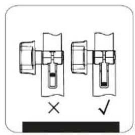
natural_image
Diagram showing two mechanical or electrical component assemblies with cross and check symbols (no text or labels)12.1.3 Swivelling the hedge trimmer
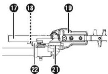
- Release the lock (18).
- Press the control lever (22) and swivel the hedge trimmer into the desired position.
- Allow the control lever (22) o click into the recess in the base plate (hedge trimmer) (21).
12.1.4 Mounting the saw chain and blade


NOTICE
- Wear protective gloves! There is a danger of injury from the sharp cutting teeth.
- Pay close attention to the running direction of the saw chain on the blade and at the base plate (pole pruner)
-
Depending on wear, the blade can be turned.
-
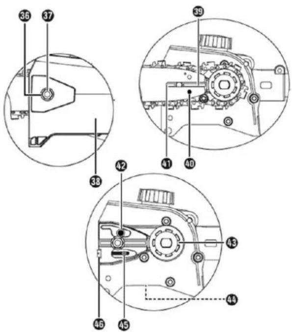
Undo the nut (36) using the open-ended spanner.
- Remove the sprocket cover (38).
- Lay the saw chain (31) over the blade (30) starting at the tip.
• Now fit the blade (30) and saw chain (31). - Lay the guide rail (41) over the blade guide (39) while inserting the chain tensioner pin (45) in the blade hole (40). At the same time, lay the saw chain (31) over the chain sprocket (43).
- Now you can tighten the saw chain (31) (see section "Tightening and checking the saw chain").
- Replace the sprocket cover (38) and tighten the nut (36) gently.
12.1.5 Removing the saw chain
- You may have to loosen the saw chain (31) to remove the blade (30) and the saw chain (31) (see section "Tightening and checking the saw chain"). Follow these instructions in reverse order.
12.1.6 Tightening and checking the saw chain
- Turn the chain-tensioner screw (46) in a clockwise direction using the flat-blade screwdriver to increase the tension.
- The saw chain (31) must lie against the underside of the blade. Check whether the saw chain (31) can be drawn by hand over the blade (30).
12.1.7 Lubricating the chain

WARNING
- Never work without chain lubrication!
-
If the saw chain runs dry, the cutting equipment may become irreparably damaged in a short time. Always check chain lubrication and oil level in the tank before starting work.
• While working, check whether the chain lubrication is working correctly. -
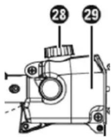
Remove the oil filler cap (28).
- Fill the oil tank (29) with approx. 140 ml of chain oil!
- The chain lubrication can be increased or decreased using the oil adjusting screw (44).
- Press and then turn the oil adjusting screw (44) clockwise to decrease the chain lubrication.
- Press and then turn the oil adjusting screw (44) anticlockwise to increase the chain lubrication.
12.1.8 Attaching the boom (extension)
- Fit the boom (extension) (54) between the motor unit and the hedge trimmer/pole pruner.
- The assembly is carried out in the same manner as for the attachments described previously.
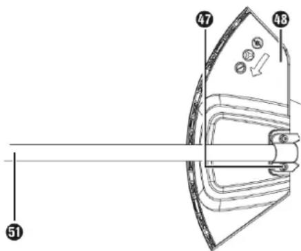
12.1.9 Fitting/removing the protective guard
- Fold the metal sheet of the front boom (51) down slightly. The protective cover (48) s positioned between the metal sheet and the boom (51) mounting arm.
- The protective guard (48) is now attached to the front boom (51) with 4 screws (47).
- Use the supplied Allen key and the open-ended spanner.
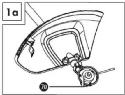
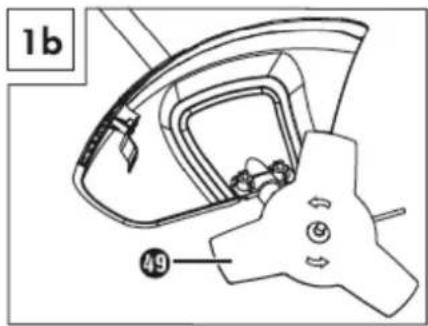
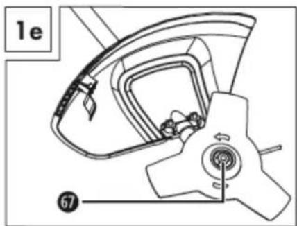
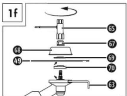
12.1.10 Installing/replacing the cutting blade
- Fit/remove the 3-section cutting blade as shown in Figures 1a–1f.
- Find the hole in the drive plate, align it with the opposite hole and block it with the supplied Allen key.
- Place the 3-section cutting blade on the drive plate (see Fig. 1b). The label must be visible in working position from above
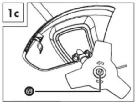
- Fit the pressure plate over the thread on the splined shaft (see Fig. 1c).
• Fit the pressure plate cover (see Fig. 1d). - Now tighten the nut 6(with the spark plug wrench anti clockwise. CAUTION! Left-hand thread! (see Fig. 1f).
- The 3-section cutting blade is fitted with a plastic cover on delivery. This must be removed before use and refitted during periods when not in use.
-
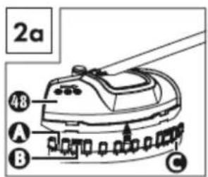
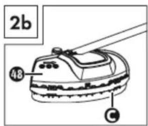
Fit the cutting Strimmer cord protective guard C on the protective guard.
-
The cutting Strimmer cord protective guard C must be fitted when working with the cutting Strimmer cord. The cutting Strimmer cord protective guard C (pre-fitted on delivery) is fitted as shown in Figure 2a.
- Ensure that the cutting Strimmer cord protective guard C is correctly clicked into place. There is a blade A on the inside of the cutting Strimmer cord protective guard C. This is covered with a safety cover B (see Fig. 2a.).
- Remove the safety cover B before starting work and replace it after finishing work.
- To remove the cutting Strimmer cord protective guard C from the protective guard, take a tool, such as a screwdriver, to carefully remove the three mounting pins.
natural_image
Technical line drawing of a mechanical device with labeled parts (1c and 69), no readable text or symbols beyond labels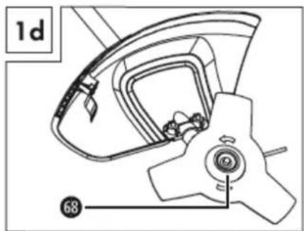


12.1.11 Installing/replacing the strimmer
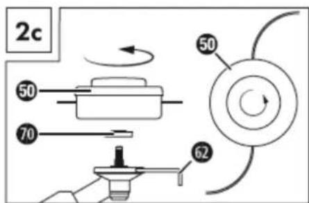
• Fit/remove the strimmer as shown in Figure 2c.
- Find the hole in the drive plate, align it with the opposite hole and block it with the supplied Allen key.
- Screw the strimmer anticlockwise onto the thread. CAUTION! Left-hand thread!
13 OPERATION
Machine to be operated in a perfect state only. Inspect the device visually every time it is to be used. Check in particular the safety equipment, electrical controls, electric cables and screwed connection for damage and if tightened properly. Replace any damaged parts before operating the device.
13.1 Operation instructions
NOTICE
- Shut off the machine and let it cool down before start any cleaning, upkeep, checks or maintenance!
- Operate the machine always with belt!
- In dangerous situations detach the machine with the quick release from shoulder strap
- Make sure the fuel and tank are in perfect condition before each start!
- Before using practice all working techniques with the engine stopped.
13.2 Operation
13.2.1 Cold start
WARNING
Always pull the starter pull cord straight out. Hold the handle of the starter pull cord firmly when the starter pull cord retracts. Do not allow the starter pull cord to whip back.
1.) Fill the fuel tank (13) with the right fuel.
2.) Press the primer (15) 6 x times.
3.) Switch the ON-OFF switch (2) to „I”.
4.) Pull the choke lever (11) to position „|↘|”.
5.) Hold the appliance firmly and pull out the starter pull cord (12) to the point of first resistance. Now pull hard on the starter pull cord (12). The machine starts.
6.) If the engine does not start, repeat steps 4–5.
7.) As soon as the engine is running, press the safety lock-out (1) and then press the throttle (9), to activate the automatic choke.
13.2.2 Warm start
1.) Switch the ON-OFF switch (2) to „I”.
2.) The choke lever (11) does not need to be pulled out to start a warm motor.
3.) Hold the appliance firmly and pull out the starter pull cord (12) to the point of first resistance. Now pull hard on the starter pull cord (12). The machine should start after 1-2 pulls. If the machine still hasn't started after 6 pulls, repeat steps 1-7 under "Cold start".
13.2.3 Switch off the engine
If you need to stop the appliance immediately, switch the ON-OFF switch (2) to „0".
In normal sequence release the throttle lever (9) and wait until the engine has slowed down to its idling speed. Then switch the ON-OFF switch (2) to „0".
13.3 Trimming / mowing
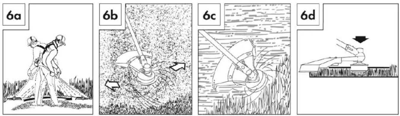
- Swing the appliance in a scything motion (see Fig. 6a).
- Hold the cutting tool parallel to the ground and set the desired cutting height.
Low trimming with strimmer:
- Hold the appliance with a slight incline to the ground (see Fig. 6b). Always cut away from your body. Never pull the appliance towards you.
Short mowing with strimmer:
- Short mowing removes all the vegetation right down to the ground. Angle the strimmer 30^ to the right. Set the handle to the desired position (see Fig. 6c).
Extending the cutting Strimmer cord:
- To lengthen the cutting Strimmer cord, rev the engine to full throttle and tap the strimmer on the ground. The Strimmer cord extends automatically.
- The knife A on the cutting Strimmer cord protective guard C cuts the thread to the permissible length (see Fig. 6d).
Jamming:
Immediately turn off the engine if the cutting tool becomes blocked. Remove all grass and scrub from the appliance before restarting the appliance.
13.4 Hedge trimmer
- The double-sided cutter bar allows cutting in both directions or by using swinging movements from one side to the other.
- For a vertical cut, move the hedge trimmer evenly forwards or up and down in an arc.
- For a horizontal cut, move the hedge trimmer in a scything motion along the edge of the hedge so that cut branches fall to the ground. Remove thicker branches with a branch cutter.
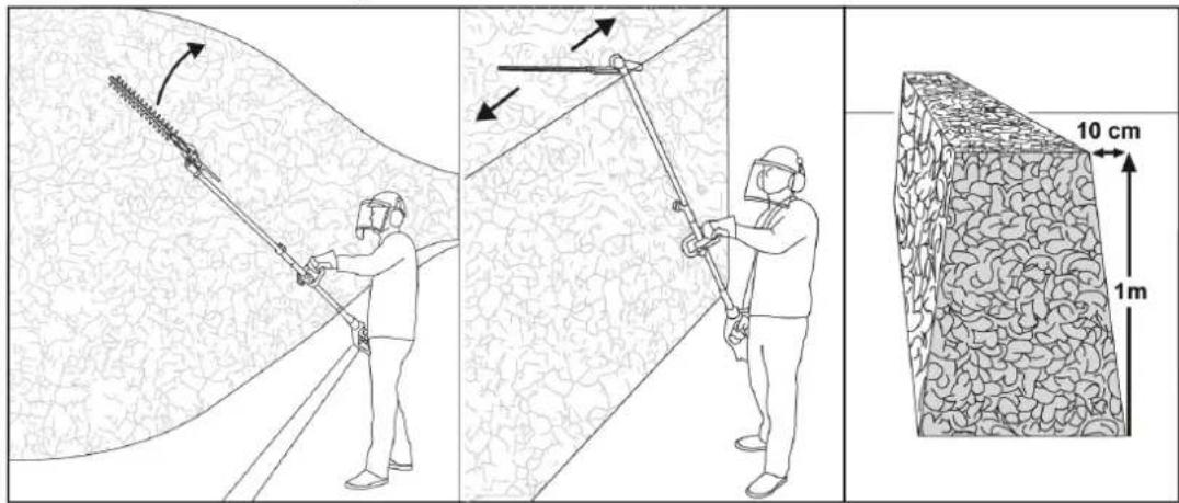
13.5 Pole pruner
WARNING
- Pay attention to falling clippings.
- Be aware of the danger of branches flying back.
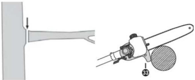
Sawing off small branches:
- Place the stop (33) on the branch. This will help you work more safely and quietly.
- Saw small branches ( 0–8 cm) from the top down.
natural_image
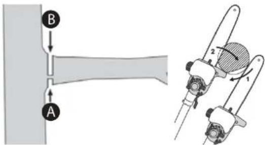
Technical illustration of a mechanical tool and its assembly, showing a bracket and a cutting tool (no text or symbols)Sawing off larger branches:
- When sawing larger branches ( 8–25 cm), first make a relief cut A. A relief cut also prevents peeling of the bark on the main trunk.
- Saw from the top B to the bottom A.
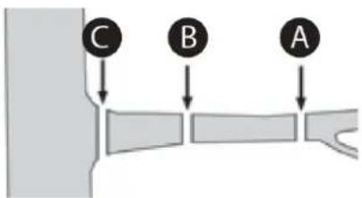
Saw in sections:
- Trim long or thick branches before you make the final cut.
14 MAINTENANCE
ATTENTION
Turn the machine off, disconnect the spark plug and let the machine cool down before performing any maintenance work!
The machine does not require intense maintenance. However, to ensure a long lifespan, we strongly recommend following the upkeep and maintenance plan.
Repairs must be carried out by specialists! Use original ZIPPER parts only!
Ware safety gloves if you are work on the cutting tool!
Damaged cutting tools may never be straightened or welded!
NOTICE
Only a properly maintained equipment may be a satisfactory tool. Care and maintenance deficiencies can cause unpredictable accidents and injuries.
Repairs should be performed only by authorized service centers.
Improper operation may damage the equipment or endanger your safety.
| Controls for the maintenance of the machine | |
| Loose or lost screws, nuts, bolts | Regularly prior to each operation |
| Damage of any part of the machine | Regularly prior to each operation |
| Damage of cutting tools | Regularly prior to each operation |
| Fuel tank of tightness | Regularly prior to each operation |
| Machine cleaning | Regularly after operation |
| Lubricating the gears | Every 25 working hours |
| Cleaning spark plug | Every 25 working hours |
| Cleaning air filter | Every 25 working hours |
14.1 Cleaning
Clean the machine and the working attachment from soil, dust, grass, chips, and small twigs, etc. Clean the machine housing with a wet cloth and a mild detergent.
NOTICE
Do not use cleaning agents or solvents; these could attack the plastic parts of the machine!
Put on all coatless flats a thin coat of oil.
14.1.1 Cleaning the pole pruner
- Remove the sprocket cover (38).
- Remove the saw chain (31) from the blade (30) and clean the guide rail (41).
- Keep the saw chain (31) and check the tension; check the oil level and the oil supply.
14.1.2 Cleaning the hedge trimmer
- Check the hedge trimmer for loose screws on the cutter bar (20) and tighten these if necessary.
- Remove stuck cuttings.
- Maintain the cutter bar (20) using an oil spray or an oil can.
14.1.3 Cleaning the strimmer/3-section cutting blade attachment
- Remove stuck cuttings.
- Keep the 3-section cutting blade sharp to facilitate your work.
14.1.4 Cleaning the air filter
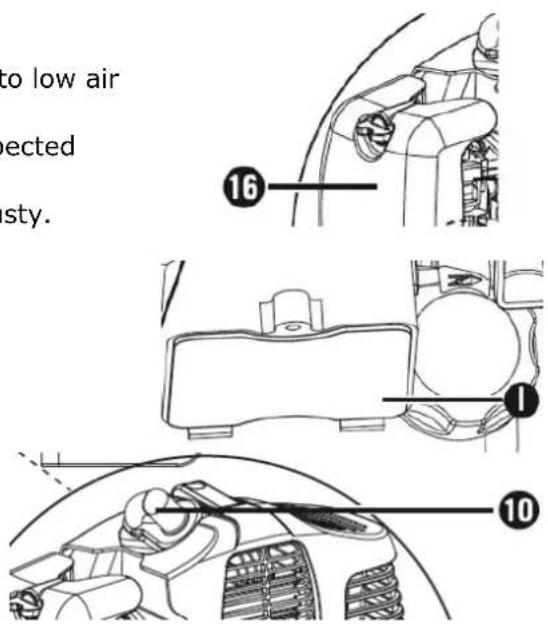
Contaminated air filters reduce the engine performance due to low air supply to the carburettor.
Regular inspection is essential. The air filter (I) must be inspected after every 25 hours of operation and cleaned if necessary.
The air filter must be checked more frequently if the air is dusty.
1.) Remove the cover of the air filter housing (16).
2.) Remove the air filter (I).
3.) Clean the air filter (I) by tapping or blowing it out (with compressed air).
4.) Assembly takes place in the reverse order.
14.1.5 Spark plug
1.) Pull off the spark plug connector (10).
2.) Unscrew the spark plug using the spark plug wrench supplied.
3.) Assembly takes place in the reverse order.
Electrode gap = 0.6 mm (distance between the electrodes between which the ignition spark is generated). Check the spark plug for contamination after the first 10 hours of operation and clean it with a copper wire brush if required. Afterwards, service the spark plug after every 25 hours of operation.
14.1.6 Carburettor
NOTICE
Carburetor adjustments should be carried out only by trained specialist personnel!
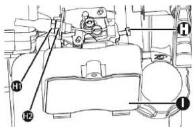
14.1.7 Adjusting the throttle cable
If the appliance no longer reaches maximum speed after a while and all other causes as described in the "Troubleshooting" section have been ruled out, this may mean that the throttle cable needs to be adjusted. To adjust the throttle cable, screw in the screw (H) or the adjusting screw (H1) as well as the lock nut (H2) correctly.
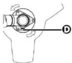
14.1.8 Lubricating the gears
- To do this, undo the screw (D) to press the gear grease into the gear housing.
• After filling the gearbox, close the lubrication hole with the screw (D).
natural_image
Mechanical assembly diagram showing a pipe fitting with directional arrows and a labeled component (D), no text or symbols present.14.2 Replacing the strimmer/cutting strimmer cord
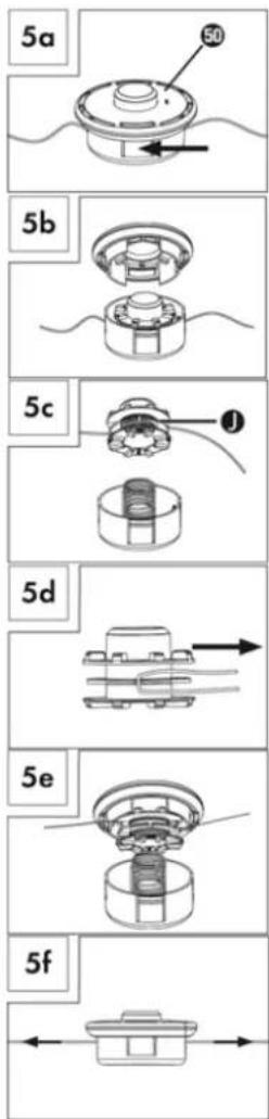
1.) The strimmer (50), is removed as described in the section Installing/ replacing the strimmer. Press the marking (see Fig. 5a), turn the cover and remove one half of the casing (see Fig. 5b).
2.) Remove the spool bobbin (J) from the strimmer housing (see Fig. 5c).
3.) Remove any remaining cutting Strimmer cord.
4.) Double the new cutting Strimmer cord in the middle and hook the loop that you have made into the recess on the spool bobbin (see Fig. 5d).
5.) Wind the Strimmer cord tightly in an anticlockwise direction. The spool bobbin (J) separates the two halves of the cutting Strimmer cord (see Fig. 5d).
6.) Hook the last 15 cm of the two ends of the Strimmer cord into the opposite Strimmer cord holders (J) (see Fig. 5e).
7.) Guide the two ends of the Strimmer cord through the metal lugs in the strimmer housing (see Fig. 5e).
8.) Press the spool bobbin (J) into the strimmer housing (see Fig. 5e).
9.) Reconnect the two halves of the housing.
10.) Pull hard on the two ends of the Strimmer cord to free them from the Strimmer cord holders (see Fig. 5f).
11.) Cut any excess Strimmer cord back to about 13 cm. This reduces the load on the engine when starting and warming up.
12.) Refit the strimmer (see section "Installing/replacing the strimmer"). Skip points 3–6 if you are replacing the entire strimmer.
14.3 Storage
If the machine will be stored longer than 30 days:
• Empty Tank completely, avoid fuel spillage.
• To remove all fuel from the carburettor, start the engine and leave it to run until it stops.
- Let the machine cool down.
- Remove and clean cutting tools.
- Fit the guards
- Clean the machine and dry
• Store in a dry, out of reach of children place, well packaged (protection against cuts)
14.4 Disposal
Do not dispose the machine, machine components fuel and oil in residual waste. Contact your local authorities for information regarding the available disposal options. When you buy at your local dealer for a replacement unit, the latter is obliged to exchange your old.
15 TROUBLE SHOOTING
| Trouble | Possible cause | Solution |
| Engine does not start | Incorrect starting sequence | Observe the correct starting sequence |
| Dirty air filter | Clean/replace air filter | |
| No fuel supply | Refuel | |
| Fault in the fuel line | Check the fuel line for kinks or damages | |
| Engine flooded. | Screw off, clean and dry the spark plug. Then pull the cranking rope several times and reinstall the spark plug | |
| Spark plug connector not placed on. | Place on the spark plug connector | |
| No ignition spark | Clean/replace spark plugCheck ignition cable | |
| Engine starts and is stalled immediately | Incorrect idle adjustment | Contact customer service |
| Machine works with interruptions | Carburetor incorrectly adjusted | Contact customer service |
| Spark plug fouled | Clean/replace spark plugCheck spark plug connector | |
| Smoke | Incorrect fuel mixture (2-stroke engine) | Use correct fuel mixture |
| Carburetor incorrectly adjusted | Contact customer service | |
| Machine does not work with full performance | Machine overloaded | Too much pressureCutting material too tough |
| Dirty air filter | Clean/replace air filter | |
| Carburetor incorrectly adjusted | Contact customer service | |
| Blade rotates at idling | Idle speed too high | Adjust a lower idle speed |
| Blade rotates but has no power | Choke is ON | Set Choke to OFF |
| Bad cuts | Foreign material wrapped, grass around the sheet | Shut machine off, wait until cutter stands still, remove the winded up material |
| Long grass | Remove material | |
| Blunt saw blade | Sharpen or replace saw blade |

NOTICE
Should you in necessary repairs not able to properly to perform or you have not the prescribed training for it always attract a workshop to fix the problem.
16 AVANT-PROPOS (FR)
Cher client, chère cliente,
natural_image
Person wearing a checkered shirt and carrying a device, no visible text or symbols
natural_image
Person wearing a checkered shirt with black safety harnesses and belt, no visible text or symbols
natural_image
Person wearing a full-body safety harness and belt, hands in pockets (no text or symbols visible)
natural_image
Person wearing a checkered shirt and black safety harness, hands adjusting the belt (no text or symbols visible)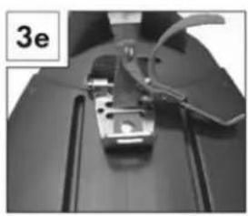
natural_image
Close-up of a sewing machine needle and clasp mechanism (no visible text or symbols)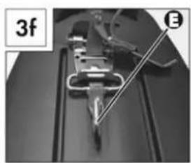
natural_image
Close-up of a mechanical device with a tool and labeled section (3f), no readable text or symbols present.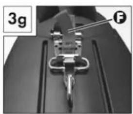
natural_image
Close-up of a mechanical component with a labeled section (3g) and letter (F), no readable text or symbols beyond labels.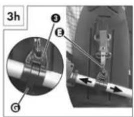
natural_image
Person using a tool on a mechanical component, no visible text or symbols
natural_image
Diagram showing two mechanical or electrical component configurations with cross and check symbols (no text or labels)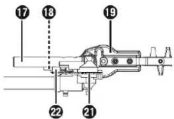


AVIS
natural_image
Technical line drawing of a mechanical device with labeled parts (1c and 69), no readable text or symbols beyond labels

19.4 Taille-haies
natural_image
Technical illustration of a mechanical tool with a handle and circular component, showing assembly or assembly process (no text or symbols)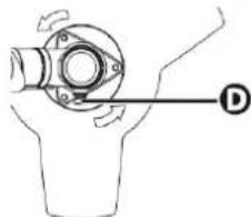
natural_image
Mechanical diagram showing a rotating mechanical component with a labeled point D (no text or symbols present)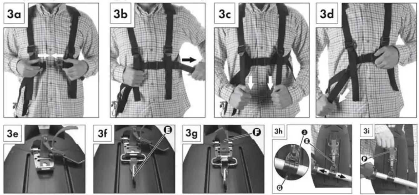
24.1.1 Montaža droga
25.2.2 Topli vžig
1.) Stikalo za VKLOP/IZKLOP (2) dajte na „I”.
2.) Za zagon toplega motorja ne povlecite ročice za zaug (11).
3.) Dobro držite napravo in povlecite zagonsko vrvico (12) do točke odpora. Sedaj hitro povlecite zagonsko vrvico. Naprava se mora zagnati po 1-2 potegih. Če se naprava po 6 potegih še vedno ne zažene, ponovite korake od 1 do 7 v poglavju „Hladni vžig”.
25.4 Škarje za živo mejo
natural_image
Technical illustration of a mechanical tool and its assembly, showing a bracket and a cutting tool (no text or symbols)Žaganje večjih vej:

natural_image
Technical line drawing of a car interior showing steering wheel and dashboard (no text or symbols)NAPOTEK
(EN) With original ZIPPER spare parts you use parts that are attuned to each other shorten the installation time and elongate your machines lifespan.
IMP OR TAN T
The installation of other than original spare parts voids the warranty!
So you always have to use original spare parts
When you place a spare parts order please use the service form you can find in the last chapter of this manual. Always take a note of the machine type, spare parts number and part name. We recommend to copy the spare parts diagram and mark the spare part you need.
You find the order address in the preface of this operation manual.
| N° | Nom | Qty. | N° | Nom | Qty. |
| 1 | 26 throttle handle | 1 | 26 | 9 tooth drive shaft length 780 | 1 |
| 2 | connection plate assy. | 1 | 27 | triangle head gearbox | 1 |
| 3 | screw M5x10 | 1 | 28 | screw M5x14 | 3 |
| 4 | screw M6x30 | 1 | 29 | screw M6x25 | 1 |
| 5 | connect iron | 1 | 30 | nylon trimmer head/2.4mmx6m | 1 |
| 6 | 26 sponge | 2 | 31 | 3T blade | 1 |
| 7 | quick-release liner | 3 | 32 | screw M6x20 | 2 |
| 8 | quick access | 1 | 33 | protective cover plate | 1 |
| 9 | screw M6x25 | 2 | 34 | protective cover | 1 |
| 10 | fast turn knob | 2 | 35 | Protective cover sidebar | 1 |
| 11 | Alu-tube liner | 3 | 36 | screw ST5x12 | 2 |
| 12 | nut M6/thick 6.2 | 2 | 37 | new two holes small blade | 1 |
| 13 | nut M6/thick 5 | 2 | 38 | Alu-tube/26x1.5x640 | 2 |
| 14 | oil bearing | 15 | 39 | 9 tooth drive shaft length 660 | 2 |
| 15 | Alu-tube | 1 | 40 | screw ST3x8 | 1 |
| 16 | toothed ring | 6 | 41 | safe handle | 1 |
| 17 | 9 tooth drive shaft length | 1 | 42 | screw M5x25 | 2 |
| 18 | 26 rings | 1 | 43 | pruner head | 1 |
| 19 | screw M5x20 | 1 | 44 | hedge trimmer head | 1 |
| 20 | 26 hanging rings clip | 1 | 45 | 9 tooth drive shaft length 822 | 1 |
| 21 | nut M5 | 1 | 46 | Alu-tube/26x1.5x810 | 1 |
| 22 | P-type handle | 1 | 47 | quick access | 1 |
| 23 | shafting | 2 | 48 | flat washer 6x16x1.6 | 2 |
| 24 | Alu-tube protective cover | 4 | 49 | steel wire ring/2.0*20mm | 1 |
| 25 | Alu-tube /gear box end | 1 |
Company ZIPPER Maschinen GmbH grants for mechanical and electrical components a warranty period of 2 years for amateur use; and warranty period of 1 year for professional use, starting with the purchase of the final consumer. In case of defects during this period, which are not excluded by paragraph 3, ZIPPER will repair or replace the machine at its own discretion.
2.) Report:
In order to check the legitimacy of warranty claims, the final consumer must contact his dealer. The dealer has to report in written form the occurred defect to ZIPPER. If the warranty claim is legitimate, ZIPPER will pick up the defective machine from the dealer. Returned shippings by dealers which have not been coordinated with ZIPPER, will not be accepted and refused.
3.) Regulations:
a) Warranty claims will only be accepted, when a copy of the original invoice or cash voucher from the trading partner of ZIPPER is enclosed to the machine. The warranty claim expires if the accessories belonging to the machine are missing.
b) The warranty does not include free checking, maintenance, inspection or service works on the machine. Defects due to incorrect usage of the final consumer or his dealer will not be accepted as warranty claims either. Some examples: usage of wrong fuel, frost damages in water tanks, leaving fuel in the tank during the winter, etc.
c) Defects on wear parts are excluded, e.g. carbon brushes, collection bags, knives, cylinders, cutting blades, clutches, sealings, wheels, saw blades, splitting crosses, riving knives, riving knife extensions, hydraulic oils, oil/air/fuel filters, chains, spark plugs, sliding blocks, etc.
d) Also excluded are damages on the machine caused by incorrect or inappropriate usage, if it was used for a purpose which the machine is not supposed to, ignoring the user manual, force majeure, repairs or technical manipulations by not authorized workshops or by the customer himself, usage of non-original ZIPPER spare parts or accessories.
e) After inspection by our qualified personnel, resulted costs (like freight charges) and expenses for not legitimated warranty claims will be charged to the final customer or dealer.
f) In case of defective machines outside the warranty period, we will only repair after advance payment or dealer's invoice according to the cost estimate (incl. freight costs) of ZIPPER.
g) Warranty claims can only be granted for customers of an authorized ZIPPER dealer who directly purchased the machine from ZIPPER. These claims are not transferable in case of multiple sales of the machine.
4.) Claims for compensation and other liabilities:
The liability of company ZIPPER is limited to the value of goods in all cases. Claims for compensation because of poor performance, lacks, damages or loss of earnings due to defects during the warranty period will not be accepted. ZIPPER insists on its right to subsequent improvement of the machine.
32 GARANTIE (FR)
1.) Garantie :
Product experience form
We observe the quality of our delivered products in the frame of a Quality Management policy.
Your opinion is essential for further product development and product choice. Please let us know about your:
- Impressions and suggestions for improvement.
- experiences that may be useful for other users and for product design
- Experiences with malfunctions that occur in specific operation modes
We would like to ask you to note down your experiences and observations and send them to us via FAX, E-Mail or by post:
Erworben von / purchased from:
E-Mail/ e-mail:
Please describe amongst others in the problem: What has cause the problem/defect, what was the last activity before you noticed the problem/defect? For electrical problems: Have you had checked you electric supply and the machine already by a certified electrician?
3. Bitte beachten
/ Additional information
INCOMPLETELY FILLED SERVICE FORMS CANNOT BE PROCESSED! FOR GUARANTEE CLAIMS PLEASE ADD A COPY OF YOUR ORIGINAL SALES / DELIVERY RECEIPT OTHERWISE IT CANNOT BE ACCEPTED. FOR SPARE PART ORDERS PLEASE ADD TO THIS SERVICE FORM A COPY OF THE RESPECTIVE EXPLODED DRAWING WITH THE REQUIRED SPARE PARTS BEING MARKED CLEARLY AND UNMISTAKABLE. THIS HELPS US TO IDENTIFY THE REQUIRED SPARE PARTS FASTLY AND ACCEL- LERATES THE HANDLING OF YOUR INQUIRY.
- INHALT / INDEX / SOMMAIRE
- OPERATION 37
- MAINTENANCE 40
- TROUBLE SHOOTING 43
- AVANT-PROPOS (FR) 44
- Lieferumfang / delivery content / Contenu de la livraison / Vsebina pošiljke
- Technische Daten / technical data / Données techniques / Tehnični podatki
- Warmstart
- Heckenschere
- Hochentaster
- WARNUNG
- Vergaser
- HINWEIS
- Please follow the security instructions!
- Copyright law
- Customer Support
- The machine is used for:
- WARNING
- Ambient conditions
- Prohibited use:
- For the trimmer applies:
- For the hedge trimmer applies:
- For the branch saw applies:
- Safety instructions
- Missing or non-readable security stickers have to be replaced immediately! To avoid malfunction, machine defects and injuries, read the following security instructions!
- TRIMMER:
- BRANCH SAW:
- HEDGE TRIMMER:
- TRANSPORT NOTES:
- STORAGE NOTES:
- Remaining risk factors
- - Risk of injury due to noise:
- - Risk of injury due to the working area:
- - Risk to the hands or fingers:
- - Risk of injury due to pick up and roll up:
- - Risk of burns:
- - Risk of fire and explosion:
- - Chemical risks:
- - Vibration:
- - Kickback:
- ASSEMBLY
- Assembly
- Round handle:
- Quick release mechanism:
- Carrying harness:
- Fitting the boom
- Removing the boom
- Swivelling the hedge trimmer
- Mounting the saw chain and blade
- NOTICE
- Removing the saw chain
- Tightening and checking the saw chain
- Lubricating the chain
- Attaching the boom (extension)
- Fitting/removing the protective guard
- Installing/replacing the cutting blade
- Installing/replacing the strimmer
- OPERATION
- Operation instructions
- Operation
- Cold start
- Warm start
- Switch off the engine
- Trimming / mowing
- Low trimming with strimmer:
- Short mowing with strimmer:
- Extending the cutting Strimmer cord:
- Jamming:
- Hedge trimmer
- Pole pruner
- Sawing off small branches:
- Sawing off larger branches:
- Saw in sections:
- MAINTENANCE
- ATTENTION
- Turn the machine off, disconnect the spark plug and let the machine cool down before performing any maintenance work!
- Cleaning
- Do not use cleaning agents or solvents; these could attack the plastic parts of the machine!
- Cleaning the pole pruner
- Cleaning the hedge trimmer
- Cleaning the strimmer/3-section cutting blade attachment
- Cleaning the air filter
- Spark plug
- Carburettor
- Adjusting the throttle cable
- Lubricating the gears
- Replacing the strimmer/cutting strimmer cord
- Storage
- Disposal
- AVANT-PROPOS (FR)
- Cher client, chère cliente,
- AVIS
- Taille-haies
- Montaža droga
- Topli vžig
- Škarje za živo mejo
- Žaganje večjih vej:
- NAPOTEK
- IMP OR TAN T
- The installation of other than original spare parts voids the warranty!
- 2.) Report:
- 3.) Regulations:
- 4.) Claims for compensation and other liabilities:
- GARANTIE (FR)
- 1.) Garantie :
- Product experience form
- Bitte beachten
- / Additional information
Brand : Zipper
Model : ZIGPS182J
Category : Powered garden tool