HOLLY CADR 65 - Air purifier DAITSU - Free user manual and instructions
Find the device manual for free HOLLY CADR 65 DAITSU in PDF.

User questions about HOLLY CADR 65 DAITSU
0 question about this device. Answer the ones you know or ask your own.
Ask a new question about this device
Download the instructions for your Air purifier in PDF format for free! Find your manual HOLLY CADR 65 - DAITSU and take your electronic device back in hand. On this page are published all the documents necessary for the use of your device. HOLLY CADR 65 by DAITSU.
USER MANUAL HOLLY CADR 65 DAITSU
Thank you for choosing our product.
For proper operation, please read and keep this manual carefully.
If you have lost the Owner's Manual, please contact the local agent or visit sat.eurofredgroup.com.
DS-9UIDN
DS-12UIDN
DS-18UIDN
DS-24UIDN
Content
Operation Notices
Precautions....1
Parts Name....6
ScreenOperation Guide
Remote control operation 7
Emergency operation 11
Maintenance
Clean and Maintenance....11
Malfunction
Malfunction analysis....15
This appliance is not intended for use by persons (including children) with reduced physical, sensory or mental capabilities, or lack of experience and knowledge, unless they have been given supervision or instruction concerning use of the appliance by a person responsible for their safety.
Children should be supervised to ensure that they do not play with the appliance.
This marking indicates that this product should not be disposed with other household wastes throughout the EU. To prevent possible harm to the environment or human health from uncontrolled waste disposal, recycle it responsibly to promote the sustainable reuse of material resources. To return your used device, please use the return and collection systems or contact the retailer where the product was purchased. They can take this product for environmental safe recycling.
R410A(R32/125: 50/50): 2087.5

WARNING
Operation and Maintenance
- This appliance can be used by children aged from 8 years and above and persons with reduced physical, sensory ormental capabilities or lack of experience and knowledge if they have been given supervision or instruction concerning use of the appliance in a safe way and understand the hazards involved.
• Children shall not play with the appliance. - Cleaning and user maintenance shall not be made by children without supervision.
- Do not connect air conditioner to multi-purpose socket. Otherwise, it may cause fire hazard.
- Do disconnect power supply when cleaning air conditioner. Otherwise, it may cause electric shock.
- If the supply cord is damaged, it must be replaced by the manufacturer, its service agent or similarly qualified persons in order to avoid a hazard.
- Do not wash the air conditioner with water to avoid electric shock.
- Do not spray water on indoor unit. It may cause electric shock or malfunction.
• After removing the filter, do not touch fins to avoid injury. - Do not use fire or hair dryer to dry the filter to avoid deformation or fire hazard.

WARNING
- Maintenance must be performed by qualified professionals. Otherwise, it may cause personal injury or damage.
- Do not repair air conditioner by yourself. It may cause electric shock or damage. Please contact dealer when you need to repair air conditioner.
- Do not extend fingers or objects into air inlet or air outlet. It may cause personal injury or damage.
- Do not block air outlet or air inlet. It may cause malfunction.
- Do not spill water on the remote controller, otherwise the remote controller may be broken.
- When below phenomenon occurs, please turn off air conditioner and disconnect power immediately, and then contact the dealer or qualified professionals for service.
- Power cord is overheating or damaged.
- There's abnormal sound during operation.
- Circuit break trips off frequently.
• Air conditioner gives off burning smell. - Indoor unit is leaking.
- If the air conditioner operates under abnormal conditions, it may cause malfunction, electric shock or fire hazard.
- When turning on or turning off the unit by emergency operation switch, please press this switch with an insulating object other than metal.
- Do not step on top panel of outdoor unit, or put heavy objects. It may cause damage or personal injury.

WARNING
Attachment
• Installation must be performed by qualified professionals. Otherwise, it may cause personal injury or damage.
- Must follow the electric safety regulations when installing the unit.
- According to the local safety regulations, use qualified power supply circuit and circuit break.
- Do install the circuit break. If not, it may cause malfunction.
- An all-pole disconnection switch having a contact separation of at least 3mm in all poles should be connected in fixed wiring.
- Including an circuit break with suitable capacity, please note the following table. Air switch should be included magnet buckle and heating buckle function, it can protect the circuit-short and overload.
• Air Conditioner should be properly grounded. Incorrect grounding may cause electric shock.
- Don't use unqualified power cord.
- Make sure the power supply matches with the requirement of air conditioner. Unstable power supply or incorrect wiring or malfunction. Please install proper power supply cables before using the air conditioner.
- Properly connect the live wire, neutral wire and grounding wire of power socket.
- Be sure to cut off the power supply before proceeding any work related to electricity and safety.

WARNING
- Do not put through the power before finishing installation.
- If the supply cord is damaged, it must be replaced by the manufacturer, its service agent or similarly qualified persons in order to avoid a hazard.
- The temperature of refrigerant circuit will be high, please keep the interconnection cable away from the copper tube.
- The appliance shall be installed in accordance with national wiring regulations.
• Installation must be performed in accordance with the requirement of NEC and CEC by authorized personnel only. - The air conditioner is the first class electric appliance. It must be properly grounding with specialized grounding device by a professional. Please make sure it is always grounded effectively, otherwise it may cause electric shock.
- The yellow-green wire in air conditioner is grounding wire, which can't be used for other purposes.
- The grounding resistance should comply with national electric safety regulations.
- The appliance must be positioned so that the plug is accessible.
- All wires of indoor unit and outdoor unit should be connected by a professional.
- If the length of power connection wire is insufficient, please contact the supplier for a new one. Avoid extending the wire by yourself.
WARNING
- For the air conditioner with plug, the plug should be reachable after finishing installation.
- For the air conditioner without plug, an circuit break must be installed in the line.
- If you need to relocate the air conditioner to another place, only the qualified person can perform the work. Otherwise, it may cause personal injury or damage.
- Select a location which is out of reach for children and far away from animals or plants. If it is unavoidable, please add the fence for safety purpose.
- The indoor unit should be installed close to the wall.
Working temperature range
| Indoor side DB/WB (°C) C | Outdoor side DB/WB (°C) | |
| Maximum cooling 32 | /23 43/26 | |
| Maximum heating 27 | /- 24/18 |
NOTICE:
- The operating temperature range (outdoor temperature) for cooling is -15^ 43^ ; Heating temperature range for the model without electric heating belt for chassis is -15^ 24^ Heating temperature range for the model with electric heating belt for chassis is -20^ 24^ .
Indoor Unit
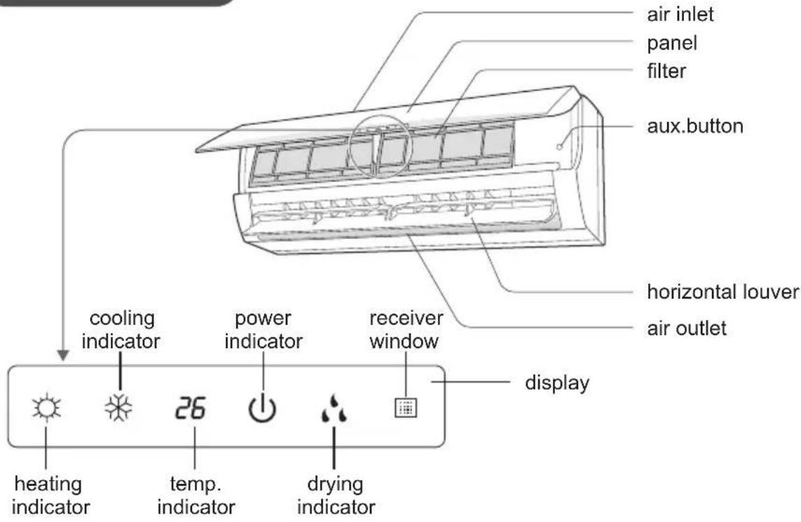
(Display content or position may be different from above graphics, please refer to actual products)
NOTICE:
Actual product may be different from above graphics, please refer to actual products.
Buttons on remote controller
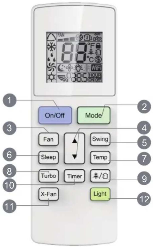
1 On/Off button
2 Mode button
3 Fan button
4 ▲/▼ button
5 Swing button
6 Sleep button
7 Temp button
8 Turbo button
9 / button
10 Timer button
11 X-Fan button
12 Light button
Introduction for buttons on remote controller
NOTICE: "WiFi" This is a general remote controller. Some models have this function while some do not. Please refer to the actual models.
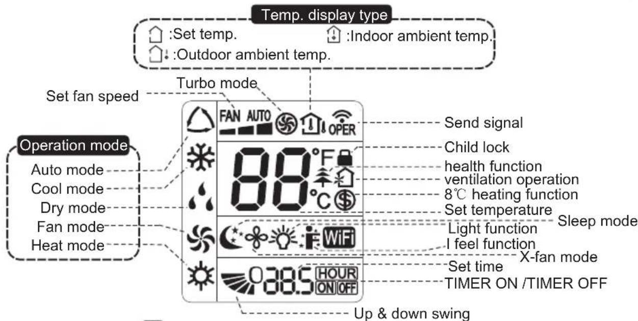
Introduction for buttons on remote controller
Note:
- This is a general use remote controller, it could be used for the air conditioners with multifunction; For some function, which the model doesn't have, if press the corresponding button on the remote controller that the unit will keep the original running status.
- After putting through the power, the air conditioner will give out a sound. Operation indicator "⏻" is ON (red indicator). After that, you can operate the air conditioner by using remote controller.
- Under on status, pressing the button on the remote controller, the signal icon "💡" on the display of remote controller will blink once and the air conditioner will give out a "de" sound, which means the signal has been sent to the air conditioner.
- Under off status, set temperature and clock icon will be displayed on the display of remote controller (If timer on, timer off and light functions are set, the corresponding icons will be displayed on the display of remote controller at the same time); Under on status, the display will show the corresponding set function icons.
1 On/Off button
Press this button to turn on the unit. Press this button again to turn off the unit.
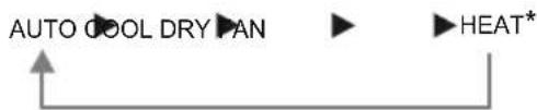
2 Mode button
Each time you press this button, a mode is selected in a sequence that goes from AUTO, COOL, DRY, FAN, and HEAT *, as the following:
flowchart
graph TD
    A["AUTO COOL DRY PAN"] --> B["HEAT*"]
    B --> C["Output Arrow"]
* Note: Only for models with heating function.
3 Fan button
This button is used for setting Fan Speed in the sequence that goes from AUTO, ▲, to ▲, then back to Auto.
4 ▲ / ▼ button
Press ▲ / ▼ button to increase/decreaseset temperature. In AUTO mode, set temperature is not adjustable.
When setting Timer On or Timer Off, press "▲" or "▼" button to adjust the time.
5 Swing button
Press this button to set up & down swing angle.
6 Sleep button
Under Cool, Heat or Dry mode, press this button to turn on Sleep function. Press this button again to cancel Sleep function. Under Fan and Auto modes, this function is unavailable.
Introduction for buttons on remote controller
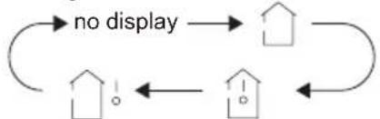
7 Temp button
Press this button, you can see indoor set temperature, indoor ambient temperature on indoor unit's display. The setting on remote controller is selected circularly as below:
flowchart
graph TD
    A["House"] --> B["House"]
    B --> C["House"]
    C --> D["House"]
    D --> A
    style A fill:#f9f,stroke:#333
    style B fill:#ccf,stroke:#333
    style C fill:#cfc,stroke:#333
Note:
- Outdoor temperature display is not available for some models. At that time, indoor unit receives "↑↓" signal, while it displays indoor set temperature.
8 Turbo button
Press this button to activate / deactivate the Turbo function.
9 / button
Press this button to achieve the on and off of healthy and scavenging functions in operation status. Press this button for the first time to start scavenging function; LCD displays "💡". Press the button for the second time to start healthy and scavenging functions simultaneously; LCD displays "💡" and "↑". Press this button for the third time to quit healthy and scavenging functions simultaneously. Press the button for the fourth time to start healthy function; LCD display "↑". Press this button again to repeat the operation above.
- This function is applicable to partial of models.
10 Timer button
- Under ON status, press this button to set timer OFF; Under OFF status, press this button to set timer ON.
- Press this button once and the characters of HOUR ON (OFF) will flash to be displayed. Meanwhile, press "▲" button or "▼" button to adjust timer setting (time will change quickly if holding "▲" or "▼" button). Time setting range is 0.5\~24hours. Press this button again to confirm timer setting and the characters of HOUR ON (OFF)will stop flashing. If the characters are flashing but you haven't press timer button,timer setting status will be quit after 5s.If timer is confirmer, press this button again to cancel timer.
11 X-Fan button
Press this button in COOL or DRY mode to turn on X-fan function.
When this function is started up, indoor fan will still operate at low fan speed for a while after turning off the unit by remote controller.
12 Light button
Press this button to turn on the display's light and press this button again to turn off the display's light.
Function introduction for combination buttons
Combination of "▲" and "▼" buttons: About lock
Press "▲" and "▼" buttons simultaneously 3s to lock or unlock the keypad. If the remote controller is locked, 🔔 is displayed. In this case, pressing any button, 🔔 blinks three times.
Function introduction for combination buttons
Combination of "MODE" and "▼" buttons: About switch between Fahrenheit and centigrade
At unit OFF, press "MODE" and "▼" buttons simultaneously to switch between °C and °F.
Combination of "TEMP" and "TIMER" buttons: About Energy-saving Function
Press "TEMP" and "TIMER" simultaneously in COOL mode to start energy-saving function. Nixie tube on the remote controller displays "SE". Repeat the operation to quit the function.
Combination of "TEMP" and "TIMER" buttons: About 8 °C Heating Function
Press "TEMP" and "TIMER" simultaneously in HEAT mode to start 8°C Heating Function Nixie tube on the remote controller displays " \$ " and a selected temperature of "8°C". (46°F if Fahrenheit is adopted). Repeat the operation to quit the function.
WIFI Function
Press "MODE" and "TURBO" button simultaneously to turn on or turn off WIFI function. When WIFI function is turned on, the "WiFi" icon will be displayed on remote controller; Long press "MODE" and "TURBO" buttons simultaneously for 10s, remote controller will send WIFI reset code and then the WIFI function will be turned on. WIFI function is defaulted ON after energization of the remote controller.
- This function is only available for some models.
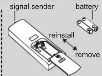
Replacement of batteries in remote controller
-
Press the back side of remote controller marked with "☐", as shown in the fig, and then push out the cover of battery box along the arrow direction.
-
Replace two 7# (AAA 1.5V) dry batteries, and make sure the position of "+" polar and "-" polar are correct.
-
Reinstall the cover of battery box.
Cover of battery box
Emergency operation
If remote controller is lost or damaged, please use auxiliary button to turn on or turn off the air conditioner. The operation in details are as below:
As shown in the g. Open panel, press aux. button to turn on or turn off the air conditioner. When the air conditioner is turned on, it will operate under auto mode.
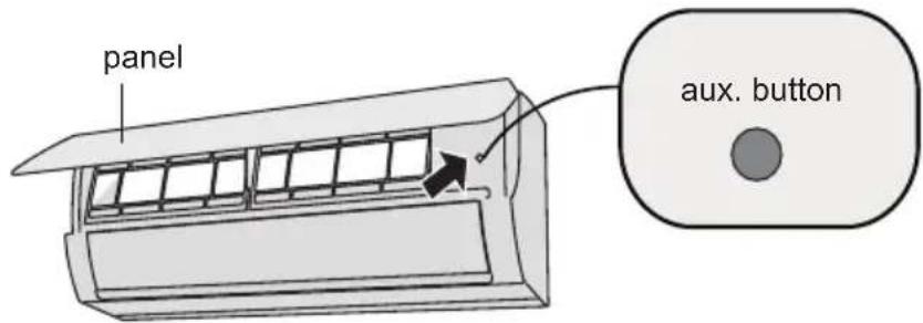

WARNING:
Use insulated object to press the auto button.
Clean and maintenance

WARNING:
■ Turn off the air conditioner and disconnect the power before cleaning the air conditioner to avoid electric shock.
■ Do not wash the air conditioner with water to avoid electric shock.
■ Do not use volatile liquid to clean the air conditioner.
Clean surface of indoor unit
When the surface of indoor unit is dirty, it is recommended to use a soft dry cloth or wet cloth to wipe it.
NOTICE:
- Do not remove the panel when cleaning it.
Clean and maintenance
Clean filter
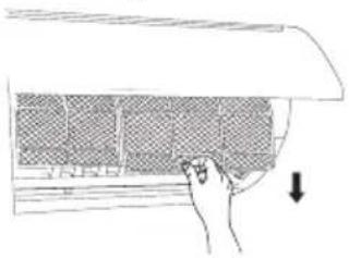
1
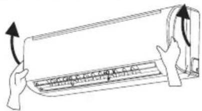
Open panel
Pull out the panel to a certain angle as shown in the fig.
natural_image
Illustration of hands holding a rectangular device with arrows indicating motion or force (no text or symbols)3
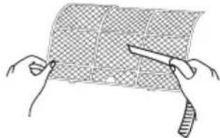
Clean filter
- Use dust catcher or water to clean the filter. - When the filter is very dirty, use the water (below 45^ ) to clean it, and then put it in a shady and cool place to dry.
natural_image
Illustration of hands holding a grid-patterned sheet with scissors (no text or symbols)2
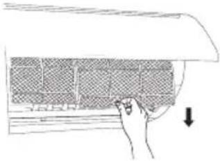
Remove filter
Remove the filter as indicated in the fig.
natural_image
Hand placing a grid on a curved surface with an arrow indicating downward motion (no text or symbols)4
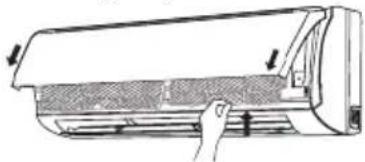
Install filter
Install the filter and then close the panel cover tightly.
natural_image
Diagram of a car air conditioner unit with airflow arrows indicating airflow direction (no text or symbols)
WARNING
■ The filter should be cleaned every three months. If there is much dust in the operation environment, clean frequency can be increased.
■ After removing the filter, do not touch fins to avoid injury.
■ Do not use fire or hair dryer to dry the filter to avoid deformation or fire hazard.
Clean and maintenance
NOTICE: Checking before use-season
- Check whether air inlets and air outlets are blocked.
- Check whether air switch, plug and socket are in good condition.
- Check whether filter is clean.
- Check whether mounting bracket for outdoor unit is damaged or corroded. If yes, please contact dealer.
- Check whether drainage pipe is damaged.
NOTICE: Checking after use-season
- Disconnect power supply.
- Clean filter and indoor unit's panel.
- Check whether mounting bracket for outdoor unit is damaged or corroded. If yes, please contact dealer.
Notice for recovery
- Many packing materials are recyclable materials.
Please dispose them in appropriate recycling unit. - If you want to dispose the air conditioner, please contact local dealer or consultant service center for the correct disposal method.
Malfunction analysis
General phenomenon analysis
Please check below items before asking for maintenance. If the malfunction still can't be eliminated, please contact local dealer or qualified professionals.
| Phenomenon | Check items Solution | |
| Indoor unit can't receive remote controller's signal or remote con-troller has no action. | Whether it's interfered severely (such as static electricity,stable voltage)? | Pull out the plug. Reinsert the plug after about 3 min, and then turn on the unit again. |
| Whether remote controller is within the signal receiving range? | Signal receiving range is 8m. | |
| Whether there are obstacles? | Remove obstacles. | |
| Whether remote controller is pointing at the receiving window? | Select proper angle and point the remote controller at the receiving window on indoor unit. | |
| Is sensitivity of remote controller low; fuzzy display and no display? | Check the batteries. If the power of batteries is too low, please replace them. | |
| No display when operating remote controller? | Check whether remote controller appears to be damaged.If yes, replace it. | |
| Fluorescent lamp in room? | Take the remote controller close to indoor unit.Turn off the fluorescent lamp and then try it again. |
| No air emitted from indoor unit | ● Air inlet or air outlet of indoor unit is blocked? | ● Eliminate obstacles. |
| ● Under heating mode, indoor temperature is reached to set temperature? | ● After reaching to set temperature, indoor unit will stop blowing out air. | |
| ● Heating mode is turned on just now? | ● In order to prevent blowing out cold air, indoor unit will be started after delaying for several minutes, which is a normal phenomenon. |
Malfunction analysis
| Phenomenon | Check items Solution | |
| Air conditioner can't operate | Power failure?Is plug loose?Air switch trips off or fuse is burnt out?Wiring has malfunction?Unit has restarted immediately after stopping operation?Whether the function setting for remote controller is correct? | Wait until power recovery.Reinsert the plug.Ask professional to replace air switch or fuse.Ask professional to replace it.Wait for 3 min, and then turn on the unit again.Reset the function. |
| Mist is emitted from indoor unit's air outlet | Indoor temperature and humidity is high? | Because indoor air is cooled rapidly. After a while, indoor temperature and humidity will be decrease and mist will disappear. |
| Set temperature can't be adjusted | Unit is operating under auto mode?Your required temperature exceeds the set temperature range? | Temperature can't be adjusted under auto mode. Please switch the operation mode if you need to adjust temperature.Set temperature range: 16°C ~30°C. |
| Cooling (heating) effect is not good. | Voltage is too low?Filter is dirty?Set temperature is in proper range?Door and window are open? | Wait until the voltage resumes normal.Clean the filter.Adjust temperature to proper range.Close door and window. |
Malfunction analysis
| Phenomenon | Check items Solution | |
| Odours are emitted | Whether there's odour source, such as furniture and cigarette, etc. | Eliminate the odour source.Clean the filter. |
| Air conditioner operates normally suddenly | Whether there's interference, such as thunder, wireless devices, etc. | Disconnect power, put back power, and then turn on the unit again. |
| Outdoor unit has vapor | Heating mode is turned on? | During defrosting under heating mode, it may generate vapor, which is a normal phenomenon. |
| "Water flowing" noise | Air conditioner is turned on or turned off just now? | The noise is the sound of refrigerant flowing inside the unit, which is a normal phenomenon. |
| Cracking noise | Air conditioner is turned on or turned off just now? | This is the sound of friction caused by expansion and/or contraction of panel or other parts due to the change of temperature. |
Malfunction analysis
Error Code
- When air conditioner status is abnormal, temperature indicator on indoor unit will blink to display corresponding error code. Please refer to below list for identification of error code.
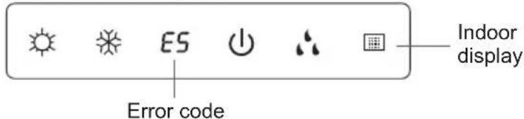
Above indicator diagram is only for reference. Please refer to actual product for the actual indicator and position.
| Error code Troubleshooting | |
| Heating indicator ON 10s OFF 0.5s Means defrosting status. It's the normal phenomenon. | |
| E5: overcurrent protection Power indicator blinks and E5 is displayed | |
| C5: Connector jumper malfunction Check if the connector jumper contacts the properly. If replace the PCB, please take off the old for the new PCB. | |
| F1: Indoor ambient temp. sensor malfunction | Check if indoor room temp. sensor is connected properly? |
| F2: Evaporator temp. sensor malfunction | Check if indoor tube temp. sensor is connected properly? |
| H6: PC motor (indoor fan) can't run | Feedback terminal of PG motor hasn't been connected firmly.The control end of PG motor hasn't been connected firmly.Fan blade hasn't been installed correctly and it can't run smoothly.Motor hasn't been installed correctly and tightly.Motor has been damaged.Control panel has been damaged. |
| U8: Malfunction of zero cross detection circuit for PG motor (indoor fan) | Control panel has been damaged. |
Note:
If there're other error codes, please contact qualified professionals for service.

WARNING
■ When below phenomenon occurs, please turn off air conditioner and disconnect power immediately, and then contact the dealer or qualified professionals for service.
●Power cord is overheating or damaged.
- There's abnormal sound during operation.
●Circuit break trips off frequently.
●Air conditioner gives off burning smell.
- Indoor unit is leaking.
■ Do not repair or refit the air conditioner by yourself
■ If the air conditioner operates under abnormal conditions, it may cause malfunction, electric shock or fire hazard.
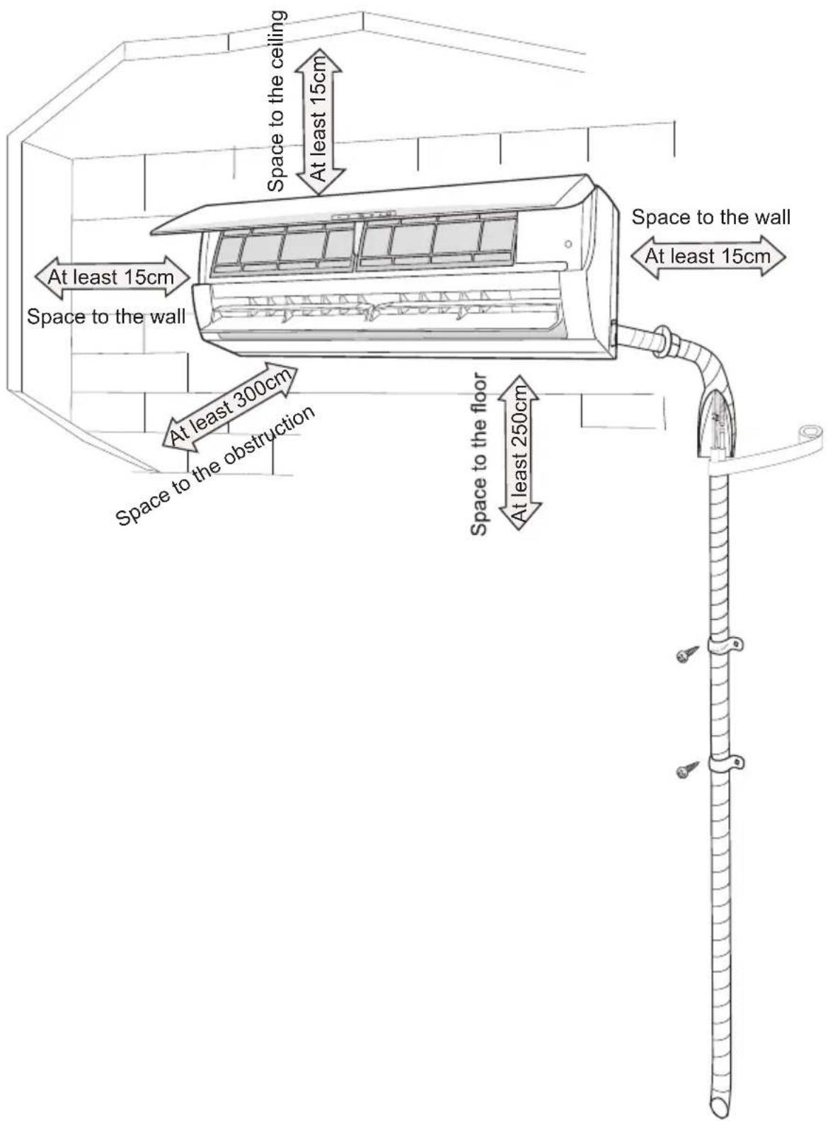
Installation dimension diagram
To ensure safety, please be mindful of the following precautions.
Warning
- When installing or relocating the unit, be sure to keep the refrigerant circuit free from air or substances other than the specified refrigerant.
Any presence of air or other foreign substance in the refrigerant circuit will cause system pressure rise or compressor rupture, resulting in injury.
- When installing or moving this unit, do not charge the refrigerant which is not comply with that on the nameplate or unqualified refrigerant.
Otherwise, it may cause abnormal operation, wrong action, mechanical malfunction or even series safety accident.
- When refrigerant needs to be recovered during relocating or repairing the unit, be sure that the unit is running in cooling mode. Then, fully close the valve at high pressure side (liquid valve). About 30-40 seconds later, fully close the valve at low pressure side (gas valve), immediately stop the unit and disconnect power. Please note that the time for refrigerant recovery should not exceed 1 minute.
If refrigerant recovery takes too much time, air may be sucked in and cause pressure rise or compressor rupture, resulting in injury.
- During refrigerant recovery, make sure that liquid valve and gas valve are fully closed and power is disconnected before detaching the connection pipe. If compressor starts running when stop valve is open and connection pipe is not yet connected, air will be sucked in and cause pressure rise or compressor rupture, resulting in injury.
- When installing the unit, make sure that connection pipe is securely connected before the compressor starts running.
If compressor starts running when stop valve is open and connection pipe is not yet connected, air will be sucked in and cause pressure rise or compressor rupture, resulting in injury.
- Prohibit installing the unit at the place where there may be leaked corrosive gas or flammable gas.
If there leaked gas around the unit, it may cause explosion and other accidents.
- Do not use extension cords for electrical connections. If the electric wire is not long enough, please contact a local service center authorized and ask for a proper electric wire.
Poor connections may lead to electric shock or fire.
- Use the specified types of wires for electrical connections between the indoor and outdoor units. Firmly clamp the wires so that their terminals receive no external stresses.
Electric wires with insufficient capacity, wrong wire connections and insecure wire terminals may cause electric shock or fire.
Tools for installation
| 1 Level meter 2 Screw driver 3 Impact drill | ||
| 4 Drill head 5 Pipe expander 6 Torque wrench | ||
| 7 Open-end wrench 8 Pipe cutter 9 Leakage detector | ||
| 10 Vacuum pump 11 Pressure meter 12 Universal meter | ||
| 13 Inner hexagon spanner 14 Measuring tape | ||
Note:
- Please contact the local agent for installation.
- Don't use unqualified power cord.
Selection of installation location
Basic requirement
Installing the unit in the following places may cause malfunction. If it is unavoidable, please consult the local dealer:
- The place with strong heat sources, vapors, flammable or explosive gas, or volatile objects spread in the air.
- The place with high-frequency devices (such as welding machine, medical equipment).
- The place near coast area.
- The place with oil or fumes in the air.
- The place with sulfureted gas.
- Other places with special circumstances.
- Do not use the unit in the immediate surroundings of a laundry a bath a shower or a swimming pool.
Indoor unit
- There should be no obstruction near air inlet.
- Select a location where the condensation water can be dispersed easily and won't affect other people.
- Select a location which is convenient to connect the outdoor unit and near the power socket.
- Select a location which is out of reach for children.
- The location should be able to withstand the weight of indoor unit and won't increase noise and vibration.
- The appliance must be installed 2.5m above floor.
- Don't install the indoor unit right above the electric appliance.
- Please try your best to keep way from fluorescent lamp.
Requirements for electric connection
Safety precaution
- Must follow the electric safety regulations when installing the unit.
- According to the local safety regulations, use qualified power supply circuit and air switch.
- Make sure the power supply matches with the requirement of air conditioner. Unstable power supply or incorrect wiring or malfunction. Please install proper power supply cables before using the air conditioner.
- Properly connect the live wire, neutral wire and grounding wire of power socket.
- Be sure to cut off the power supply before proceeding any work related to electricity and safety.
- Do not put through the power before finishing installation.
- If the supply cord is damaged, it must be replaced by the manufacturer, its service agent or similarly qualified persons in order to avoid a hazard.
- The temperature of refrigerant circuit will be high, please keep the interconnection cable away from the copper tube.
- The appliance shall be installed in accordance with national wiring regulations.
Grounding requirement
- The air conditioner is the first class electric appliance. It must be properly grounding with specialized grounding device by a professional. Please make sure it is always grounded effectively, otherwise it may cause electric shock.
- The yellow-green wire in air conditioner is grounding wire, which can't be used for other purposes.
- The grounding resistance should comply with national electric safety regulations.
- The appliance must be positioned so that the plug is accessible.
- An all-pole disconnection switch having a contact separation of at least 3mm in all poles should be connected in fixed wiring.
Installation of indoor unit
Step one: choosing installation location
Recommend the installation location to the client and then confirm it with the client.
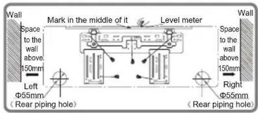
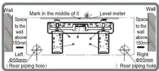
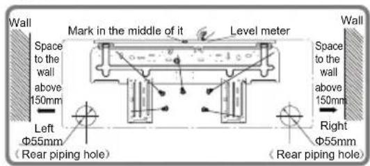
Step two: install wall-mounting frame
- Hang the wall-mounting frame on the wall; adjust it in horizontal position with the level meter and then point out the screw fixing holes on the wall.
- Drill the screw fixing holes on the wall with impact drill (the specification of drill head should be the same as the plastic expansion particle) and then fill the plastic expansion particles in the holes.
- Fix the wall-mounting frame on the wall with tapping screws (ST4.2X25TA) and then check if the frame is firmly installed by pulling the frame. If the plastic expansion particle is loose, please drill another fixing hole nearby.
Step three: open piping hole
- Choose the position of piping hole according to the direction of outlet pipe. The position of piping hole should be a little lower than the wall-mounted frame, shown as below.
07.09K:
12K:
18K:
24K:
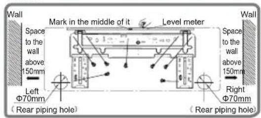
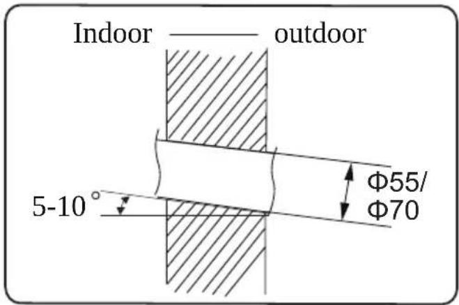
- Open a piping hole with the diameter of 55 or 70 on the selected outlet pipe position. In order to drain smoothly, slant the piping hole on the wall slightly downward to the outdoor side with the gradient of 5 - 10^ .
Installation of indoor unit
Note:
- Pay attention to dust prevention and take relevant safety measures when opening the hole.
- The plastic expansion particles are not provided and should be bought locally.
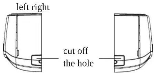
Step four: outlet pipe
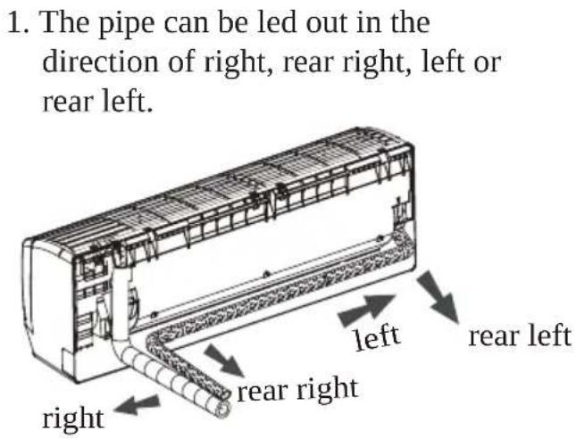
- When select leading out the pipe from left or right, please cut off the corresponding hole on the bottom case.
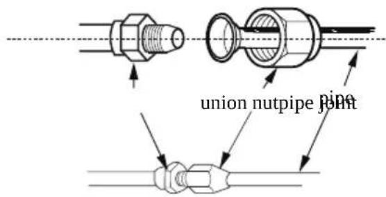
Step five: connect the pipe of indoor unit
-
Aim the pipe joint at the corresponding bellmouth.
-
Pretightening the union nut with hand.
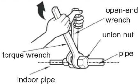
-
Adjust the torque force by referring to the following sheet. Place the open-end wrench on the pipe joint and place the torque wrench on the union nut. Tighten the union nut with torque wrench.
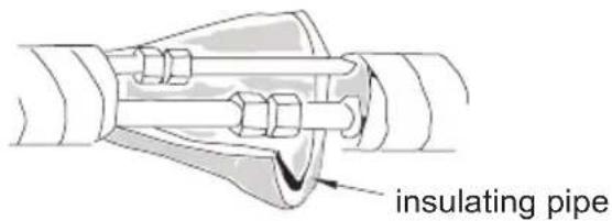
Installation of indoor unit
- Wrap the indoor pipe and joint of connection pipe with insulating pipe, and then wrap it with tape.
| Hex nut diameter | Tightening torque (N ·m) |
| Φ 6 | 15~20 |
| Φ 9.52 | 30~40 |
| Φ 12 | 45~55 |
| Φ 16 | 60~65 |
| Φ 19 | 70~75 |
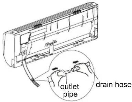
Step six: install drain hose
-
Connect the drain hose to the outlet pipe of indoor unit.
-
Bind the joint with tape.
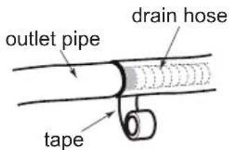
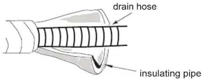
Note:
- Add insulating pipe in the indoor drain hose in order to prevent condensation.
- The plastic expansion particles are not provided.
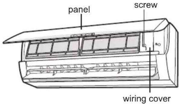
Step seven: connect wire of indoor unit
- Open the panel, remove the screw on the wiring cover and then take down the cover.
Installation of indoor unit
-
Make the power connection wire go through the cable-cross hole at the back of indoor unit and then pull it out from the front side.
-
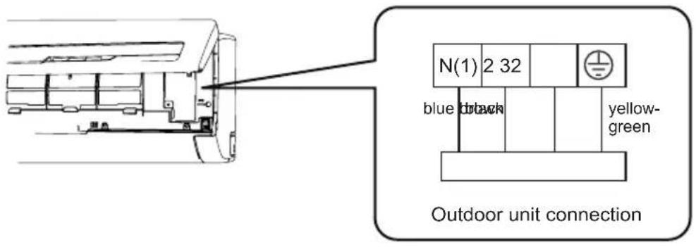
Remove the wire clip; connect the power connection wire to the wiring terminal according to the color; tighten the screw and then fix the power connection wire with wire clip.
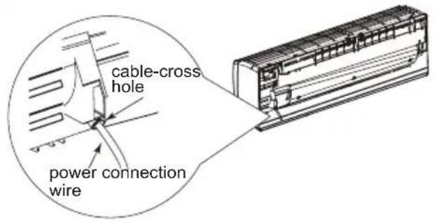
- Put wiring cover back and then tighten the screw.
- Close the panel.
Note:
- All wires of indoor unit and outdoor unit should be connected by a professional.
- If the length of power connection wire is insufficient, please contact the supplier for a new one. Avoid extending the wire by yourself.
- For the air conditioner with plug, the plug should be reachable after finishing installation.
- For the air conditioner without plug, an air switch must be installed in the line. The air switch should be all-pole parting and the contact parting distance should be more than 3mm.
Installation of indoor unit
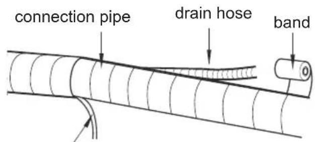
Step eight: bind up pipe
- Bind up the connection pipe, power cord and drain hose with the band.
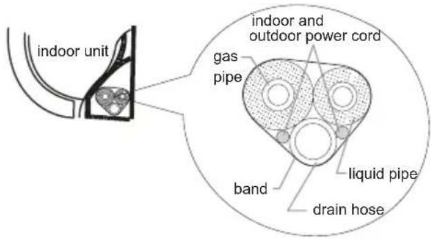
- Reserve a certain length of drain hose and power cord for installation when binding them. When binding to a certain degree, separate the indoor power and then separate the drain hose.
indoor power cord
- Bind them evenly.
- The liquid pipe and gas pipe should be bound separately at the end.
Note:
- The power cord and control wire can't be crossed or winding.
- The drain hose should be bound at the bottom.
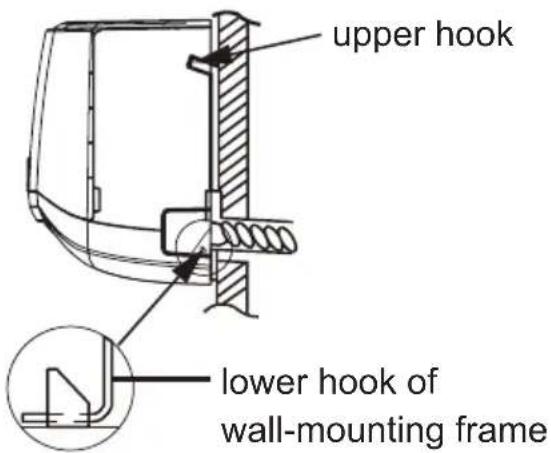
Step nine: hang the indoor unit
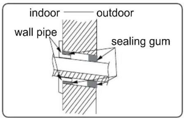
- Put the bound pipes in the wall pipe and then make them pass through the wall hole.
- Hang the indoor unit on the wall-mounting frame.
- Stuff the gap between pipes and wall hole with sealing gum.
- Fix the wall pipe.
- Check if the indoor unit is installed firmly and closed to the wall.
Note:
- Do not bend the drain hose too excessively in order to prevent blocking.
Check after installation
- Check according to the following requirement after finishing installation.
| Items to be checked Possible malfunction | |
| Has the unit been installed firmly? | The unit may drop, shake or emit noise. |
| Have you done the refrigerant leakage test? | It may cause insufficient cooling (heating) capacity. |
| Is heat insulation of pipeline sufficient? | It may cause condensation and water dripping. |
| Is water drained well? | It may cause condensation and water dripping. |
| Is the voltage of power supply according to the voltage marked on the nameplate? | It may cause malfunction or damaging the parts. |
| Is electric wiring and pipeline installed correctly? | It may cause malfunction or damaging the parts. |
| Is the unit grounded securely? It may cause electric leakage. | |
| Does the power cord follow the specification? | It may cause malfunction or damaging the parts. |
| Is there any obstruction in the air inlet and outlet? | It may cause insufficient cooling (heating) capacity. |
| The dust and sundries caused during installation are removed? | It may cause malfunction or damaging the parts. |
| The gas valve and liquid valve of connection pipe are open completely? | It may cause insufficient cooling (heating) capacity. |
| Is the inlet and outlet of piping hole been covered? | It may cause insufficient cooling (heating) capacity or waster electricity. |
Test operation
1. Preparation of test operation
- The client approves the air conditioner.
- Specify the important notes for air conditioner to the client.
2. Method of test operation
- Put through the power, press ON/OFF button on the remote controller to start operation.
- Press MODE button to select AUTO, COOL, DRY, FAN and HEAT to check whether the operation is normal or not.
- If the ambient temperature is lower than 16^ , the air conditioner can't start cooling.
Configuration of connection pipe
- Standard length of connection pipe
- 5m, 7.5m, 8m.
-
Min. length of connection pipe is 3m.
-
Max. length of connection pipe.
| Cooling capacity | Max length of connec-tion pipe |
| 5000Btu/h (1465W) | 15 25 |
| 7000Btu/h (2051W) | 15 30 |
| 9000Btu/h (2637W) | 15 30 |
| 12000Btu/h (3516W) | 20 30 |
| 18000Btu/h (5274W) | 25 30 |
| Cooling capacity | Max length of connection pipe |
| 24000Btu/h (7032W) | |
| 28000Btu/h (8204W) | |
| 36000Btu/h (10548W) | |
| 42000Btu/h (12306W) | |
| 48000Btu/h (14064W) |
- The additional refrigerant oil and refrigerant charging required after prolonging connection pipe
- After the length of connection pipe is prolonged for 10m at the basis of standard length, you should add 5ml of refrigerant oil for each additional 5m of connection pipe.
- The calculation method of additional refrigerant charging amount (on the basis of liquid pipe):
Additional refrigerant charging amount = prolonged length of liquid pipe × additional refrigerant charging amount per meter
- Basing on the length of standard pipe, add refrigerant according to the requirement as shown in the table. The additional refrigerant charging amount per meter is different according to the diameter of liquid pipe. See the following sheet.
Configuration of connection pipe
Additional refrigerant charging amount for R22, R407C, R410A and R134a
| Diameter of connection pipe | Outdoor unit throttle | ||
| Liquid pipe(mm) | Gas pipe(mm) | Cooling only(g/m) | Cooling and heating(g/m) |
| Φ6 | Φ9.52 or Φ12 | 15 | 20 |
| Φ6 or Φ9.52 | Φ16 or Φ19 | 15 | 50 |
| Φ12 | Φ19 or Φ22.2 | 30 | 120 |
| Φ16 | Φ25.4 or Φ31.8 | 60 | 120 |
| Φ19 | - | 250 250 | |
| Φ22.2 | - | 350350 | |
Pipe expanding method
Note:
Improper pipe expanding is the main cause of refrigerant leakage. Please expand the pipe according to the following steps:
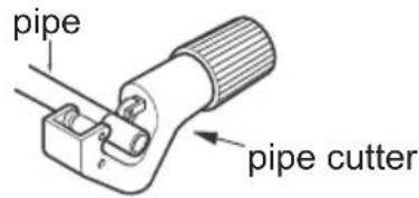
A: Cut the pipe
- Confirm the pipe length according to the distance of indoor unit and outdoor unit.
- Cut the required pipe with pipe cutter.


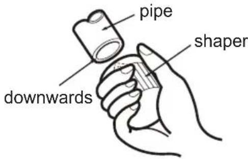
B: Remove the burrs
- Remove the burrs with shaper and prevent the burrs from getting into the pipe.
C: Put on suitable insulating pipe
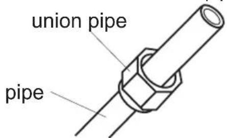
D: Put on the union nut
- Remove the union nut on the indoor connection pipe and outdoor valve; install the union nut on the pipe.
E: Expand the port
- Expand the port with expander.
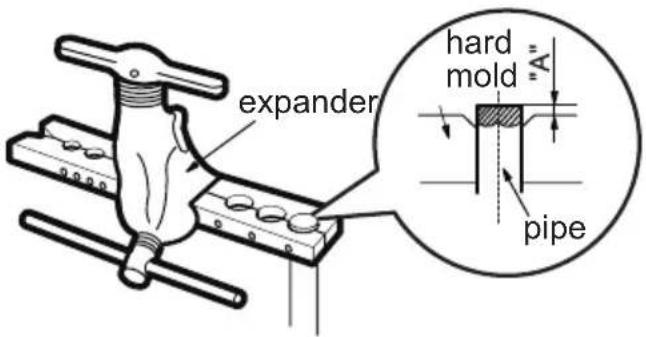
Note:
- "A" is different according to the diameter, please refer to the sheet below:
| Outer diameter (mm) | A(mm) Max Min |
| Φ6 - 6.35(1/4") | 1.3 0.7 |
| Φ9.52(3/8") | 1.6 1.0 |
| Φ12-12.7(1/2") | 1.8 1.0 |
| Φ15.8-16(5/8") | 2.4 2.2 |
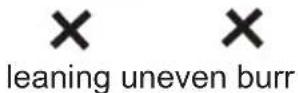
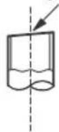
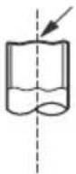
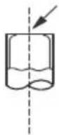
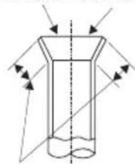
F: Inspection
- Check the quality of expanding port. If there is any blemish, expand the port again according to the steps above.
smooth surface
natural_image
Pure diagram of a cylindrical object with internal flow arrows, no text or symbols presentimproper expanding

leaning

damaged surface

crack uneven
thickness
the length is equal
dzitsu
natural_image
Illustration of hands holding a rectangular device with arrows indicating motion or force (no text or symbols)3
Limpieza del filtro
natural_image
Illustration of two hands holding a grid-patterned sheet with a tool, no text or symbols present2
Retirada del filtro
natural_image
Hand pressing down on a textured surface with a downward arrow (no text or symbols)4
natural_image
Line drawing of a car air conditioner unit with handle and cooling fins (no text or symbols)
ADVERTENCIA
flowchart
graph TD
    A["House Icon"] --> B["House Icon"]
    B --> C["House Icon"]
    C --> D["House Icon"]
    D --> E["House Icon"]
    E --> F["House Icon"]
    F --> G["House Icon"]
    G --> H["House Icon"]
    H --> I["House Icon"]
    I --> J["House Icon"]
    J --> K["House Icon"]
    K --> L["House Icon"]
    L --> M["House Icon"]
    M --> N["House Icon"]
    N --> O["House Icon"]
    O --> P["House Icon"]
    P --> Q["House Icon"]
    Q --> R["House Icon"]
    R --> S["House Icon"]
    S --> T["House Icon"]
    T --> U["House Icon"]
    U --> V["House Icon"]
    V --> W["House Icon"]
    W --> X["House Icon"]
    X --> Y["House Icon"]
    Y --> Z["House Icon"]
Nota:
natural_image
Diagram of hands holding a rectangular device with arrows indicating motion or force (no text or symbols)3
Pulizia del filtro
natural_image
Illustration of hands holding a grid-like object with a tool, no text or symbols present2
Rimuovere il filtro
natural_image
Hand placing a grid pattern into a curved panel with an arrow indicating downward motion (no text or symbols)4
natural_image
Diagram of a car air conditioner unit with hand pressing down (no text or symbols)
ATTENZIONE
flowchart
graph TD
    A["Sem ecră"] --> B["House"]
    B --> C["House"]
    C --> D["House"]
    D --> E["House"]
    E --> F["House"]
    F --> G["House"]
    G --> H["House"]
    H --> I["House"]
    I --> J["House"]
    J --> K["House"]
Nota:

AVISO:
natural_image
Illustration of hands holding a rectangular device with arrows indicating motion or force (no text or symbols)3
Limpar o filtro
natural_image
Illustration of hands holding a grid-patterned fabric or textile with a tool, no text or symbols present2
Remover o filtro
Remova o filtro conforme mostra a fig.
natural_image
Hand holding a grid-patterned object with an arrow indicating downward motion (no text or symbols)4
Instalar filtro
natural_image
Line drawing of a car air conditioner unit with cooling fins and airflow direction arrows (no text or symbols)
AVISO
natural_image
Illustration of a hand holding a cylindrical object with arrows indicating upward motion (no text or symbols)3
Nettoyage du filtre
natural_image
Illustration of hands holding a grid-like object with a tool, no text or symbols present2
natural_image
Hand placing a grid on a wall with an arrow indicating downward motion (no text or symbols)4
Installez le filtre
natural_image
Diagram of a car air conditioner unit with airflow direction arrows (no text or symbols)