517 - Drill Porter-Cable - Free user manual and instructions
Find the device manual for free 517 Porter-Cable in PDF.

| Product Type | Lock Face Template |
| Brand | Porter-Cable |
| Model | 517 |
| Category | Router Accessory |
| Primary Use | Cutting recesses for lock faces on doors |
| Material | Metal and plastic |
| Dimensions (L x W x H) | Approximately 25 cm x 15 cm x 10 cm (estimated) |
| Weight | Approximately 1.5 kg (estimated) |
| Color | Gray and black |
| Included Accessories | Template guide 42024, locknut 42237, straight bit 5/8 in (15.9 mm) (not included but recommended) |
| Main Functions | Precise guidance for router, width and length adjustment of recess |
| Adjustments | Adjustable side guides, adjustable guide bar, locking screws |
| Compatibility | Porter-Cable routers with template guide 42024 |
| Safety | Use safety glasses, disconnect tool before adjustment |
| Maintenance | Clean with a slightly damp soft cloth, do not use solvents |
| Warranty | 1 year (per manufacturer) |
| Country of Manufacture | United States (estimated) |
| General Information | Designed for mortising and routing lock faces quickly and accurately |
Frequently Asked Questions - 517 Porter-Cable
User questions about 517 Porter-Cable
0 question about this device. Answer the ones you know or ask your own.
Ask a new question about this device
Download the instructions for your Drill in PDF format for free! Find your manual 517 - Porter-Cable and take your electronic device back in hand. On this page are published all the documents necessary for the use of your device. 517 by Porter-Cable.
USER MANUAL 517 Porter-Cable
Lock Mortiser and Lock Face Template

natural_image
Mechanical device labeled 'MODEL 513 Mortiser' showing internal components and mounting bracket (no readable text beyond label)MODEL 513 Mortiser
natural_image
Technical line drawing of a mechanical device with no visible text or symbolsMODEL 517 Lock Face Template
IMPORTANT!
Please make certain that the person who is to use this equipment carefully reads and understands these instructions before starting operations.
To learn more about Porter-Cable visit our website at:
http://www.porter-cable.com
PORTER♦CABLE®
The Model and Serial No. plate is located on the main housing of the tool. Record these numbers in the spaces below and retain for future reference.
Model No. ____
Type
Serial No. ____
TABLE OF CONTENTS
IMPORTANT SAFETY INSTRUCTIONS....2
SAFETY GUIDELINES....3
GENERAL SAFETY RULES 4
ADDITIONAL SPECIFIC SAFETY RULES 6
CARTON CONTENTS 8
FUNCTIONAL DESCRIPTION 8
ASSEMBLY 8
OPERATION 9
TROUBLESHOOTING 14
MAINTENANCE....14
SERVICE....15
ACCESSORIES....15
WARRANTY....16
FRANÇAIS....17
ESPAÑOL....33
IMPORTANT SAFETY INSTRUCTIONS
WARNING
Read and understand all warnings and operating instructions before
using any tool or equipment. Always follow basic safety precautions to reduce the risk of personal injury. Improper operation, maintenance, or modification of tools or equipment could result in serious injury and property damage. These tools and equipment are designed for certain applications. DO NOT modify this product and/or use it for any application other than for which it was designed.
If you have any questions relative to its application, DO NOT use the product until you have written Porter-Cable and we have advised you.
Online, contact us at: www.porter-cable.com
By mail, contact us at:
Technical Service Manager
Porter-Cable
4825 Highway 45 North
Jackson, TN 38305
INFORMATION REGARDING SAFE AND PROPER OPERATION IS AVAILABLE FROM:
The Power Tool Institute
1300 Sumner Avenue, Cleveland, OH 44115-2851
www.powertoolinstitute.org
National Safety Council
1121 Spring Lake Drive
Itasca, IL 60143-3201
American National Standards Institute
25 West 43rd Street, 4 floor
New York, NY 10036 www.ansi.org
ANSI 01.1 Safety Requirements for Woodworking Machines
The U.S. Department of Labor regulations
www.osha.gov
SAVE THESE INSTRUCTIONS!
SAFETY GUIDELINES - DEFINITIONS
It is important for you to read and understand this manual. The information it contains relates to protecting YOUR SAFETY and PREVENTING PROBLEMS. The symbols below are used to help you recognize this information.

DANGER
indicates an imminently hazardous situation which, if not avoided, will result in death or serious injury.
WARNING
indicates a potentially hazardous situation which, if not avoided, could result in death or serious injury.
CAUTION
indicates a potentially haz ard ous situation which, if not avoided, may result in minor or moderate injury.
CAUTION
used without the safety alert symbol indicates potentially hazardous situation which, if not avoided, may result in property damage.
CALIFORNIA PROPOSITION 65
WARNING
Some dust created by power sanding, sawing, grinding, drilling, and other construction activities contains chemicals known (to the
State of California) to cause cancer, birth defects or other reproductive harm. Some examples of these chemicals are:
● lead from lead-based paints
● crystalline silica from bricks and cement and other masonry products
● arsenic and chromium from chemically-treated lumber
Your risk from these exposures varies, depending on how often you do this type of work. To reduce your exposure to these chemicals: work in a well ventilated area, and work with approved safety equipment, all ways wear NIOSH/OSHA approved, properly fitting face mask or respi ra tor when using such tools.
GENERAL SAFETY RULES
WARNING
Read all instructions. Failure to follow all instructions listed below may result in electric shock, fire and/or serious injury. The term "power tool" in all of the warnings listed below refers to your mains-operated (corded) power tool or battery-operated (cordless) power tool.

SAVE THESE INSTRUCTIONS
1) Work area safety
a) Keep work area clean and well lit. Cluttered or dark areas invite accidents.
b) Do not operate power tools in explosive atmospheres, such as in the presence of flammable liquids, gases or dust. Power tools create sparks which may ignite the dust or fumes.
c) Keep children and bystanders away while operating a power tool. Distractions can cause you to lose control.
2) Electrical safety
a) Grounded tools must be plugged into an outlet properly installed and grounded in accordance with all codes and ordinances. Never remove the grounding prong or modify the plug in any way. Do not use any adaptor plugs. Check with a qualified electrician if you are in doubt as to whether the outlet is properly grounded. If the tools should electrically malfunction or break down, grounding provides a low resistance path to carry electricity away from the user. Applicable only to Class I (grounded) tools.
b) Double insulated tools are equipped with a polarized plug (one blade is wider than the other.) This plug will fi t in a polarized outlet only one way. If the plug does not fi t fully in the outlet, reverse the plug. If it still does not fi t, contact a qualifi ed electrician to install a polarized outlet. Do not change the plug in any way. Double insulation eliminates the need for the three wire grounded power cord and grounded power supply system. Applicable only to Class II (double insulated) tools.
c) Avoid body contact with earthed or grounded surfaces such as pipes, radiators, ranges and refrigerators. There is an increased risk of electric shock if your body is earthed or grounded.
d) Do not expose power tools to rain or wet conditions. Water entering a power tool will increase the risk of electric shock.
e) Do not abuse the cord. Never use the cord for carrying, pulling or unplugging the power tool. Keep cord away from heat, oil, sharp edges or moving parts. Damaged or entangled cords increase the risk of electric shock.
f) When operating a power tool outdoors, use an extension cord suitable for outdoor use. Use of a cord suitable for outdoor use reduces the risk of electric shock.
3) Personal safety
a) Stay alert, watch what you are doing and use common sense when operating a power tool. Do not use a power tool while you are tired or under the influence of drugs, alcohol or medication. A moment of inattention while operating power tools may result in serious personal injury.
GENERAL SAFETY RULES continued
b) Use safety equipment. Always wear eye protection. Safety equipment such as dust mask, non-skid safety shoes, hard hat, or hearing protection used for appropriate conditions will reduce personal injuries.
c) Avoid accidental starting. Ensure the switch is in the off-position before plugging in. Carrying power tools with your finger on the switch or plugging in power tools that have the switch on invites accidents.
d) Remove any adjusting key or wrench before turning the power tool on. A wrench or a key left attached to a rotating part of the power tool may result in personal injury.
e) Do not overreach. Keep proper footing and balance at all times. This enables better control of the power tool in unexpected situations.
f) Dress properly. Do not wear loose clothing or jewelry. Keep your hair, clothing and gloves away from moving parts. Loose clothes, jewelry or long hair can be caught in moving parts.
g) If devices are provided for the connection of dust extraction and collection facilities, ensure these are connected and properly used. Use of these devices can reduce dust-related hazards.
4) Power tool use and care
a) Do not force the power tool. Use the correct power tool for your application. The correct power tool will do the job better and safer at the rate for which it was designed.
b) Do not use the power tool if the switch does not turn it on and off. Any power tool that cannot be controlled with the switch is dangerous and must be repaired.
c) Disconnect the plug from the power source before making any adjustments, changing accessories, or storing power tools. Such preventive safety measures reduce the risk of starting the power tool accidentally.
d) Store idle power tools out of the reach of children and do not allow persons unfamiliar with the power tool or these instructions to operate the power tool. Power tools are dangerous in the hands of untrained users.
e) Maintain power tools. Check for misalignment or binding of moving parts, breakage of parts and any other condition that may affect the power tools operation. If damaged, have the power tool repaired before use. Many accidents are caused by poorly maintained power tools.
f) Keep cutting tools sharp and clean. Properly maintained cutting tools with sharp cutting edges are less likely to bind and are easier to control.
g) Use the power tool, accessories and tool bits etc., in accordance with these instructions and in the manner intended for the particular type of power tool, taking into account the working conditions and the work to be performed. Use of the power tool for operations different from those intended could result in a hazardous situation.
5) Service
a) Have your power tool serviced by a qualified repair person using only identical replacement parts. This will ensure that the safety of the power tool is maintained.
ADDITIONAL SPECIFIC SAFETY RULES
- Hold tool by insulated gripping surfaces when performing an operation where the cutting tools may contact hidden wiring or its own cord. Contact with a "live" wire will make exposed metal parts of the tool "live" and shock the operator.
- DURATION ate the motor unit unless it is mounted in the lock mortiser carriage.
- Be sure cord is free and will not "hang up" during operations.
- Keep hands clear of cutter when motor is running to prevent personal injury.
- Stay alert and keep cutter clear of all foreign objects while motor is running.
- Be sure motor has completely stopped before withdrawing cutter from machined mortise.
- Accessories must be rated for at least the speed recommended on the tool warning label. Wheels and other accessories running over rated speed can fly apart and cause injury.
- Wear eye and hearing protection. Always use safety glasses. Everyday eyeglasses are NOT safety glasses. USE CERTIFIED SAFETY EQUIPMENT. Eye protection equipment should comply with ANSI Z87.1 standards. Hearing equipment should comply with ANSI S3.19 standards.
- LEAMING tool can generate and disburse dust or other airborne particles, including wood dust, crystalline silica dust and asbestos dust. Direct particles away from face and body. Always operate tool in well ventilated area and provide for proper dust removal. Use dust collection system wherever possible. Exposure to the dust may cause serious and permanent respiratory or other injury, including silicosis (a serious lung disease), cancer, and death. Avoid breathing the dust, and avoid prolonged contact with dust. Allowing dust to get into your mouth or eyes, or lay on your skin may promote absorption of harmful material. Always use properly fitting NIOSH/OSHA approved respiratory protection appropriate for the dust exposure, and wash exposed areas with soap and water.
SYMBOL
| V | volts |
| A | amperes |
| Hz | hertz |
| W | watts |
| kW | kilowatts |
| F | farads |
| μF | microfarads |
| I | litres |
| g | grams |
| kg | kilograms |
| bar | bars |
| Pa | pascals |
| h | hours |
| min | minutes |
| s | seconds |
| n_0 | no-load speed |
| .../min or ...min ^-1 | Revolutions or reciprocations per minute |
| or d.c. | direct current |
| or a.c. | alternating current |
DEFINITION

text_image
2 ~ ....... two-phase alternating current 2N ~ ....... two-phase alternating current with neutral 3 ~ ....... three-phase alternating current 3N ~ ....... three-phase alternating current with neutral ....... rated current of the appropriate fuse-link in amperes ....... time-lag miniature fuse-link where X is the symbol for the time/current characteristic, as given in IEC 60127 ....... protective earth IPXX ....... class II tool ....... IP symbolMOTOR
Many Porter-Cable tools will operate on either D.C., or single phase 25 to 60 cycle A.C. current and voltage within plus or minus 5 percent of that shown on the specification plate on the tool. Several models, however, are designed for A.C. current only. Refer to the specification plate on your tool for proper voltage and current rating.
CAUTION Do not operate your tool on a current on which the voltage is not within correct limits. Do not operate tools rated A.C. only on D.C. current. To do so may seriously damage the tool.
EXTENSION CORD SELECTION
If an extension cord is used, make sure the conductor size is large enough to prevent excessive voltage drop which will cause loss of power and possible motor damage. A table of recommended extension cord sizes will be found in this section. This table is based on limiting line voltage drop to 5 volts (10 volts for 230 volts) at 150% of rated amperes.
If an extension cord is to be used outdoors, it must be marked with the suffix W-A or W following the cord type designation. For example – SJTW-A to indicate it is acceptable for outdoor use.
RECOMMENDED EXTENSION CORD SIZES FOR USE WITH PORTABLE ELECTRIC TOOLS
| Length of Cord in Feet | ||||||||||
| 115V | 25 Ft. | 50 Ft. | 100 Ft. | 150 Ft. | 200 Ft. | 250 Ft. | 300 Ft. | 400 Ft. | 500 Ft. | |
| 230V | 50 Ft. | 100 Ft. | 200 Ft. | 300 Ft. | 400 Ft. | 500 Ft. | 600 Ft. | 800 Ft. | 1000 Ft. | |
| Nameplate Ampere Rating | 0-2 | 18 | 18 | 18 | 16 | 16 | 14 | 14 | 12 | 12 |
| 2-3 | 18 | 18 | 16 | 14 | 14 | 12 | 12 | 10 | 10 | |
| 3-4 | 18 | 18 | 16 | 14 | 12 | 12 | 10 | 10 | 8 | |
| 4-5 | 18 | 18 | 14 | 12 | 12 | 10 | 10 | 8 | 8 | |
| 5-6 | 18 | 16 | 14 | 12 | 10 | 10 | 8 | 8 | 6 | |
| 6-8 | 18 | 16 | 12 | 10 | 10 | 8 | 6 | 6 | 6 | |
| 8-10 | 18 | 14 | 12 | 10 | 8 | 8 | 6 | 6 | 4 | |
| 10-12 | 16 | 14 | 10 | 8 | 8 | 6 | 6 | 4 | 4 | |
| 12-14 | 16 | 12 | 10 | 8 | 6 | 6 | 6 | 4 | 2 | |
| 14-16 | 16 | 12 | 10 | 8 | 6 | 6 | 4 | 4 | 2 | |
| 16-18 | 14 | 12 | 8 | 8 | 6 | 4 | 4 | 2 | 2 | |
| 18-20 | 14 | 12 | 8 | 6 | 6 | 4 | 4 | 2 | 2 | |
SAVE THESE INSTRUCTIONS!
CARTON CONTENTS
* Four height rod sections
* Two cutting bits
* Open end wrench
* Two flat washers
* Two cap screws
* Allen Wrench
* Motor unit
* Mortiser frame
FUNCTIONAL DESCRIPTION
FOREWORD
The Model 513 Lock Mortiser permits builders and contractors to quickly cut true, accurate mortises for door-box locks.
The Model 517 Lock-Face Template allows quick and economical routing for lock faces on doors after the mortise has been completed.
ASSEMBLY
ASSEMBLY TOOLS REQUIRED
Hex wrench (supplied)
ASSEMBLY TIME ESTIMATE
15 to 30 minutes
STANDARD EQUIPMENT
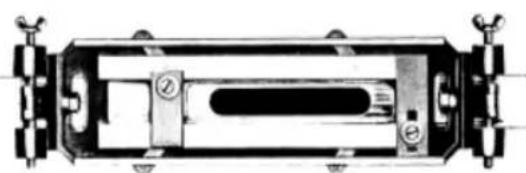
Four sections of the height rod (A), and two bits (B) are furnished (Fig. 1).
text_image
A B Fig. 1ASSEMBLY OF BASE UNIT
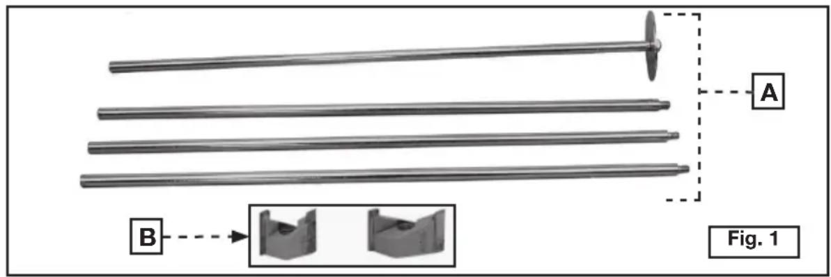
The unit is shipped with the crank handle disassembled.
Remove the bolt and washer (B and C) Fig. 2. Place the crank handle (D) on the crank shaft (A) with the wooden knob facing out and the "D"-shaped hole in handle aligned with the flat on the shaft. Place the bolt (C) through the washer (B) and thread it into the shaft (A). Tighten securely.
text_image
A B C D Fig. 2ASSEMBLY OF MOTOR UNIT
WARNING Disconnect tool from power source!
- In the hardware package, locate the two cap screws, two flat washers, and a 5/32" (4.0 mm) hex wrench. Place the washers on the cap screws.
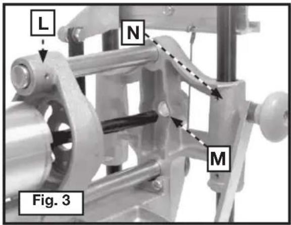
- Insert the splined cutter shaft (Fig. 3) through the motor carriage (L) and into the spiral grooved bushing (M) in the main frame (N). Orient motor as shown in Fig. 8 and seat it into the motor carriage.
- Insert the two screw and washer assemblies (from Step 1) through the motor carriage (Fig. 4). Thread them into the holes in the motor housing. Tighten securely with the hex wrench.
text_image
L N M Fig. 3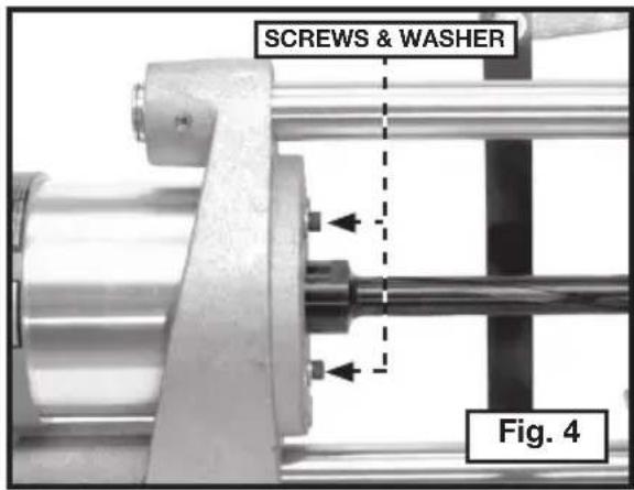
text_image
SCREWS & WASHER Fig. 4OPERATION
DETERMINE WIDTH OF CUT
Measure the width of the lock box at its widest point, including any protruding parts. DO NOT INCLUDE THE LOCK FACE. Select a cutter equal to, or slightly larger than this width.
Example: 1) Overall width of lock box - 31/32" (24.6 mm)
Use PORTER-CABLE #43704PC 1" (25.4 mm) diameter bit.
2) Overall width of lock box - 3/4" (19.1 mm)
Use PORTER-CABLE #43703PC 3/4" (19.1 mm) diameter bit.
Various sizes of bits are available as accessories.
⚠ WARNING DISCONNECT THE TOOL FROM THE POWER SOURCE and exercise extreme care when handling the cutter to avoid bodily injury or damage to the cutting edge.
Thread the selected bit on the end of the splined cutter shaft. Tighten securely.
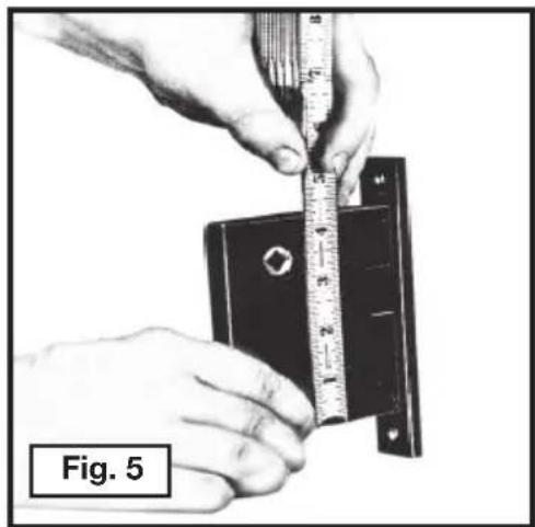
DETERMINING LENGTH OR HEIGHT OF CUT
Measure the height of the lock box (Fig. 5), including any protruding parts. DO NOT INCLUDE THE LOCK FACE.
natural_image
Close-up of hands measuring a black rectangular object with a ruler, labeled 'Fig. 5' (no other text or symbols)SETTING MORTISER FOR LENGTH OF CUT
WARNING Disconnect tool from power source!
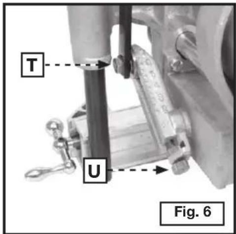
Set the mortiser for the length of cut (Fig. 6). Loosen the crank pin nut (T) and turn the adjusting knob (U) until the correct graduation mark on the slide aligns with the line on the crank-pin indicating washer. If you find that the adjusting knob (U) is difficult to move, turn the crank (E) Fig. 8 until the tension is relieved. Tighten the crank pin nut (T), Fig. 6 securely.
text_image
T U Fig. 6EXAMPLE: If you want your mortise to be 4" (101.6 mm) long, turn the adjusting knob (U) until the Fig. 6 graduation mark aligns with the line on the crank-pin indicating washer.
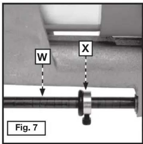
SETTING MORTISER FOR DEPTH OF CUT
WARNING Disconnect tool from power source!
Measure the lock box at its deepest part, including the thickness of the lock face. Add 1/4" (6.4 mm) for clearance. The depth of cut is controlled by the feed rod (W) Fig. 7 which is marked in 1/4" (6.4 mm) increments. Loosen the collar (X) and move it to the determined depth requirement. Lock it in place.
MAKING A TRIAL CUT
After set-up, make a trial cut to ensure the fit of the lock box.
- Clamp a length of 2" x 6" (50.8 x 152.4 mm), or larger lumber in vise, or fasten it securely to a work bench, in an upright position.
⚠ WARNING Disconnect tool from power source!
text_image
W X Fig. 7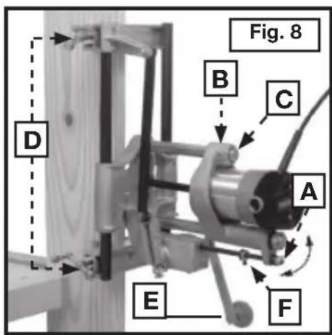
text_image
Fig. 8 B C A D E F- Move the feed lever (A) to the horizontal position (Fig. 8). Pull the motor carriage (B) to the end of the guide rod (C).
- Place the mortiser against the edge of the 2" x 6" so that the clamps are firmly seated. The crank (E) will be free to revolve. Tighten the clamp handles (D) securely to hold the mortiser in position.
- Move the feed lever (A) to the vertical position to engage the feed mechanism.
WARNING Make sure that the motor switch is in the "OFF" position.
- Connect the mortiser to the power source.
- Turn motor switch "ON" and rotate the crank (E) until the collar (F) hits the feed housing, stopping the depth of cut and completing the mortise.
- Turn the motor "OFF".
WARNING Disconnect tool from power source!
-
Move the feed lever (A) to the horizontal position.
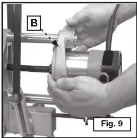
-
Grasp the motor carriage (B) Fig. 9 with both hands and pull toward you until the bit is clear. Remove the mortiser from 2" X 6".
-
Remove all chips from the cut and test the lock box for fit. If necessary, readjust the mortiser and make another trial cut.
natural_image
Close-up of hands operating a mechanical device with labeled parts (B and Fig. 9), no readable text or symbols beyond labels.NOTE: Be sure the length of the mortise cut has not removed the stock required for the two screws that retain the lock box to the door.
MORTISING A DOOR
After you make a successful trial cut, mortise the door.
-
Place the door in an upright position and anchor it securely. If the door is hung, use wedges under the bottom of the door to keep it from moving.
-
Place the lock box against the side of the door at the desired distance from the floor.
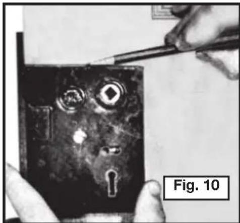
-
Make a mark on the side of the door at the top of the lock box (Fig. 10). Transfer this mark to the front edge of the door.
-
Draw a line 3/8" (9.5 mm) above this mark across the front edge of the door. This is required for clearance for the radius of the cutter.
natural_image
Close-up of hands using tweezers to inspect a dark electronic component with visible internal features (no text or symbols)NOTE: The actual clearance may be determined from the lock box and the trial cut in the 2" X 6". This clearance may be used in place of 3/8" (9.5 mm).
⚠ WARNING Disconnect tool from power source!
- Turn the mortiser crank handle until the bit is in the top-most position.
- Place the mortiser on the door so that the top edge of the bit touches the line drawn on edge of the door.
- Mortise the door as instructed in "MAKING A TRIAL CUT".
PRODUCTION LOCK MORTISING
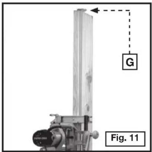
If you have a number of doors with the locks at the same height, the height-rod attachment (Fig. 11) can be of great value. After you have determined the correct height, and have the lock mortiser in position on the first door, attach the four rods that compose the height-rod attachment. Insert the rods in the mortiser and place the height rod stop (G) on the top of the rod so that it rests on the top of the door. Lock the height-rod screws (H) Fig. 12. To locate the mortiser on the next door, place the mortiser on the door with the height-rod stop resting on the top of the door and tighten the clamps. This will assure having all locks located in the same position.
text_image
G Fig. 11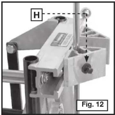
text_image
H Fig. 12MODEL 517 LOCK FACE TEMPLATE
REQUIRED EQUIPMENT (Router and Template)
42024 Template Guide (included)
42237 Locknut (Included)
43440PC 5/8" (15.9 mm) Diameter Straight Bit (not included)
Setting up the template
- Loosen the locking screw (A) Fig. 13.
- Adjust the side guides (C) Fig. 13, so that the space between them is 1/8'' (3.2 mm) wider than the lock face.
- Firmly tighten the screw (A).
- Loosen the locking screw (D) Fig. 13.
- Adjust the distance between (E) and (B) to 1/8" (3.2 mm) longer than the lock face.
- Firmly tighten the screw (D).
LOCATING THE TEMPLATE ON THE DOOR
- Draw a line across the door edge at the center of the mortise cut for the lock.
- Draw a line (F) Fig. 13 on the template side guides (C), midway between bars (B) and (E).
- Position the template on door so that the line (F) on the template matches the line drawn on the door edge at the center of the mortise cut.
- Tighten the two wing screws (G) Fig. 13 to lock the template in place.
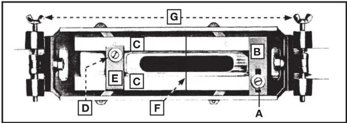
text_image
G C B E C D F APREPARING THE ROUTER
WARNING Disconnect tool from power source!
- Attach the 42024 template guide to the router base with 42237 lock nut.
- Install a bit in the router collet.
- Set the router on the lock face template. Adjust the depth of cut so that the bit just touches the door.
- Set the router-depth adjusting ring to the zero position.
- Lift the router from the template. Adjust the depth-of-cut equal to the thickness of the lock face.
- Firmly tighten the motor-locking device.
MAKING THE CUT
WARNING Make sure router switch is in the "OFF" position.
- Connect the router cord to the power source.
- Mortise the door for the lock face, guiding the router by keeping the template guide against the template guide bars.
- A corner chisel 42234 is available as an accessory for squaring the corners for the lock face.
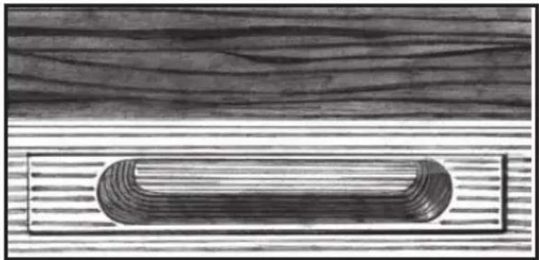
FINISHED MORTISE
The completed mortise is illustrated in Fig. 14. The cut is smooth and even and you can insert the lock box with no further hand work. In Fig. 14, the lock face template has been used and the corner chisel has squared the corners, assuring a perfect fit.
natural_image
Cross-sectional view of a wooden plank with a curved internal structure (no text or symbols)TROUBLESHOOTING
For assistance with your tool, visit our website at www.porter-cable.com for a list of service centers, or call the Porter-Cable Customer Care Center at (888)-848-5175.
MAINTENANCE
KEEP TOOL CLEAN
Periodically blow out all air passages with dry compressed air. All plastic parts should be cleaned with a soft damp cloth. NEVER use solvents to clean plastic parts. They could possibly dissolve or otherwise damage the material.
⚠ WARNING Wear ANSI Z87.1 safety glasses while using compressed air.
FAILURE TO START
Should your tool fail to start, check to make sure the prongs on the cord plug are making good contact in the outlet. Also, check for blown fuses or open circuit breakers in the line.
LUBRICATION
This tool has been lubricated with a sufficient amount of high grade lubricant for the life of the unit under normal operating conditions. No further lubrication is necessary.
BRUSH INSPECTION (If applicable)
For your continued safety and electrical protection, brush inspection and replacement on this tool should ONLY be performed by an AUTHORIZED PORTER-CABLE SERVICE STATION or a PORTER-CABLE• DELTA FACTORY SERVICE CENTER.
At approximately 100 hours of use, take or send your tool to your nearest authorized Porter-Cable Service Station to be thoroughly cleaned and inspected. Have worn parts replaced and lubricated with fresh lubricant. Have new brushes installed, and test the tool for performance.
Any loss of power before the above maintenance check may indicate the need for immediate servicing of your tool. DO NOT CONTINUE TO OPERATE TOOL UNDER THIS CONDITION. If proper operating voltage is present, return your tool to the service station for immediate service.
SERVICE
REPLACEMENT PARTS
Use only identical replacement parts. For a parts list or to order parts, visit our website at servicenet.porter-cable.com. You can also order parts from your nearest factory-owned branch, or by calling our Customer Care Center at 1-888-848-5175 to receive personalized support from highly-trained technicians.
SERVICE AND REPAIRS
All quality tools will eventually require servicing and/or replacement of parts. For information about Porter-Cable, its factory-owned branches, or an Authorized Warranty Service Center, visit our website at www.porter-cable.com or call our Customer Care Center at (888)-848-5175. All repairs made by our service centers are fully guaranteed against defective material and workmanship. We cannot guarantee repairs made or attempted by others.
You can also write to us for information at PORTER-CABLE, 4825 Highway 45 North, Jackson, Tennessee 38305 - Attention: Product Service. Be sure to include all of the information shown on the nameplate of your tool (model number, type, serial number, etc.).
ACCESSORIES
A complete line of accessories is available from your Porter-Cable•Delta Supplier, Porter-Cable•Delta Factory Service Centers, and Porter-Cable Authorized Service Stations. Please visit our Web Site www.porter-cable.com for a catalog or for the name of your nearest supplier.
WARNING
Since accessories other than those offered by Porter-Cable•Delta have not been tested with this product, use of such accessories
could be hazardous. For safest operation, only Porter-Cable•Delta recommended accessories should be used with this product.
WARRANTY
To register your tool for warranty service visit our website at www.porter-cable.com
PORTER-CABLE LIMITED ONE YEAR WARRANTY
Porter-Cable warrants its Professional Power Tools for a period of one year from the date of original purchase. We will repair or replace at our option, any part or parts of the product and accessories covered under this warranty which, after examination, proves to be defective in workmanship or material during the warranty period. For repair or replacement return the complete tool or accessory, transportation prepaid, to your nearest Porter-Cable Service Center or Authorized Service Station. Proof of purchase may be required. This warranty does not apply to repair or replacement required due to misuse, abuse, normal wear and tear or repairs attempted or made by other than our Service Centers or Authorized Service Stations.
ANY IMPLIED WARRANTY, INCLUDING THE IMPLIED WARRANTIES OF MERCHANTABILITY AND FITNESS FOR A PARTICULAR PURPOSE, WILL LAST ONLY FOR ONE (1) YEAR FROM THE DATE OF PURCHASE.
To obtain information on warranty performance please write to: PORTER-CABLE, 4825 Highway 45 North, Jackson, Tennessee 38305; Attention: Product Service. THE FOREGOING OBLIGATION IS PORTER-CABLE'S SOLE LIABILITY UNDER THIS OR ANY IMPLIED WARRANTY AND UNDER NO CIRCUMSTANCES SHALL PORTER-CABLE BE LIABLE FOR ANY INCIDENTAL OR CONSEQUENTIAL DAMAGES. Some states do not allow limitations on how long an implied warranty lasts or the exclusion or limitation of incidental or consequential damages, so the above limitation or exclusion may not apply to you.
This warranty gives you specific legal rights and you may also have other legal rights which vary from state to state.
natural_image
Mechanical assembly model labeled 'MODELO 513' showing internal components and mounting brackets (no readable text beyond label)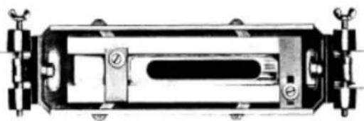
natural_image
Technical line drawing of a mechanical device with mounting flanges and internal components (no text or symbols)MODELO 517 Plantilla de Cerradura
IMPORTANT!
Copyright © 2005 Porter-Cable
INSTRUCTIONS DE SÛRETÉ IMPORTANTES
AVERTISSEMENT
Courrier Postal Technical Service Manager
Porter-Cable
4825 Highway 45 North
Jackson, TN 38305
The Power Tool Institute
1300 Sumner Avenue, Cleveland, OH 44115-2851
www.powertoolinstitute.org
National Safety Council
1121 Spring Lake Drive
Itasca, IL 60143-3201
American National Standards Institute
25 West 43rd Street, 4 floor
New York, NY 10036 www.ansi.org
ANSI 01.1 Safety Requirements for Woodworking Machines
The U.S. Department of Labor regulations
www.osha.gov
MESURES DE SÉCURITÉ - DÉFINITIONS
CONSERVEZ CES INSTRUCTIONS!
CONTENUS DE BOITE
natural_image
Close-up of hands measuring a metal bracket with a ruler, labeled 'Fig. 5' (no other text or symbols)RÉGLAGE DE LA MORTAISEUSE POUR LA LONGUEUR DE LA COUPE
AVERTISSEMENT
Débranchez l'outil.
text_image
W X Fig. 7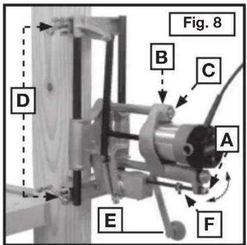
text_image
Fig. 8 D B C A E Fnatural_image
Close-up of hands operating a mechanical device with labeled parts (B and Fig. 9), no readable text or symbols beyond labels.natural_image
Close-up of hands using tweezers to inspect a dark electronic component with visible internal features (no text or symbols)text_image
G C B E C D F APRÉPARATION DE LA TOUPIE
natural_image
Illustration of a wooden plank with concentric grooves, resting on a striped surface (no text or symbols)DEPANNAGE
GARANTIE LIMITÉE D'UN AN OFFERTE PAR PORTER-CABLE
natural_image
Mechanical assembly device labeled 'MODELO 513' (no other text or symbols visible)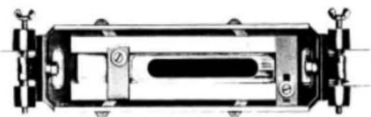
natural_image
Technical line drawing of a mechanical component with no visible text or symbolsMODELO 517 Plantilla de Cerradura
¡IMPORTANTE!
Copyright © 2006 Porter-Cable
El Correo Postal: Technical Service Manager - Porter-Cable
4825 Highway 45 North
Jackson, TN 38305
Power Tool Institute
1300 Sumner Avenue, Cleveland, OH 44115-2851
www.powertoolinstitute.org
National Safety Council
1121 Spring Lake Drive, Itasca, IL 60143-3201
American National Standards Institute
25 West 43rd Street, 4 floor
New York, NY 10036 www.ansi.org
ANSI 01.1 Safety Requirements for Woodworking Machines
The U.S. Department of Labor regulations www.osha.gov
natural_image
Close-up of hands measuring a metal bracket with a ruler, labeled 'Fig. 5' (no other text or symbols)PARA AJUSTAR LA ESCOPLEADORA AL LARGO DEL CORTE
text_image
W X Fig. 7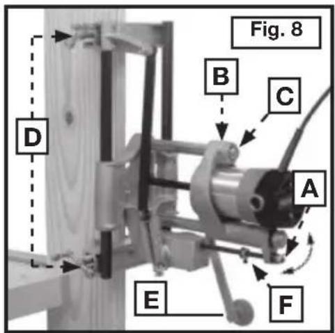
text_image
Fig. 8 D B C A E Fnatural_image
Close-up of hands operating a mechanical device with labeled parts (B and Fig. 9), no readable text or symbols beyond labels.natural_image
Close-up of hands applying adhesive to a dark, textured surface with circular highlights and a keyhole (no text or symbols visible)text_image
G C B E C D F Anatural_image
Cross-sectional view of a wooden plank with concentric grooves and horizontal stripes (no text or symbols)The following are trademarks of PORTER-CABLE • DELTA (Las siguientes son marcas registradas de PORTER-CABLE • DELTA S.A.) (Les marques suivantes sont des marques de fabriquant de la PORTER-CABLE • DELTA): Auto-Set®, BAMMER®, B.O.S.S.®, Builder's Saw®, Contractor's Saw®, Contractor's Saw II™, Delta®, DELTACRAFT®, DELTAGRAM™, Delta Series 2000™ DURATRONICTM, Emc2™, FLEX®, Flying Chips™, FRAME SAW®, Grip Vac™, Homecraft®, Jet-Lock®, JETSTREAM®, 'kickstand®, LASERLOC®, MICRO-SET®, Micro-Set®, MIDI LATHE®, MORTENTM, NETWORK™, OMNIJIG®, POCKET CUTTER®, PORTA-BAND®, PORTA-PLANE®, PORTER-CABLE®&(design), PORTER-CABLE®PROFESSIONAL POWER TOOLS, PORTER-CABLE REDEFINING PERFORMANCE™, Posi-Matic®, Q-3®&(design), QUICKSAND®&(design), QUICKSET™, QUICKSET II®, QUICKSET PLUS™, RIPTIDE™&(design), SAFE GUARD II®, SAFE-LOC®, Sanding Center®, SANDTRAP®&(design), SAW BOSS®, Sawbuck™, Sidekick®, SPEED-BLOC®, SPEEDMATIC®, SPEEDTRONIC®, STAIR EASE®, The American Woodshop®&(design), The Lumber Company®&(design), THE PROFESSIONAL EDGE®, THE PROFESSIONAL SELECT®, THIN-LINE™, TIGER®, TIGER CUB®, TIGER SAW®, TORQBUSTER®, TORQ-BUSTER®, TRU-MATCH™, TWIN-LITE®, UNIGUARD®, Unifence®, UNIFEEDER™, Unihead®, Uniplane™, Unirip®, Unisaw®, Univise®, Versa-Feeder®, VERSA-PLANETM, WHISPER SERIES®, WOODWORKER'S CHOICE™.
4825 Highway 45 North
Jackson, TN 38305
(888)-848-5175
www.porter-cable.com