Flowclear 58647 - Pump BESTWAY - Free user manual and instructions
Find the device manual for free Flowclear 58647 BESTWAY in PDF.
| Brand | Bestway |
| Model | Flowclear 58647 |
| Product type | Filter pump for above-ground pool |
| Usage | Above-ground pools (storable) only |
| Thermal protection | Yes (thermally protected motor) |
| Electrical protection | Residual current device (RCD) required |
| Power supply | 220-240 V ~ 50 Hz (grounded outlet) |
| Fixation base dimensions | 390 x 250 mm (9 mm holes spaced 163 mm apart) |
| Minimum base weight | 18 kg |
| Filter cartridge | Replaceable (recommended replacement every 2 weeks) |
| Storage temperature | 10 °C to 38 °C |
| Compatibility | Above-ground pools only (not for in-ground pools) |
| Safety distance from electrical outlets | At least 1.8 m from the pool |
| Use when swimmers are present | Prohibited |
| Installation | On flat, solid surface, at the same level as the pool base |
| Maintenance | Unplug before any operation |
| Dry operation | Not allowed (risk of damage) |
| Power cord | Do not bury, do not use extension cord |
| Grounding | Required (do not remove ground prong) |
| Spare parts and support | Available at bestwaycorp.com/support |
| Warranty | See bestwaycorp.com |
Frequently Asked Questions - Flowclear 58647 BESTWAY
User questions about Flowclear 58647 BESTWAY
0 question about this device. Answer the ones you know or ask your own.
Ask a new question about this device
Download the instructions for your Pump in PDF format for free! Find your manual Flowclear 58647 - BESTWAY and take your electronic device back in hand. On this page are published all the documents necessary for the use of your device. Flowclear 58647 by BESTWAY.
USER MANUAL Flowclear 58647 BESTWAY
text_image
bestwaycorp.com/supportOWNER'S MANUAL
bestwaycorp.com/support
Visit the Bestway YouTube channel YouTube

text_image
Visit www.bestwaycorp.com/support for help WE SUGGEST NOT TO RETURN THE PRODUCT TO THE STORE QUESTIONS? PROBLEMS? MISSING PARTS? For FAQ, Manuals, Videos Or Spare Parts, Please Visit bestwaycorp.com/supportOWNER'S MANUAL
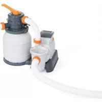
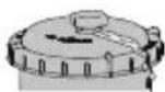
58390/58647 Filter Pump
YouTube
Visit the Bestway YouTube channel
IMPORTANT SAFETY INSTRUCTIONS
READ AND FOLLOW ALL INSTRUCTIONS
Carefully read, understand, and follow all information in this user manual before installing and using the Filter Pump. These warnings, instructions, and safety guidelines address some common risks of water filtration systems, but they cannot cover all risks and dangers in all cases. Always use caution, common sense, and good judgment when enjoying any water activity. Retain this information for future use. In addition, the following information can be supplied depending on the Filter Pump type. Keep the instructions in a safe place. If instruction is missing, search it on the website www.bestwaycorp.com/support.
WARNING
- Thermally protected motor csa enclosure 3.
- For use with swimming pools only.
- CAUTION: To ensure continued protection against shock hazard, use only identical replacement parts when servicing.
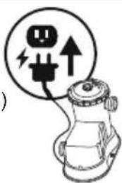
- WARNING: Risk of electric shock. connect only to a grounding type receptacle protected by a ground-fault circuit interrupter (GFCI).
- CAUTION: This pump is for use with storable pools only - do not use with permanently-installed pools.
- CAUTION: Connect only to grounding type receptacle protected by a class a ground fault circuit interrupter.
- CAUTION: For continued protection against possible electric shock this unit is to be mounted to the base in accordance with the installation instructions.
TECHNICAL SAFETY INSTRUCTIONS
- Risk of electric shock, the pump cannot be using while people are inside the pool.
• To reduce the risk of injury, do not permit children to use this product unless they are closely supervised at all times. - To reduce the risk of electric shock the pool must be installed no closer than 6 feet (1.8 m) from any electrical outlet. Do not place portable appliances closer than 5 feet (1.5 m) from the pool.
- Do not bury cord. Locate cord to minimize abuse from lawn mowers, hedge trimmers, and other equipment.
- To reduce the risk of electric shock, replace damaged cord immediately. If the supply cord is damaged, it must be replaced by the manufacturer, its service agent or similarly qualified persons in order to avoid a hazard.
- To reduce the risk of electric shock, do not use extension cord to connect unit to electric supply; provide a properly located outlet.
- This pump is for use with storable pools only. Do not use with permanently-installed pools. A storable pool is constructed so that it is capable of being readily disassembled for storage and reassembled to its original integrity. A permanently-installed pool is constructed in or on the ground or in a building such that it cannot be readily disassembled for storage.
- For continued protection against possible electric shock this unit is to be mounted to the base in accordance with the installation instructions.
- Using the pump with an unmatched electrical supply is dangerous and will result in catastrophic failure of pump.
- When working with electricity, turn the electrical power off at the circuit breaker and lock breaker door. Failure to do so will result in increased risk of shock, injury and possibly death.
- Do not remove the grounding prong or modify the plug in any way. Do not use adapter plugs. Consult a qualified electrician for any questions related to the validity of your plug's grounding.
- Handle the pump with care. Do not pull or carry the pump by the power cord. Never pull a plug from the outlet by yanking the power cord. Keep cord free from abrasions. Sharp objects, oil, moving parts, and heat should never be exposed to the filter pump.
• Atmospheric conditions may affect the performance and life span of your filter pump. Unnecessary wear and tear that may occur during periods of cold, heat and exposure to sun. Whenever possible, shelter the pump from these conditions. - Do not add chemicals in the filter pump.
- Assembly and disassembly by adults only.
• Electric installations should follow national wiring rules, consult a qualified electrician with any questions.
SAVE THESE INSTRUCTIONS
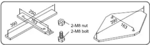
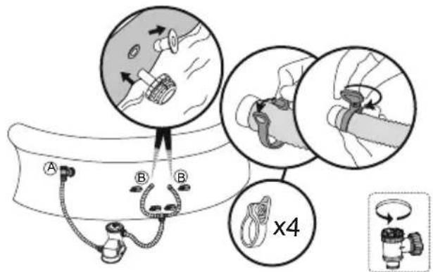
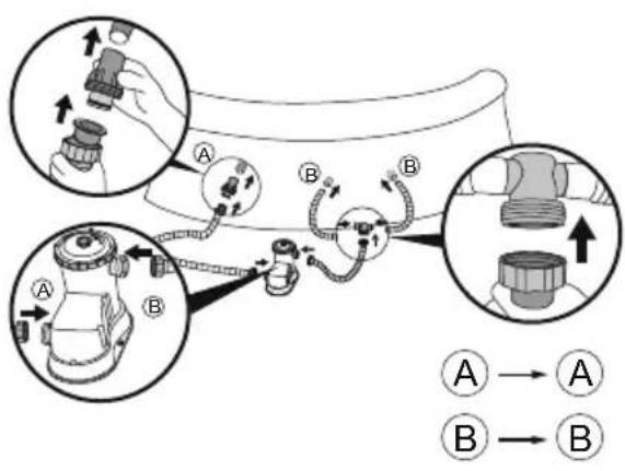
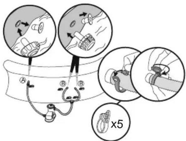
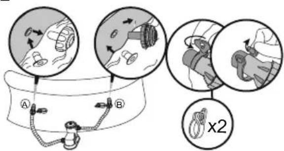
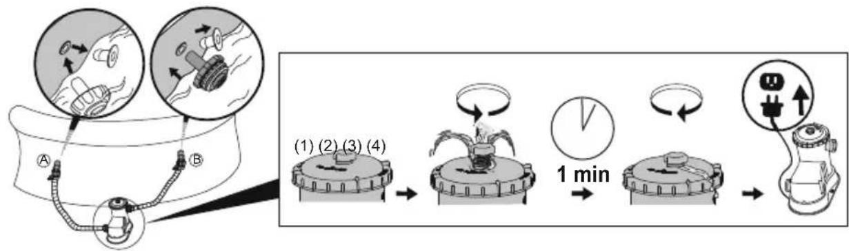
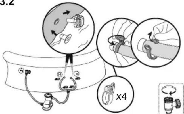
ATTACHING A BASE
The filter pump must be vertically fixed on the ground or a base made of wood or concrete before use. There should be two holes 9mm in diameter on the base, the space between which should be 163mm. Put filter pump on the base and attach them together by fastening the bolts and nuts. All the base parts should weigh at least over 18kg to prevent the pump from accidentally falling.
text_image
250 390 163 40 2-M8 nut 2-M8 bolt 390 163SETUP
CHECK LIST
To check the parts included in the box, consult the part list inside this manual. Verify that the equipment components represent the model that you had intended to purchase. In case of any damaged or missing parts at the time of purchase, visit our website bestwaycorp.com/support.
CHOOSE THE CORRECT LOCATION
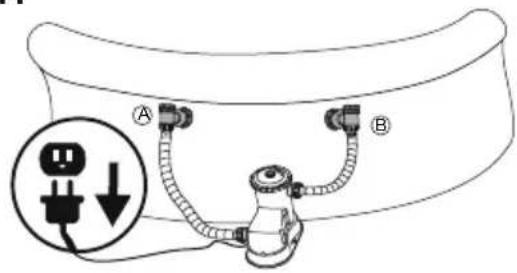
Place the Filter Pump on a solid and level ground; it must be positioned on the same level as the base of the pool. If the Filter Pump is in an upper or lower position than the base of the pool, the performance and life span of the Filter Pump can be compromised. The pool and the Filter Pump have to be positioned in an area with adequate drainage and easy access for maintenance operations. Never place the Filter Pump in a area that may accumulate water.
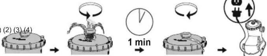
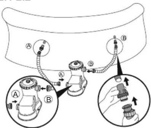
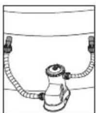
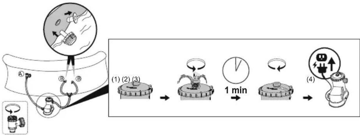
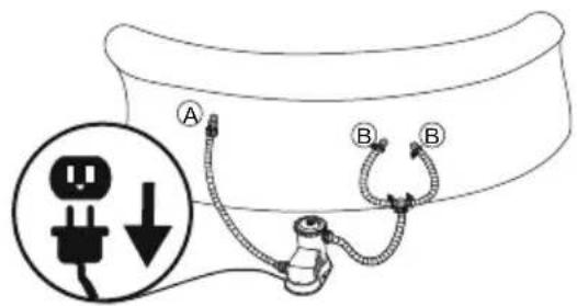
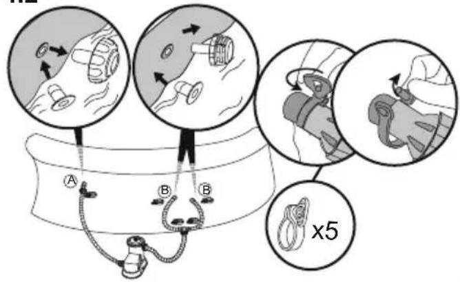
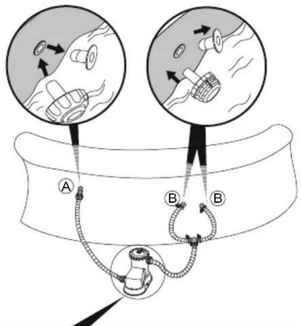
INSTALLATION
- For the installation instructions, refer to the illustration steps inside the manual. Drawings are for illustration purposes only. May not reflect actual product. Not to scale.
- Bestway will not be responsible for any damage caused to the Filter Pump due to mishandling or failure to follow these instructions.
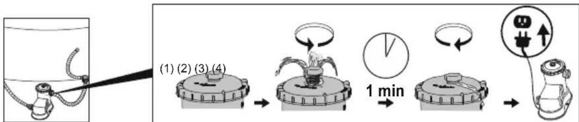
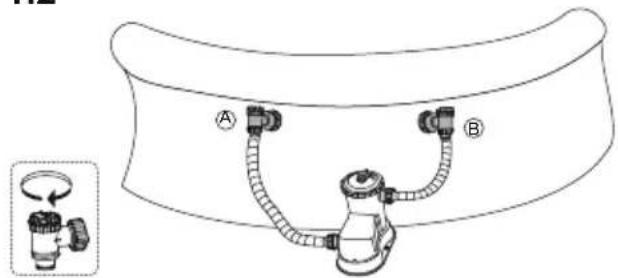
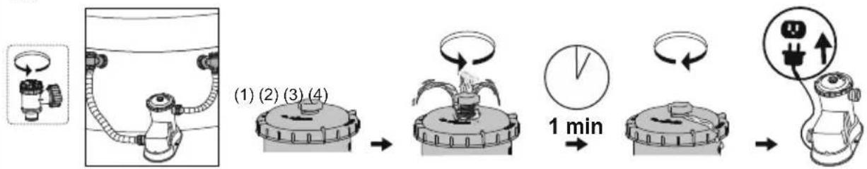
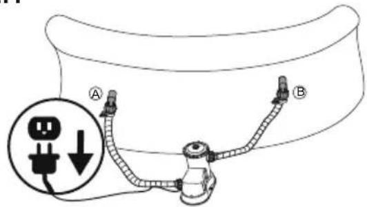
- It is imperative to check that the hydraulic connectors are not obstructed.
- Do not dry run the Filter Pump. Make sure both the pool's inlet and outlet valves are fully covered by water before operating the Filter Pump.
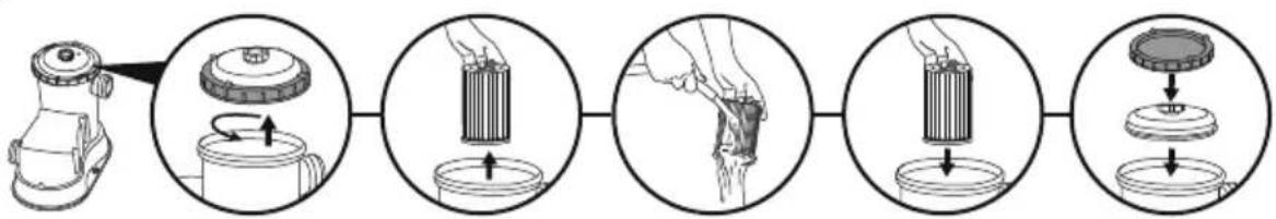
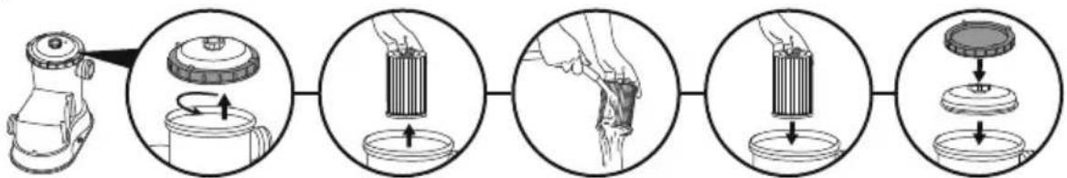
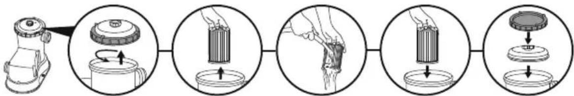
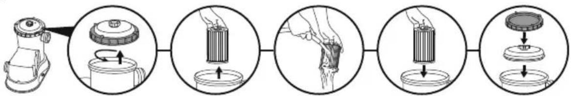
MAINTENANCE
- Make sure that the Filter Pump is unplugged before any maintenance.
- For the maintenance instructions, refer to illustration steps inside the manual. Drawings are for illustration purposes only. May not reflect actual product. Not to scale.
- To optimize the Filter Pump performance and for sanitary reasons, we suggest replacing the filter cartridge with a new one every two weeks.
STORAGE
- Remove all accessories; be sure that Filter Pump, hoses and debris screens are completely clean and dry before the storage. If all the parts are not completely dry, mold may result.
- Before storage, remove and dispose of the filter cartridge.
- We strongly recommend disassembling the Filter Pump when the environment temperature is below 50^ / 10^ .
- Store the Filter Pump in a dry place with a moderate temperature between 50^ / 10^ and 100^ / 38^ .
WARRANTY TERMS
For information concerning warranty terms, visit our website at: www.bestwaycorp.com.

CONDITIONS DE GARANTIE
CONDITIONS DE GARANTIE
text_image
Exploded view diagram of a blender with numbered parts for identification| V1 | V2 | V3 | V4 | |
| 1 | x1 | x1 | x1 | x1 |
| 2 | x1 | x1 | x1 | x1 |
| 3 | x1 | x1 | x1 | x1 |
| 4 | x1 | x1 | x1 | x1 |
| 5 | x1 | x1 | x1 | x1 |
| 6 | x2 | x2 | x3 | x3 |
| 7 | x2 | x2 | x2 | x2 |
| 8 | x0 | x0 | x2 | x2 |
| 9 | x0 | x2 | x0 | x2 |
| 10 | x0 | x2 | x4 | x5 |
| 11 | x0 | x0 | x1 | x1 |
| 12 | x0 | x0 | x2 | x2 |
| 13 | x0 | x0 | x2 | x2 |
| 14 | x0 | x1 | x0 | x1 |
| 15 | x0 | x1 | x0 | x0 |
text_image
Diagram showing exploded view of a mechanical component with numbered parts, likely for assembly or labeling.V1 x2
V2 x2
V3 x1 x2
V4 x3
natural_image
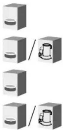
Four grayscale 3D boxes with circular patterns, each containing a small object inside (no text or symbols)

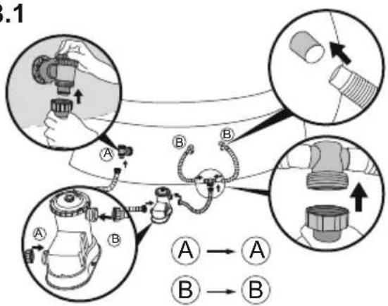
1.1
text_image
A B1.2
text_image
A B A B1.3
natural_image
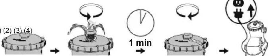
Simple line drawing of a mechanical component with no text or symbols(1) (2) (3) (4)
flowchart
graph LR
    A["(2) (3) (4)"] --> B["Motor with rotating arm"]
    B --> C["1 min"]
    C --> D["Clock with rotation arrow"]
    D --> E["Electrical connection with power plug"]
    E --> F["End"]


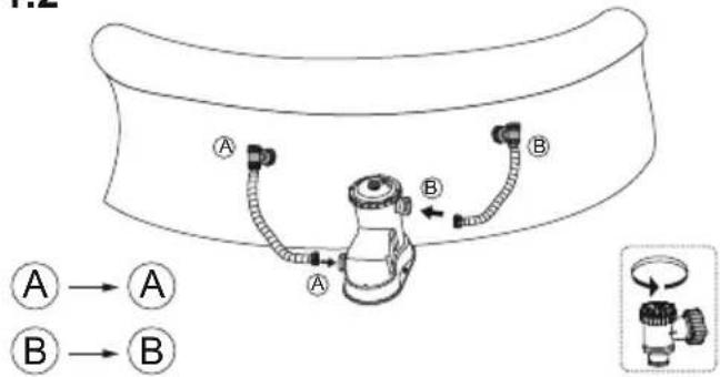
2.1 2.2
text_image
Diagram illustrating mechanical assembly steps with labeled components A and B, showing directional movement and component placement.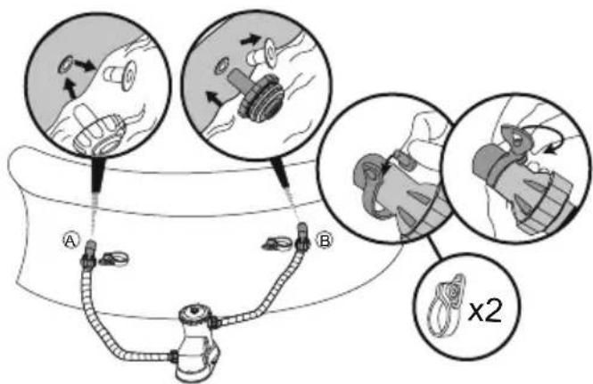
text_image
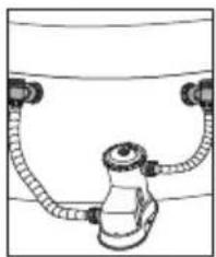
Diagram illustrating a medical or surgical procedure with labeled components A and B, showing mechanical assembly and cross-sectional views.2.3
natural_image
Simple line drawing of a mechanical component with two curved arms and a central hub (no text or symbols)(1) (2) (3) (4)
flowchart
graph LR
    A["(2) (3) (4)"] --> B["1 min"]
    B --> C["Step 1: Rotation of rotating component"]
    C --> D["Step 2: Rotation of electrical plug"]
    D --> E["End"]


3.1
flowchart
graph TD
    A["Car with valve"] --> B["Switch"]
    B --> C["Gear shift"]
    C --> D["Assembly"]
    D --> E["Car with gear"]
    style A fill:#f9f,stroke:#333
    style B fill:#ccf,stroke:#333
    style C fill:#cfc,stroke:#333
    style D fill:#fcc,stroke:#333
3.2
text_image
A B B x43.3
flowchart
graph LR
    A["Water jar with inlet"] --> B["(1) (2) (3) (4)"]
    B --> C["1 min"]
    C --> D["1 min"]
    D --> E["1 min"]
    E --> F["1 min"]


4.1 4.2
flowchart
graph TD
    A["Valve with Bag"] --> B["Car with Pipe"]
    B --> C["Wheel with Rope"]
    C --> D["Gear with Bulge"]
    D --> E["Arrow to Valve A"]
    D --> F["Arrow to Gear B"]
    style A fill:#f9f,stroke:#333
    style B fill:#ccf,stroke:#333
    style C fill:#cfc,stroke:#333
    style D fill:#fcc,stroke:#333
    style E fill:#ffc,stroke:#333
    style F fill:#cff,stroke:#333
text_image
A B B x54.3
flowchart
graph LR
    A["Water tank with tubing"] --> B["(1) (2) (3) (4)"]
    B --> C["Reactor with flame"]
    C --> D["1 min"]
    D --> E["Reactor with circuit"]
    E --> F["Electricity meter connected to condenser"]


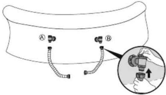
1.1
text_image
Diagram showing a pipe connection with labeled points A and B, including a magnified inset indicating a plug symbol.1.2
text_image
Diagram of a medical or laboratory device with labeled parts A and B, showing tubing connections and a magnified inset view.1.3
flowchart
graph LR
    A["Raw Material"] --> B["Rolling"]
    B --> C["Packing"]
    C --> D["Drinking"]
    D --> E["Product"]
1.4
flowchart
graph LR
    A["Initial Setup"] --> B["(1) (2) (3) (4)"]
    B --> C["Step 1: Water Spray"]
    C --> D["Step 2: Round-over Rose"]
    D --> E["Step 3: Roundover Rose"]
    E --> F["Step 4: Roundover Rose"]
    F --> G["Final Discharge"]


2.1
text_image
Diagram of a cable or connector assembly with labeled parts A and B, showing wiring connections and a magnified inset showing a plug symbol.2.2
text_image
Diagram illustrating a medical procedure with labeled steps A and B, showing mechanical components and a magnified view of the procedure.2.3
flowchart
graph LR
    A["Lathe with lid"] --> B["Rotation: 100%"]
    B --> C["Boiling: 50%"]
    C --> D["Cutting: 20%"]
    D --> E["Stacked lid: 50%"]
    E --> F["Final product: 50%"]
2.4
flowchart
graph LR
    A["Initial Device"] --> B["Step (1) (2) (3) (4)"]
    B --> C["Step (1) (2) (3) (4) in a circular component"]
    C --> D["Step (1) (2) (3) (4) in a circular component with a valve, 1 min mark"]
    D --> E["Step (1) (2) (3) (4) in a circular component with a plug, 1 min mark"]


3.1

text_image
Diagram showing a plug plug connected to a cable with labeled points A and B, and a magnified view of the plug plug symbol.3.2
text_image
3.2 A B x43.3
flowchart
graph LR
    A["Bottle with lid"] --> B["Coating with lid"]
    B --> C["Cut into container with lid"]
    C --> D["Close-up of lid with lid"]
    D --> E["Close-up of lid with lid"]
    E --> F["Close-up of lid with lid"]
3.4
flowchart
graph LR
    A["Patient with laparoscopic implant"] --> B["Step (1) (2) (3)"]
    B --> C["Step (1) (2) (3) in a device"]
    C --> D["Step (1) (2) (3) in a device with clockwise motion"]
    D --> E["Step (1) (2) (3) in a device with clockwise motion"]
    E --> F["Step (4) (4) in a device with electrical plug and power source"]


4.1
text_image
Diagram showing a plug connected to a hose with labeled points A and B, accompanied by an electrical outlet symbol.4.2
text_image
A B B x54.3
flowchart
graph LR
    A["Shuttered lathe"] --> B["Coating lid"]
    B --> C["Coating cylinder with arrow indicating rotation"]
    C --> D["Coating drop into container with liquid"]
    D --> E["Coating lid with arrow indicating cooling step"]
4.4
text_image
Diagram illustrating fluid flow and mechanical components with labeled parts A and B, showing fluid movement and movement directions.(1) (2) (3)


1 min

(4)
text_image
Diagram showing a plug with lightning bolt and upward arrow, connected to a battery pack with plug symbolBestway®
For support please visit us at:
bestwaycorp.com/support
©2022 Bestway Inflatables & Material Corp.
All rights reserved/Tous droits réservés/Todos los derechos reservados/Alle Rechte vorbehalten/Tutti i diritti riservati
Trademarks used in some countries under license from/
Manufactured, distributed and represented in the European Union by/
Distributed in Australia & New Zealand by Bestway Australia Pty Ltd, Unit 2/98-104 Carnarvon St Silverwater, NSW 2128, Australia
Tel: Australia: (+61) 2 9037 1388; New Zealand: 0800 142 101
Distributed in United Kingdom by Bestway Corp UK Ltd. 8 Wentworth Road, Heathfield Industrial Estate, Newton Abbot, Devon, TQ12 6TL
Exported by/Exporté par/Exportado por/Exportiert von/Esportato da
Bestway (Hong Kong) International Ltd./Bestway Enterprise Company Limited
Suite 713, 7/Floor, East Wing, Tsim Sha Tsui Centre, 66 Mody Road, Kowloon, Hong Kong
www.bestwaycorp.com