Door eGuard DG 8100 - Security and Access Control System Burg Wächter - Free user manual and instructions
Find the device manual for free Door eGuard DG 8100 Burg Wächter in PDF.
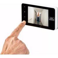
| Product type | Digital peephole with camera and color screen |
| Brand | Burg Wächter |
| Model | Door eGuard DG 8100 |
| Dimensions (W x H x D) | 139 x 77 x 15.8 mm |
| Weight | 185 g |
| Power supply | 4 AAA 1.5 V alkaline batteries |
| Compatible door thickness | 38 to 110 mm |
| Door hole diameter | 14 to 26 mm |
| Camera resolution | 0.3 Megapixels |
| Screen | 4.0" TFT LCD, QVGA resolution (480 x 320) |
| Internal storage | Approximately 50 photos |
| External storage | micro SD card up to 8 GB (Class 6 HDSC recommended) |
| Main functions | External observation, photo taking, image browsing and deletion, automatic display when doorbell rings |
| System settings | Time, date, ringtone, volume (0-3), auto power off, backup media selection |
| Accepted battery type | AAA 1.5 V alkaline |
| Maintenance and cleaning | Wipe with a dry cloth; do not use alcohol, benzene solvent, or chemicals |
| Safety | Do not repair or modify yourself; comply with data protection regulations for video surveillance |
| General information | Easy wireless installation; replaces traditional optical peephole; wide viewing angle |
Frequently Asked Questions - Door eGuard DG 8100 Burg Wächter
User questions about Door eGuard DG 8100 Burg Wächter
0 question about this device. Answer the ones you know or ask your own.
Ask a new question about this device
Download the instructions for your Security and Access Control System in PDF format for free! Find your manual Door eGuard DG 8100 - Burg Wächter and take your electronic device back in hand. On this page are published all the documents necessary for the use of your device. Door eGuard DG 8100 by Burg Wächter.
USER MANUAL Door eGuard DG 8100 Burg Wächter
text_image
Diagram of a medical device with labeled components including battery, switch, and earpiece parts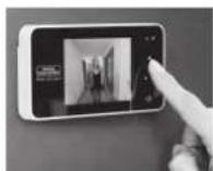
Abbildung
A Digitaler Türspion
B Charge indicator lamp
c 1 attachment screw
D 4 x AAA batteries
E Holding plate
F Camera
G Fastening sleeve
H Tightening tool
Figure
natural_image
Diagram showing three types of medical or mechanical devices: a syringe inserted into a plate, a circular device with a handle, and a separate view of a bulb (no text or symbols present)(Abb. 1)

text_image
Diagram illustrating three different switch mechanism steps with labeled components and directional arrows(Abb. 2)

natural_image
Simple line drawing of a person inside a rectangular frame with control buttons (no text or symbols)(Abb. 3)(Abb. 4)
text_image
Diagram of a device panel with numbered labels pointing to icons for display, navigation, and control buttons.text_image
18 10s 15s 20s 5 6natural_image
Simple grayscale image of a cylindrical container with a leaf icon, placed on a plain surface with directional arrows and a checkmark (no text or symbols)text_image
Warning symbol image with exclamation mark inside a triangle- All rights reserved including any changes of product appearance, technical function and usage without prior notice to users.
- Use of this product other than that for which it is intended for or any modification to the original specification will invalidate any guarantee given.
- Use of this product in any environment or in any way other than specified here will also invalidate the guarantee.
Attention
- Please read this user manual carefully before using our product.
- Never attempt to repair or modify this product or its accessories by yourself, to avoid injury and invalidating guarantee!
- Any accidental factor such as being struck by lightning or any incorrect operation could cause a memory loss on the micro sd-card.
Keeping copies of the pictures is strongly recommended in case of memory loss. We are not responsible for any loss of data. - DO NOT use any chemicals to clean this product, such as alcohol or benzene thinner.
- Please change the batteries soon after the low-battery indicator shows, in order to avoid any damage to this product which could be caused by battery weeping.
Dear customer,
thank you very much for deciding for Door eGuard manufactured by BURG-WÄCHTER. Door eGuard is a battery-operated system with a camera and colour monitor, easy to install and providing its user with the certainty of being able to see anything happening outside the entrance door without being seen. Thanks to its large adjustment range, this door spyhole can be used with any common door with a thickness from 38 to 110 mm. The camera optics can cover existing holes in the door of 14 – 26 mm. Thanks to the camera optics with a large viewing angle, even persons hidden near the door can be identified.
Important: Please read the entire User Manual before you start to mount the device.
Let us wish you a high level of security and quality of living with your electronic spyhole. Your BURG-WÄCHTER KG
Installation instructions
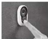
-
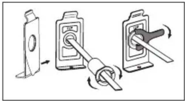
Replace the existing door viewer or drill a 14mm hole in the door at the required height. Peel off the 3M sticker top layer and then insert the camera from the outside. Ensure the door bell button is under the camera and adjust the camera vertically to the ground (FIG.1)
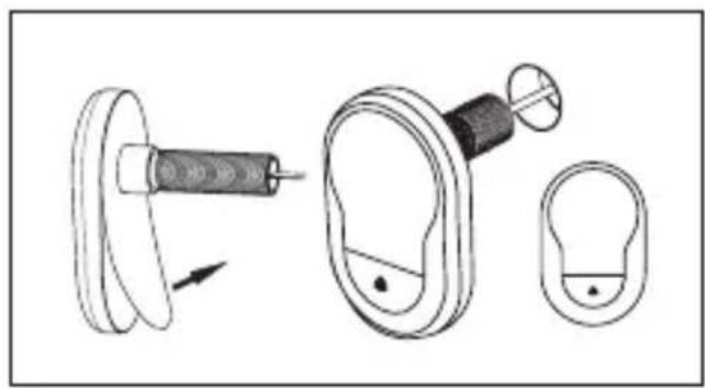
-
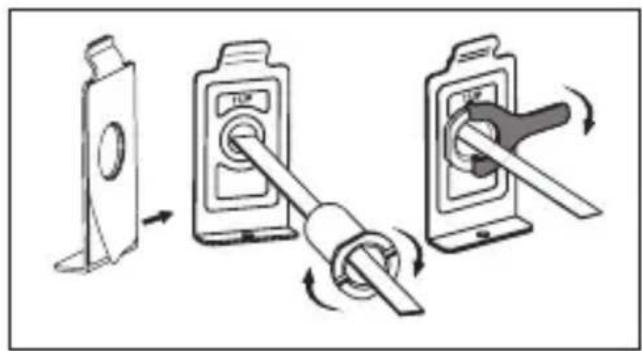
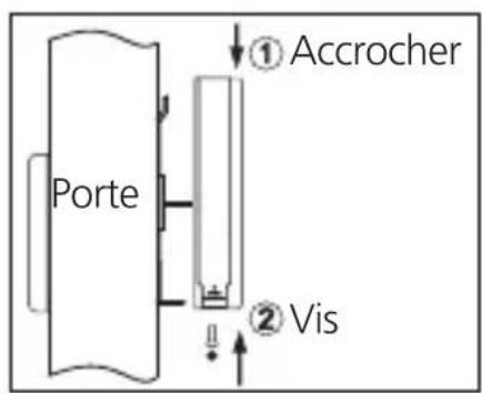
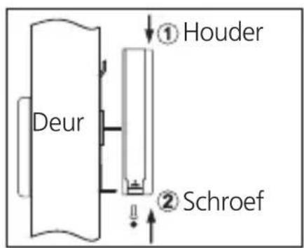
Peel off the 3M sticker top layer on the holding plate and fit the holding plate over the end of the camera wires on to the back of the door. Make sure the arrow on the holding plate points upwards. Then screw up the locking barrel on to the back of the camera. This will hold the plate to the door (FIG.2)
-
When inserting the camera wire into the socket, ensure you match the connectors correctly.(If inserted the wrong way, this can damage the wires on the camera) The excessive wire should be gently placed into the groove at the back of the screen.
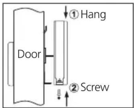
- Hook the screen over the bracket at the top of the holding plate and secure with one small screw through the hole at the bottom of the screen case. (FIG.3)
natural_image
Diagram showing a mechanical assembly with a spring-loaded component and two separate views of a circular component (no text or symbols)(FIG. 1)
text_image
Diagram showing three-step switch mechanism with labeled components and directional arrows(FIG. 2)
text_image
① Hang Door ② Screw
natural_image
Simple line drawing of a person inside a rectangular frame with dots at the bottom (no text or symbols)(FIG. 3)(FIG. 4)
Installation and replacement of batteries
Installation:
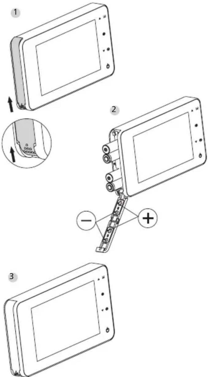
1 Slide the lid upwards to open, as shown in diagram.
2 Put in the batteries according to the "+" "-" sign on the lid.
3 Take the reverse steps to close the lid.
Vorsicht:
- DO NOT force when opening and closing the lid to avoid lid damage.
- DO NOT press the lid to the opposite direction when opening to avoid any lid damage.
- When the low battery indicator is on, please replace all batteries to avoid any damage to this product by battery weeping.
When the batteries run out, the low battery indicator will flash to remind users to replace the batteries. The following types of batteries can be used in this product: AAA, 1.5 V alkaline battery. Any abandoned batteries should be disposed according to local environment protection rules and regulations.
Operation instruction
Parts specifications
text_image
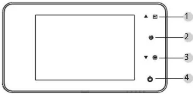
Diagram of a device control panel with labeled buttons and icons for display, zoom, and navigation functions.Button functions:
| No | basic function | multi functions |
| 1 | Up · In home page, press UP button to enter picture browse mode; · After enters picture browse mode, press UP button to browse pictures backwards; · In setting mode, press Up button to adjust the item you selected; | |
| 2 | Down · In picture | browse mode, press Down button to browse pictures onwards; · In setting mode, press Down button to adjust the item you selected; · In home page, press Down button to take picture. |
| 3 | Menu · Press Menu button to enter menu page; · When deleting pictures, press Menu button you can then choose to delete the current photo; · In picture browse and setting mode, press and hold the menu button to exit the current page. |
| 4 | Power Button · After installing new batteries, press and hold power button to start. |
Back side of screen case
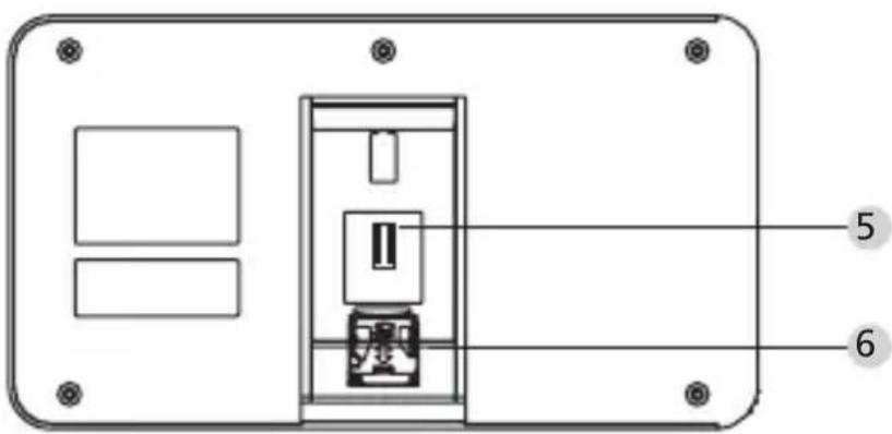
text_image
Technical diagram of a device rear panel with labeled components and mounting holes5 camera data wire connector
6 micro sd-card socket
System settings
- Under normal mode, press '☐' to enter setting mode.
- Then you should see the below setting mode page.
- Press "☐" to find different settings:
Time--Date--Ringtone--Volume--Auto power-off time--Save file in - Press "▼" to change the settings.
- In TIME / DATE setting, press "▼" will increase the current number; Holding the button down will accelerate the adjustment.
- After the setting is changed, the system will automatically save the result and exit the setting page in a few seconds.
- If you need to exit the setting page, press and hold "☐☐".
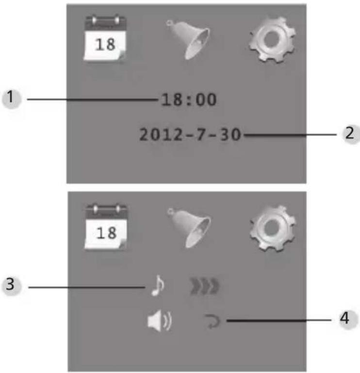
text_image
1 18:00 2012-7-30 18 18 4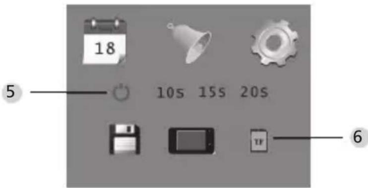
text_image
18 5 10s 15s 20s 61 Time setting
2 Date setting
3 Ringtone setting
4 Volume setting 0: silent mode
3: Max volume
5 Auto power-off setting
6 Save file in
- local file (data can not be downloaded)
- micro sd-card (data can be loaded from the sd-card via card reader)
To observe outdoors
- Under normal mode, you can observe outdoors once you press the power button.
- When visitors press the door bell, the bell will ring inside the room.
The screen will automatically turn on showing the image of outside. It will automatically power off once the set time is reached. - Under normal mode, press “▼” will take a picture of outdoors and save it automatically.
Visitors
- When visitors press the door bell button on the door viewer camera, the door bell will ring inside the room.
- Meantime, the screen will automatically turn on, showing the image of outdoors. It will automatically power off once it reaches the set time.
- Also as the door bell is pressed, the camera will automatically take a photo of the visitors and the photo will be stored in the set file in case the host is out, so as to check the visitors' identity afterwards or to use the information for security purposes.
Replay and delete of the photos
- Under normal mode, press "▲" to replay photos.
- When you browse the photos, press "▲" or "▼" to choose photos.
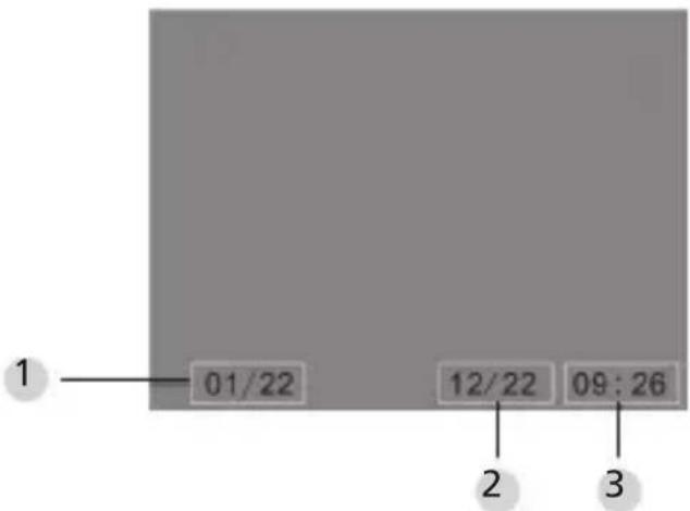
text_image
1 01/22 12/22 09:26 2 31 Current photo number / total number
2 Month/date
3 Shooting time
When you check the photos, press button "qq" to choose to delete the current photo.
After a short press on the button, you will see below icon:
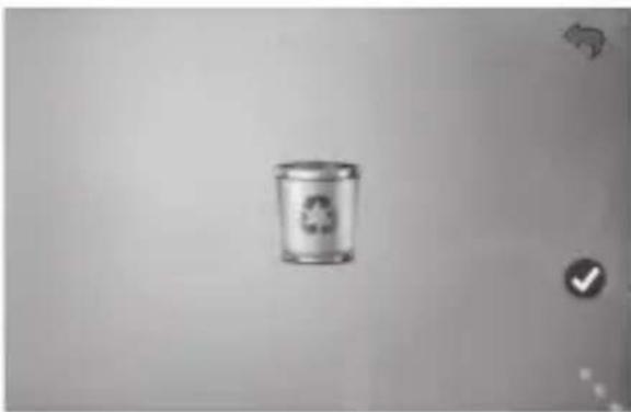
natural_image
Simple grayscale image of a recycling bin with a recycling symbol, no text or labels present.- Press" "to confirm to delete.
Choose your auto-store file
- Users can choose to save photos in local file or TF card.
- The default store is local file.
Memory Card Installation
- There is NO micro sd-card included. This should be purchased by user separately.
- Please insert the micro sd-card before installing batteries.
- Before inserting the micro sd-card, make sure the metal cover above the micro sd-card socket is pushed towards the OPEN mark.
- Lift and open the upper of the metal cover and insert micro sd-card into the metal cover.
- Then replace the metal cover and push back to LOCK mark.
- Max. 8 GB micro sd-card can be used, over HDSC Class 6 is suggested.
Specifications
| Door thickness 38~110mm | |
| Camera 0.3 Mega pixels | |
| LCD Screen 4.0" TFT | |
| Resolution QVGA (480x320) | |
| Power 4 AAA, | 1.5 V alkaline battery |
| Local memory storage | Approx 50 photos (The amount could differ depending on the type of environment the camera is situated in) |
| Exterior card type | Micro SD-card (TF), max 8 GB |
| Photo volume for 1 | 2,000 pc (lab condition, the actual volume could differ under different circumstances) |
| Size 139(w)x77(H)x15.8(D)mm | |
| Weight 185g | |
Caution
Alterations and modifications that are not explicitly authorised by the responsible approval agency, can lead to a deprivation of the permission to use the device.
Important: Legal note

text_image
Warning symbol image with exclamation mark inside a triangleAcquisition, recording and saving of video surveillance data (sound and vision) are regulated by strict German guidelines. Please note the valid provisions regarding data protection laws that are stipulated in the Federal Data Protection Act resp. Land Protection Act. For other countries the respective national data protection laws are valid.
Disposal
Dear customer,
Please help us avoid unnecessary waste. Should you ever intend to dispose of this device, please bear in mind that many components of the device contain precious materials, which can be recycled.
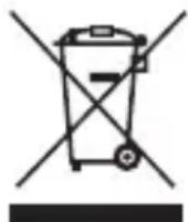
Please be aware that electrical and electronic equipment and batteries shall not be disposed of as household waste, but rather collected separately. Please obtain information on the collecting points for electrical waste from the responsible authority of you municipality.

If you have any questions concerning the EC declaration of conformity, please use info@burg.biz.
Mistakes and changes reserved.
JUDAS ÉLECTRONIQUE NOTICE D'UTILISATION
text_image
Diagram showing a medical or surgical procedure with labeled components and directional arrows indicating movement.(Fig. 1)
text_image
Diagram showing three different switch mechanism steps with labeled components and directional arrows indicating rotation or adjustment.(Fig. 2)
text_image
Accrocher Porte ① ② Vis
natural_image
Simple line drawing of a person inside a rectangular frame with control buttons (no text or symbols)(Fig. 3)(Fig. 4)
text_image
18 5 10s 15s 20s 6natural_image
Simple illustration of a bin with a recycling symbol, no text or labels presenttext_image
Warning symbol image with exclamation mark inside a trianglenatural_image
Diagram showing a medical or surgical tool interacting with a device, including a magnified view of the ear and a separate inset (no text or symbols present)(AFB. 1)

text_image
Diagram illustrating three-step switch mechanism with labeled components and directional arrows(AFB.2)
text_image
Deur ① Houder ② Schroef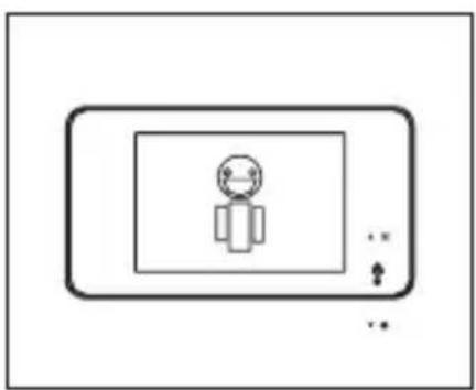
natural_image
Simple line drawing of a person inside a rectangular frame with control buttons (no text or symbols)(AFB.3)(AFB.4)