CFBG901OWBE - Cooker BORETTI - Free user manual and instructions
Find the device manual for free CFBG901OWBE BORETTI in PDF.
| Product Type | Cooker |
| Brand | Boretti |
| Model | CFBG901OWBE |
| Power Supply | Gas (G20/G25, G30/G31) and electric 220-240 V |
| Hob | 5 gas burners: 1 auxiliary (1.0 kW), 1 semi-rapid (1.75 kW), 1 rapid (3.0 kW), 1 double (4.0 kW) |
| Oven | Electric multifunction with 8 functions, thermostat 50-250°C, electronic programmer |
| Electrical Power | 220-240 V, cable section 3 x 1.5 mm² |
| Weight | Approximately 70 kg (estimate) |
| Dimensions (W x D x H) | Approximately 90 x 60 x 85 cm (estimate) |
| Oven Functions | Conventional cooking, bottom heat, top heat, grill, fan grill, forced convection, hot air, defrosting |
| Safety | Safety device on all burners (automatic shut-off in case of extinction), anti-tilt bracket |
| Cleaning | Enamelled and stainless steel surfaces: wash with sponge and neutral soap; removable inner glass for cleaning |
| Spare Parts | Replacement injectors, halogen bulbs (220-240 V, 300°C), gaskets, burners |
| Repairability | Intervention by qualified technician recommended for gas and electricity; bulb replacement by user |
| General Information | Domestic use only, warranty void if used commercially; do not use as heating |
Frequently Asked Questions - CFBG901OWBE BORETTI
User questions about CFBG901OWBE BORETTI
0 question about this device. Answer the ones you know or ask your own.
Ask a new question about this device
Download the instructions for your Cooker in PDF format for free! Find your manual CFBG901OWBE - BORETTI and take your electronic device back in hand. On this page are published all the documents necessary for the use of your device. CFBG901OWBE by BORETTI.
USER MANUAL CFBG901OWBE BORETTI
natural_image
Exterior view of a stainless steel electric stove with four gas stove top and open door (no visible text or symbols)
CFBG901AN / CFBG901ANBE / CFBG901IX / CFBG901IXBE / CFBG901OW / CFBG901OWBE / CFBG901ZW / CFBG901ZWBE
GB | INSTRUCTIONS ON MOUNTING AND USE NL | MONTAGEVOORSCHRIFTEN EN GEBRUIKSAANWIJZING F | PRESCRIPTIONS DE MONTAGE ET MODE D'EMPLOI D | MONTAGE- UND GEBRAUCHSANWEISUNG
Nederlands
Instruction for the use - Installation advice
Page 181
Descriptions and illustrations in this booklet are given as simply indicative.
The manufacturer reserves the right, considering the characteristics of the models described here, at any time and without notice, to make eventual necessary modifications for their construction or for commercial needs.
natural_image
Symbol of a trash bin crossed with no visible text or labelsBELANGRIJKE VEILIGHEIDSINSTRUCTIES EN AANBEVELINGEN
text_image
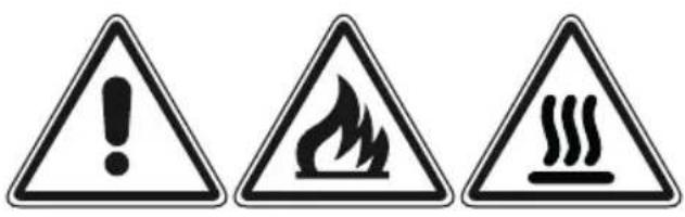
Warning sign set with three triangular warning symbols: exclamation mark, flame symbol, and steam train icon
text_image
Diagram showing a kitchen with a crossed-out cloth and steam rising, indicating a warning or hazard.OPGELET – HEEL BELANGRIJK !
BRAND/OVERVERHITTINGSGEVAAR:
natural_image
Diagram of a curved mechanical component with directional arrows indicating motion, labeled 'Afb. 3.2' (no text or symbols on the diagram itself)Voorzichtig!
natural_image
Symmetrical abstract diagram with concentric circles and small circular elements, no text or symbols present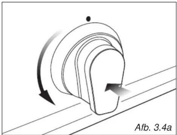
natural_image
Diagram of a curved mechanical component with directional arrows indicating motion, labeled 'Afb. 3.4a' (no text or symbols on the diagram itself)
natural_image
Diagram of a mechanical component with curved arrows indicating motion, labeled 'Afb. 3.4b' (no text or symbols on the diagram itself)natural_image
Two simple line drawings of a cooking pot and a gas stove with flames, labeled 'Afb. 3.5' (no text or symbols on the devices themselves)text_image
Diagram illustrating three-step assembly process: top-down, cross-section, and final step with checkmark
text_image
S T Afb. 6.3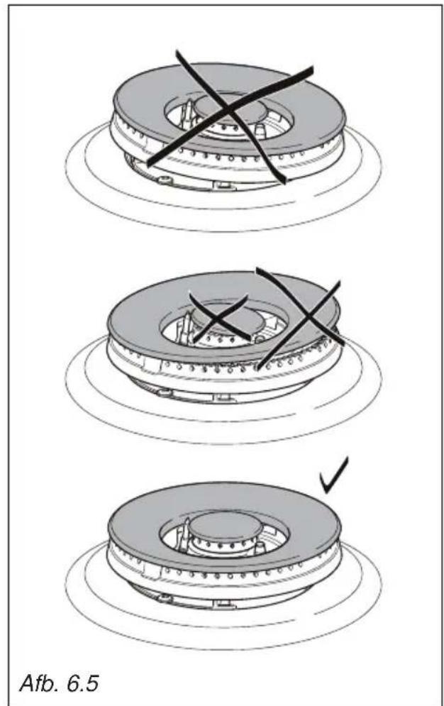
text_image
Afb. 6.5
text_image
Afb. 6.4MONTEREN EN DEMONTEREN VAN DE ZIJPLATEN
natural_image
Technical line drawing of a mechanical component with a hand inserting a tool into a housing (no text or symbols)DRAGERS TELESCOPISCHE VERSCHUIFBARE LEGGERS (afb. 6.8)
natural_image
Technical line drawing of a heat exchanger or cooling unit with no visible text or symbolsnatural_image
Technical line drawing of a mechanical component with two parallel plates and directional arrows indicating assembly or movement (no text or symbols)
natural_image
Technical diagram showing mechanical components with magnified views of detail (no text or symbols)
natural_image
Technical line drawing of a rectangular grid structure with internal partitions (no text or symbols)Afb. 6.13Afb. 6.12
text_image
13Afb. 6.12 2 2 1VERVANGEN VAN HET OVENLAMPJE
text_image
WROONG CORRECT
text_image
A B A Afb. 6.14SCHOTELWARMHOUDRUIMTE
natural_image
Technical line drawing of a mechanical assembly with mounting feet and a transparent panel (no text or symbols)VERWIJDEREN EN VERVANGING VAN DE RUITEN IN DE BINNENDEUREN VOOR REINIGING
natural_image
Technical line drawing of a mechanical bracket assembly (no text or symbols)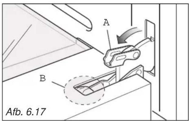
text_image
A Afb. 6.17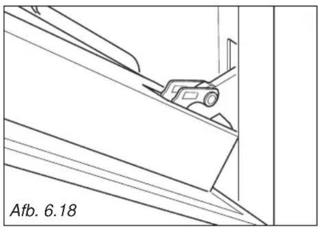
natural_image
Technical line drawing of a mechanical component or bracket with diagonal lines and a small object, labeled 'Afb. 6.18' at bottom (no other text or symbols)
natural_image
Line drawing of a person installing or adjusting a door panel, no text or symbols presenttext_image
Warning symbol illustration showing a warning triangle with an exclamation mark and a hand holding a glove crossed out.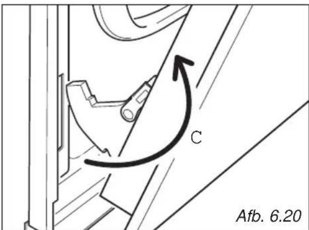
text_image
C Afb. 6.20text_image
2 Click M 1 M 1 M 2 Click Afb. 6.24HERMONTEREN VAN DE OVENDEUR
natural_image
Line drawing of two hands holding a wooden plank, labeled 'Afb. 6.25' (no other text or symbols)
natural_image
Technical diagram showing a mechanical component with an arrow indicating motion, labeled 'Afb. 6.26' (no readable text or symbols beyond label)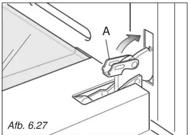
text_image
A Afb. 6.27natural_image
Technical line drawing of a structural support frame with mounting holes and supports (no text or symbols)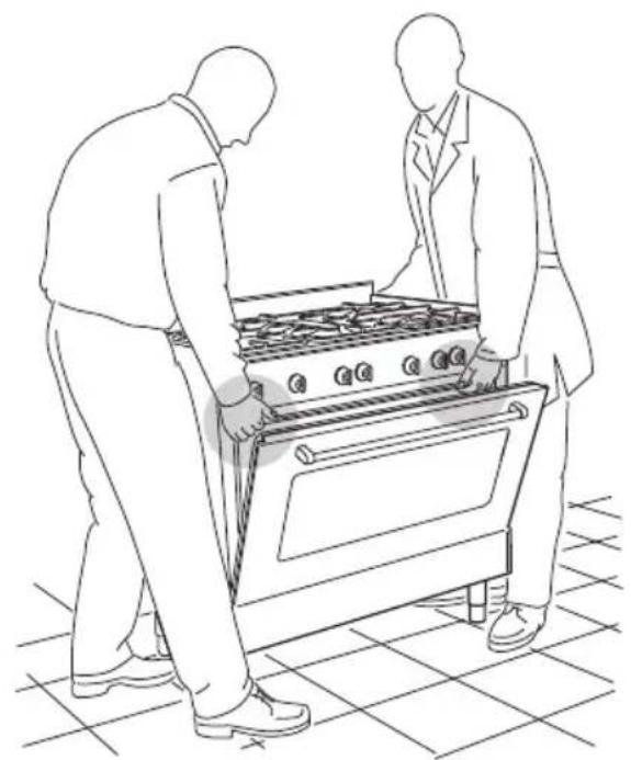
natural_image
Line drawing of two people assembling a large stove on a tiled floor (no text or symbols)Afb. 7.4
BEWEGINGSSYSTEEM VAN HET FORNUIS
WAARSCHUWING
natural_image
Line drawing of a person using a stove with crossed lines indicating resistance or work (no text or symbols)WAARSCHUWING
natural_image
Technical diagram showing a mechanical component with rotational arrows and directional arrows, labeled 'Afb. 7.7' (no text or symbols on the diagram itself)BEVESTIGINGSSTEUN
natural_image
Technical line drawing of a cabinet with mounting feet and a door, showing no text or symbols on the main structure.EISEN VOOR DE VENTILATIE
natural_image
Line drawing of hands using a wrench to lift a pipe, labeled 'Afb. 8.2a' (no other text or symbols)
natural_image
Illustration of hands using a wrench to tie a rope or cable (no text or symbols present)
Cat: II 2EK3B/P
natural_image
Illustration of hands using a wrench to tie a vertical pipe (no text or symbols present)Metalen R_HT slang AGB/BGV erkend
text_image
Technical diagram showing a hand operating a tool to lift a mechanical component, labeled with 'J' and a tool handle.Afb. 8.9
natural_image
Symbol of a trash bin crossed with two diagonal lines (no text or numbers present)
ENERGIEVERBRAUCHSKENNZEICHNUNG/ÖKODESIGN
text_image
Warning sign with three triangular warning symbols: exclamation mark, flame symbol, and steam train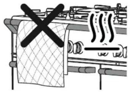
text_image
Diagram showing a kitchen with a crossed-out shower and smoke, indicating a warning or hazard.natural_image
Diagram of a curved mechanical component with directional arrows indicating motion, labeled Abb. 3.2 (no text or symbols on the diagram itself)natural_image
Symmetrical abstract diagram with concentric circles and decorative elements, no readable text or symbols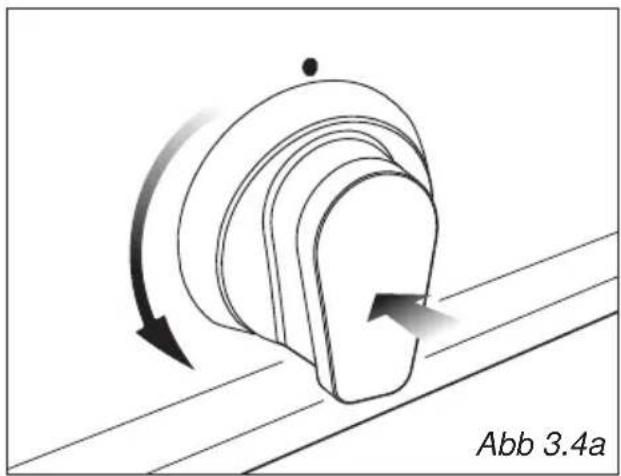
natural_image
Diagram of a curved mechanical component with directional arrows indicating motion, labeled Abb 3.4a (no text or symbols on the diagram itself)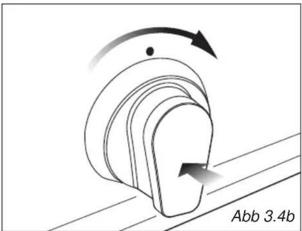
natural_image
Diagram of a mechanical component with curved arrows indicating motion, labeled Abb 3.4b (no text or symbols on the diagram itself)text_image
Diagram illustrating three-step assembly process of a mechanical component, showing disassembly and reassembly with cross marks.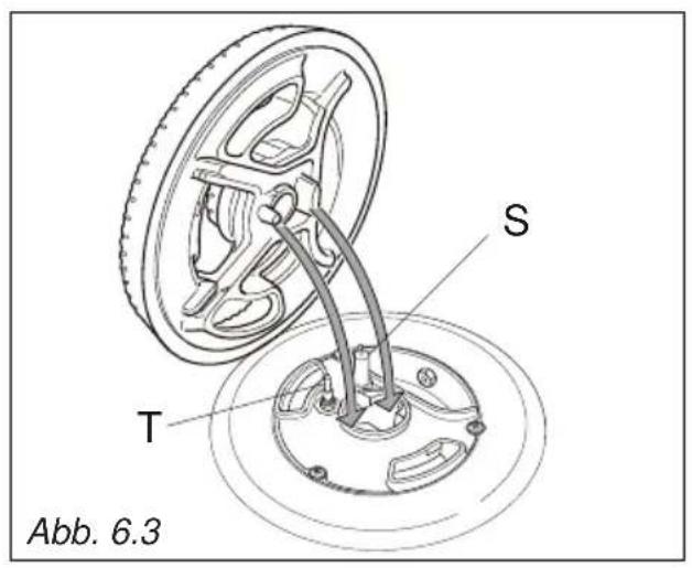
text_image
S T Abb. 6.3
text_image
Abb. 6.5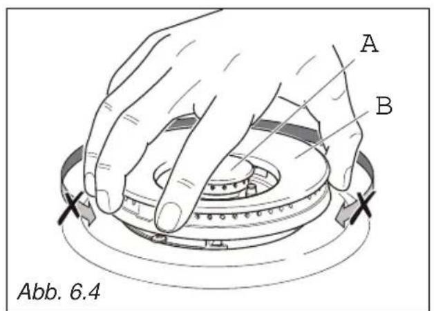
text_image
A B Abb. 6.4EINSETZEN DER BACKOFENROSTE
natural_image
Technical line drawing of a mechanical component with a hand adjusting a central circular feature (no text or symbols)natural_image
Technical line drawing of a heat exchanger or cooling unit with cooling fins and cooling ends (no text or symbols)
text_image
Abb. 6.11 Abb. 6.10 Leitschiene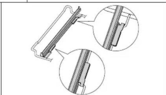
natural_image
Technical line drawing of a mechanical component with three circular inset views showing internal features (no text or symbols)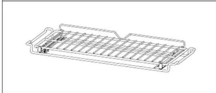
natural_image
Technical line drawing of a rectangular metal frame structure with internal grid lines (no text or symbols)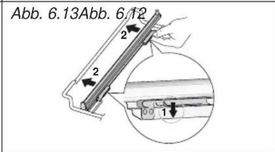
text_image
Abb. 6.13Abb. 6.12 2 2 1natural_image
Technical line drawing of a mechanical assembly with mounting feet and a transparent panel (no text or symbols)natural_image
Technical line drawing of a mechanical bracket assembly (no text or symbols)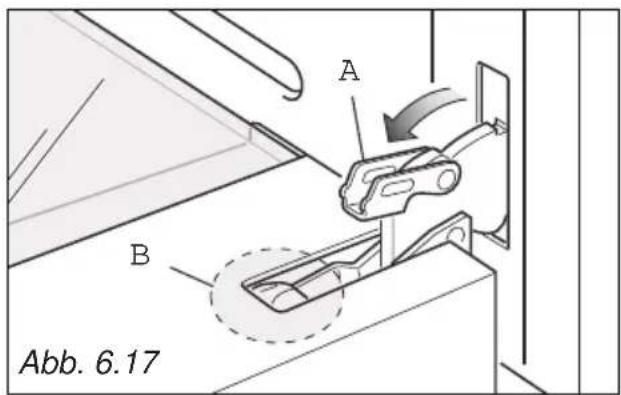
text_image
A B Abb. 6.17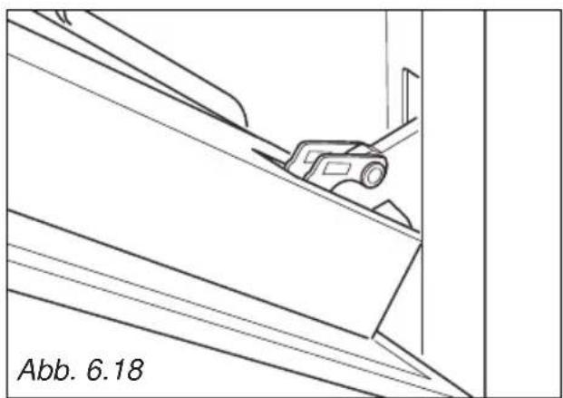
natural_image
Technical line drawing of a mechanical component with diagonal lines and a labeled section (no text or symbols on the diagram itself)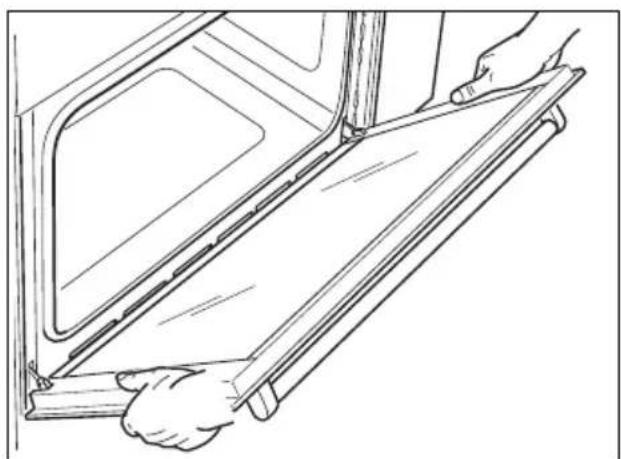
natural_image
Line drawing of a person installing or adjusting a door panel inside a vehicle (no text or symbols)OFENTÜR ABMONTIEREN
text_image
Warning symbol illustration showing a warning triangle with an exclamation mark and a hand holding a bag, alongside a crossed-out hand.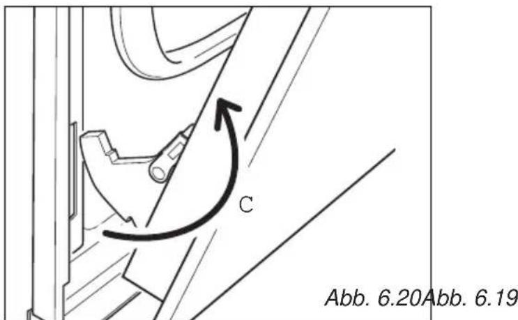
text_image
C Abb. 6.20Abb. 6.19natural_image
Line drawing of two hands holding a wooden ruler or scale, labeled 'Abb. 6.25' (no other text or symbols)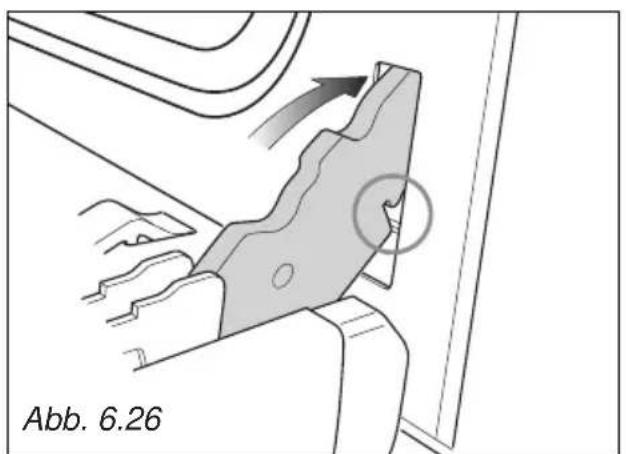
natural_image
Technical diagram showing a mechanical component with directional arrows and a circled feature, labeled Abb. 6.26 (no readable text or symbols)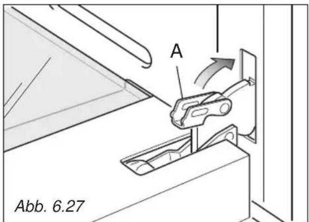
text_image
A Abb. 6.27Einbau-Anleitung
WICHTIG
natural_image
Technical line drawing of a structural support frame with mounting holes and dashed lines indicating hidden edges (no text or symbols)
natural_image
Line drawing of two people assembling a large oven on a tiled floor (no text or symbols)Abb. 7.4

text_image
C# C# GENERATION Abb. 7.5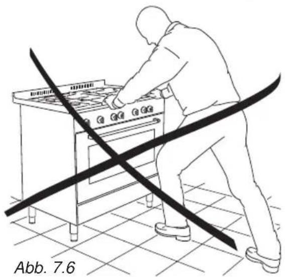
natural_image
Line drawing of a person using a stove with crossed lines indicating resistance or work (no text or symbols)KÜCHENHERD TRANSPORTIEREN
HINWEIS
natural_image
Mechanical assembly diagram showing a rotating shaft and housing with directional arrows indicating motion (no text or symbols)ANTI-KIPP-HALTERUNG
natural_image
Technical line drawing of a cabinet with an open door and a cross mark, labeled Abb. 7.8 (no text or symbols on the diagram itself)natural_image
Line drawing of hands using a wrench to tie a rope or cable (no text or symbols present)
Kat: II 2E+3+
natural_image
Line drawing of hands using a wrench to lift a vertical pipe (no text or symbols)WICHTIG:
text_image
Technical diagram showing a hand using a tool to adjust or install a mechanical component, with labeled parts 'J' and a tool handle.- Prescriptions de la Directive 93/68/CEE;
- Prescriptions de la Directive 2011/65/UE.

text_image
CE FR BEPRECAUTIONS DE SECURITE ET CONSEILS IMPORTANTS
natural_image
Symbol of a trash bin crossed with no text or numbers, representing waste sorting or restriction (no text present)
text_image
Warning sign set with three triangular warning symbols: exclamation mark, flame symbol, and steam train.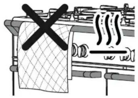
text_image
Diagram showing a kitchen with a crossed-out cloth and steam rising, indicating a warning or hazard.ATTENTION – TRÈS IMPORTANT !
DANGER D'INCENDIE/SURCHAUFFE:
natural_image
Diagram of a stylized object with concentric circles and scattered dots, labeled Fig. 3.1 (no text or symbols on the object itself)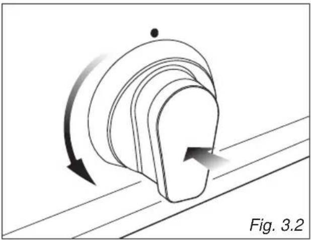
natural_image
Diagram of a curved mechanical component with directional arrows indicating motion, labeled Fig. 3.2 (no text or symbols on the diagram itself)natural_image
Symmetrical abstract diagram with concentric circles and decorative elements, no text or symbols present
natural_image
Diagram of a curved mechanical component with directional arrows indicating motion, labeled Fig. 3.4a (no text or symbols on the diagram itself)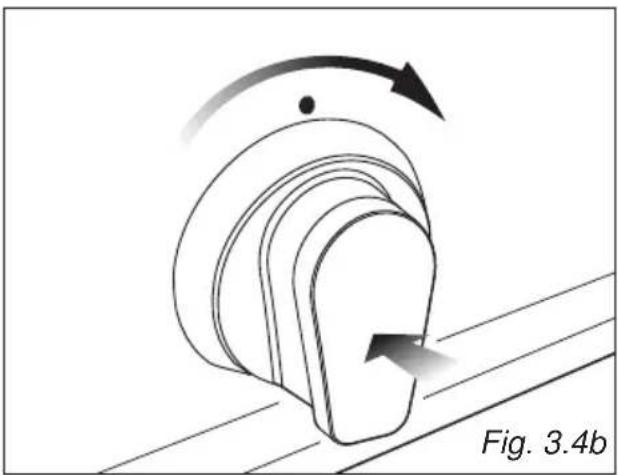
natural_image
Diagram of a mechanical component with curved arrows indicating motion, labeled Fig. 3.4b (no text or symbols on the diagram itself)Attention
text_image
Diagram illustrating three-step assembly process: top-down, cross-section, and final step with checkmark
text_image
S T Fig. 6.3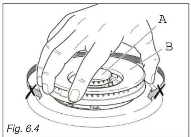
text_image
A B Fig. 6.4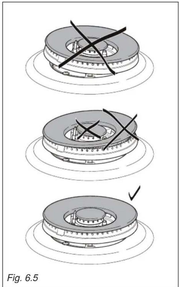
natural_image
Three-step diagram showing a mechanical assembly with cross marks, no text or symbols presentMONTAGE ET DEMONTAGE DES CHASSIS LATERAUX
natural_image
Technical line drawing of a door with a hand inserting a component into the interior (no text or symbols)Fig. 6.7
SUPPORT DE GRILLE COULISSANT TÉLESCOPIQUE (fig. 6.8)
natural_image
Technical line drawing of a heat exchanger or cooling unit (no text or symbols)Fig. 6.11 Fig. 6.10 Barrage de protection
natural_image
Technical line drawing of a mechanical component with two parallel plates and mounting brackets (no text or symbols)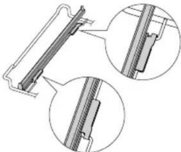
natural_image
Technical line drawing of a mechanical component with two circular inset views showing internal detail (no text or symbols)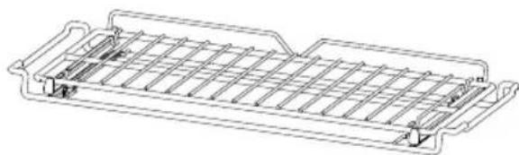
natural_image
Technical line drawing of a rectangular grid structure with internal channels and mounting points (no text or symbols)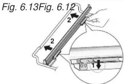
text_image
Fig. 6.13Fig. 6.12 2 2 4 1REPLACEMENT DE LA LAMPE DU FOUR
natural_image
Technical line drawing of a mechanical assembly with mounting feet and a transparent panel (no text or symbols)MONTAGE ET DEMONTAGE DE LA VITRE INTERIEURE POUR LE NETTOYAGE
natural_image
Technical line drawing of a mechanical bracket assembly (no text or symbols)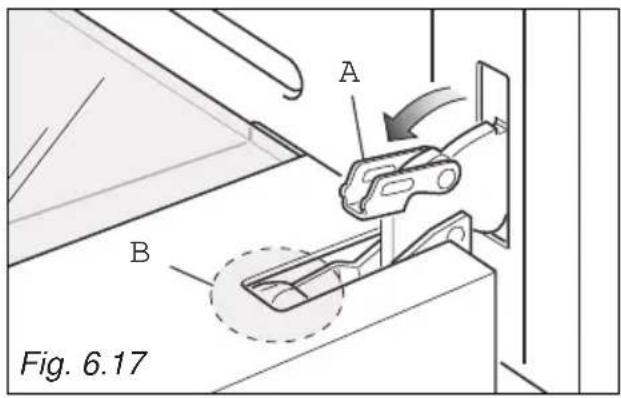
text_image
A B Fig. 6.17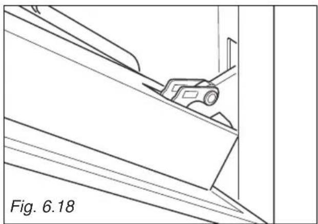
natural_image
Technical line drawing of a mechanical component on an inclined plane, labeled Fig. 6.18 (no text or symbols on the diagram itself)
natural_image
Line drawing of a person installing or adjusting a panel on a door frame (no text or symbols)DEMONTAGE DE LA PORTE DU FOUR
text_image
Warning symbol illustration showing a warning triangle with an exclamation mark and a hand holding a glove, alongside a crossed-out hand.
text_image
C Fig. 6.20DEMONTAGE DE LA VITRE INTERIEURE
natural_image
Illustration of a device being handled with two hands, showing internal components and motion arrows (no text or symbols)APRES LE NETTOYAGE, REMONTER LA VITRE INTERIEURE
natural_image
Line drawing of two hands holding a wooden plank, labeled Fig. 6.25 (no text or symbols on the diagram itself)
natural_image
Technical diagram showing a mechanical component with an arrow indicating motion, labeled Fig. 6.26 (no text or symbols on the diagram itself)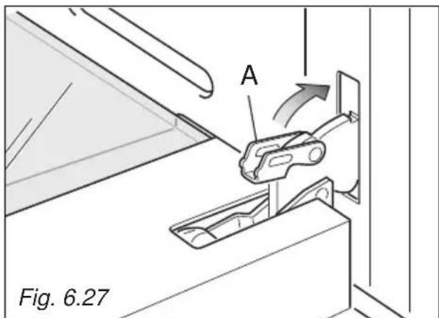
text_image
A Fig. 6.27natural_image
Technical line drawing of a structural support frame with mounting holes and dashed lines indicating hidden edges (no text or symbols)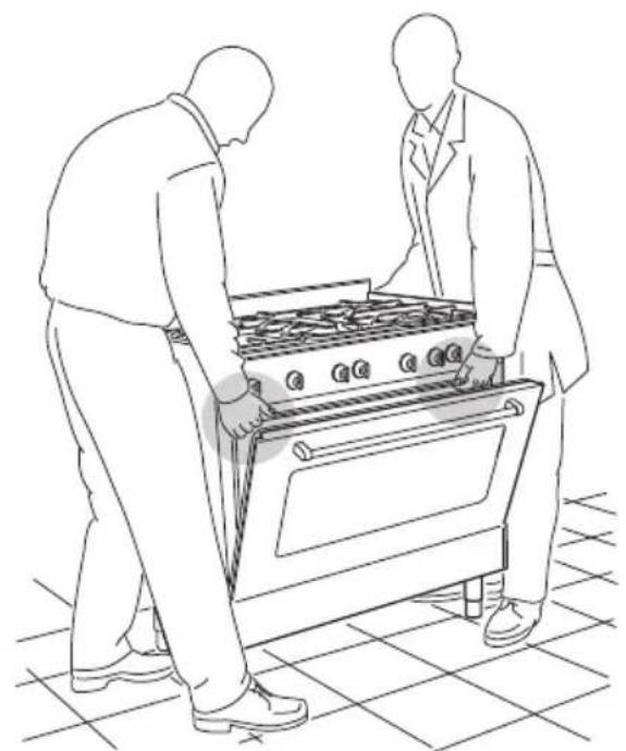
natural_image
Line drawing of two people assembling a large oven on a tiled floor (no text or symbols)Fig. 7.4
text_image
City of Generation Fig. 7.5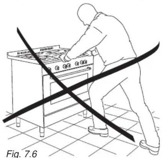
natural_image
Line drawing of a person using a portable stove with diagonal lines indicating crossed-out or unulged components (no text or symbols)DEPLACEMENT DE LA CUISINIERE
AVERTISSEMENT
natural_image
Diagram of a mechanical assembly with directional arrows indicating motion, labeled Fig. 7.7 (no text or symbols on the diagram itself)ÉQUERRE ANTI-BASCULEMENT
natural_image
Technical line drawing of a cabinet with an open door and a warning symbol, labeled Fig. 7.8 (no text or symbols on the diagram itself)CONDITIONS A L'EGARD DE LA VENTILATION
EVACUATION DES PRODUITS DE COMBUSTION
natural_image
Illustration of hands using a wrench to tie a pipe, labeled Fig. 8.3 (no text or symbols on the diagram itself)natural_image
Illustration of hands using a wrench to adjust a vertical pipe (no text or symbols present)IMPORTANT:
text_image
Technical diagram showing a hand using a tool to lift a mechanical component, labeled with 'J' and part number '1'natural_image
Technical line drawing of a mechanical clamp or connector assembly, labeled 'F', with no readable text or symbols beyond the label and figure number 'Fig. 9.2' (no technical annotations)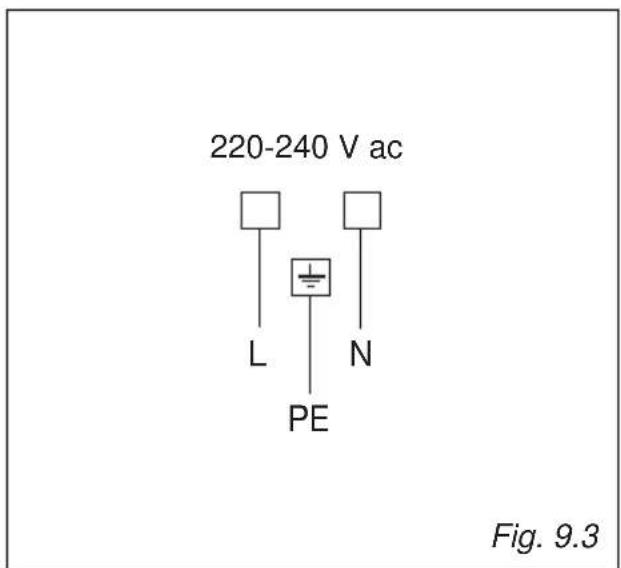
text_image
220-240 V ac L N PE Fig. 9.3Dear Customer,
Thank you for having purchased and given your preference to our product.
The safety precautions and recommendations reported below are for your own safety and that of others. They will also provide a means by which to make full use of the features offered by your appliance.
Please preserve this booklet carefully. It may be useful in future, either to yourself or to others in the event that doubts should arise relating to its operation.
This appliance must be used only for the task it has explicitly been designed for, that is for cooking foodstuffs. Any other form of usage is to be considered as inappropriate and therefore dangerous.
The manufacturer declines all responsibility in the event of damage caused by improper, incorrect or illogical use of the appliance.
DECLARATION OF CE CONFORMITY
- This appliance has been designed to be used only for cooking. Any other use (such as heating a room) is improper and dangerous.
- This appliance has been designed, constructed, and marketed in compliance with:
- Safety requirements of the “Gas” Directive 2009/142/EC (until the 20/04/2018) OR Regulation (EU) 2016/426 (starting from the 21/04/2018);
- Safety requirements of the "Low voltage" Directive 2014/35/EU;
- Safety requirements of the "EMC" Directive 2014/30/EU;
- Requirements of EU Directive 93/68/EEC;
- Requirements of EU Directive 2011/65/EU.
text_image
CE NL BE FRIMPORTANT SAFETY PRECAUTIONS AND RECOMMENDATIONS
IMPORTANT: This appliance is designed and manufactured solely for the cooking of domestic (household) food and is not suitable for any non domestic application and therefore should not be used in a commercial environment.
The appliance guarantee will be void if the appliance is used within a non domestic environment i.e. a semi commercial, commercial or communal environment.
Read the instructions carefully before installing and using the appliance.
- This appliance has been designed and manufactured in compliance with the applicable standards for the household cooking products and it fulfills all the safety requirements shown in this manual, including those for surface temperatures.
Some people with sensitive skin may have a more pronounced temperature perception with some components although these parts are within the limits allowed by the norms.
The complete safety of the appliance also depends on the correct use, we therefore recommend to always pay a extreme attention while using the product, especially in the presence of children.
• After having unpacked the appliance, check to ensure that it is not damaged and that the oven door closes correctly.
In case of doubt, do not use it and consult your supplier or a professionally qualified technician.
- Packing elements (i.e. plastic bags, polystyrene foam, nails, packing straps, etc.) should not be left around within easy reach of children, as these may cause serious injuries.
- Some appliances are supplied with a protective film on steel and aluminium parts. This film must be removed before using the appliance.
- IMPORTANT: The use of suitable protective clothing/gloves is recommended when handling or cleaning this appliance.
- Do not attempt to modify the technical characteristics of the appliance as this may become dangerous to use. The manufacturer declines all responsibility for any inconvenience resulting from the inobservance of this condition.
- CAUTION: this appliance must only be installed in a permanently ventilated room in compliance with the applicable regulations.
- Do not operate your appliance by means of an external timer or separate remote-control system.
- Do not carry out cleaning or maintenance operations on the appliance without having previously disconnected it from the electric power supply.
- WARNING: Ensure that the appliance is switched off before replacing the oven lamp to avoid the possibility of electric shock.
- Do not use a steam cleaner because the moisture can get into the appliance therefore making it unsafe.
- Do not touch the appliance with wet or damp hands (or feet).
- Do not use the appliance whilst in bare feet.
- If you should decide not to use this appliance any longer (or decide to substitute another model), before disposing of it, it is recommended that it be made inoperative in an appropriate manner in accordance to health and environmental protection regulations, ensuring in particular that all potentially hazardous parts be made harmless, especially in relation to children who could play with unused appliances.
- The various components of the appliance are recyclable. Dispose of them in accordance with the regulations in force in your country. If the appliance is to be scrapped, remove the power cord.
• After use, ensure that the knobs are in the off position. - Children less than 8 years of age shall be kept away unless continuously supervised.
- This appliance can be used by children aged from 8 years and above and persons with reduced physical, sensory or mental capabilities or lack of experience and knowledge if they have been given supervision or instruction concerning use of the appliance in a safe way and understand the hazards involved. Children shall not play with the appliance. Cleaning and user maintenance shall not be made by children without supervision.
- The manufacturer declines all liability for injury to persons or damage to property caused by incorrect or improper use of the appliance.
- WARNING: During use the appliance and its accessible parts become hot; they remain hot for some time after use.
- Care should be taken to avoid touching heating elements (on the hob and inside the oven).
- The door is hot, use the handle.
- To avoid burns and scalds, young children should be kept away.
- Make sure that electrical cables connecting other appliances in the proximity of the cooker cannot come into contact with the hob or become entrapped in the oven door.
- WARNING: Unattended cooking on a hob with fat or oil can be dangerous and may result in fire. NEVER try to extinguish a fire with water, but switch off the appliance and then cover flame e.g. with a lid or a fire blanket.
- WARNING: Danger of fire: do not store items on the cooking surfaces.
- WARNING: When correctly installed, your product meets all safety requirements laid down for this type of product category. However special care should be taken around the rear or the underneath of the appliance as these areas are not designed or intended to be touched and may contain sharp or rough edges, that may cause injury.
- FIRST USE OF THE OVEN - it is advised to follow these instructions:
– Furnish the interior of the oven as described in the chapter "CLEANING AND MAINTENANCE".
- Switch on the empty oven on max to eliminate grease from the heating elements.
- Disconnect the appliance from the electrical power supply, let the oven cool down and clean the interior of the oven with a cloth soaked in water and neutral detergent; then dry carefully.
- CAUTION: Do not use harsh abrasive cleaners or sharp metal scrapers to clean the oven door glass since they can scratch the surface, which may result in shattering of the glass.
- Do not line the oven walls or base with aluminium foil. Do not place baking trays or the drip tray on the base of the oven chamber.
- FIRE RISK! Do not store flammable material in the oven or in the storage compartment.
- Always use oven gloves when removing the shelves and food trays from the oven whilst hot.
- Do not hang towels, dishcloths or other items on the appliance or its handle – as this could be a fire hazard.
- Clean the oven regularly and do not allow fat or oils to build up in the oven base or tray. Remove spillages as soon as they occur.
- Do not stand on the cooker or on the open oven door.
- Always stand back from the appliance when opening the oven door to allow steam and hot air to escape before removing the food.
- SAFE FOOD HANDLING: Leave food in the oven for as short a time as possible before and after cooking. This is to avoid contamination by organisms which may cause food poisoning. Take particular care during warmer weather.
- WARNING: Take care NOT to lift the cooker by the door handle.
- CAUTION: The cooking process has to be supervised. A short term cooking process has to be supervised continuously.
- The appliance must not be installed behind a decorative door in order to avoid overheating.
- The oven accessories (e.g. oven wire rack) must be fitted correctly as indicated at page 209 and 210.
- If the power supply cable is damaged, it must be replaced only by an authorized service agent in order to avoid a hazard.
ENERGY LABELLING/ECODESIGN
- Commission delegated regulation (EU) No 65/2014 (supplementing Directive 2010/30/EU of the European Parliament and of the Council).
- Commission regulation (EU) No 66/2014 (implementing Directive 2009/125/EC of the European Parliament and of the Council).
Reference to the measurement and calculation methods used to establish compliance with the above requirements:
• Standard EN 60350-1 (electric ovens). - Standard EN30-2-1 (hobs: gas fired burners).
USE OF THE APPLIANCE, ENERGY SAVING TIPS
OVEN
- Check the oven door always closes properly and the door gasket is clean and in order. During use, open the oven door only when strictly necessary to avoid heat losses (for some functions it may be necessary to use the oven with the door half-closed, check the oven operating instructions).
- Turn off the oven 5-10 minutes before the end of the theoretical cooking time to recuperate the stored heat.
- We recommend using oven proof dishes and adjusting the oven temperature during cooking if necessary.
HOB
GAS FIRED BURNERS
- It is important that the diameter of the pot be suitable to the potentiality of the burner so as not to compromise the high output of the burners and therefore energy waste. A small pot on a large burner does not give you a boiling point in a shorten amount of time since the capacity of heat absorption of a liquid mass depends on the volume and the surface of the pot.
- Avoid keeping a burner on without something on it (without pot).
IMPORTANT INFORMATION FOR CORRECT DISPOSAL OF THE PRODUCT IN ACCORDANCE WITH EC DIRECTIVE 2012/19/EC.
At the end of its working life, the product must not be disposed of as urban waste. It must be taken to a special local authority differentiated waste collection centre or to a dealer providing this service.
Disposing of a household appliance separately avoids possible negative consequences for the environment and health deriving from inappropriate disposal and enables the constituent materials to be recovered to obtain significant savings in energy and resources. As a reminder of the need to dispose of household appliances separately, the product is marked with a crossed-out wheeled dustbin.
natural_image
Symbol of a trash bin crossed with a diagonal line, representing no waste or discharge (no text or numbers present)

text_image
Warning sign set with three triangular warning symbols: exclamation mark, flame symbol, and steam train.
text_image
Diagram showing a kitchen with a crossed-out cloth and steam lines, indicating a warning or hazard.WARNING – VERY IMPORTANT!
FIRE/OVERHEATING HAZARD:
- Do not place towels/cloths etc onto the hob rail or oven door handle/s whilst the product is in use or hot.
TO AVOID DAMAGE TO THE APPLIANCE:
- Do not lift/move the cooker by the hob rail or oven door handle/s.
- Do not lean on the hob rail or oven door handle/s.
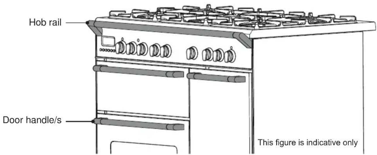
text_image
Hob rail Door handle/s This figure is indicative onlyFig. 1.1
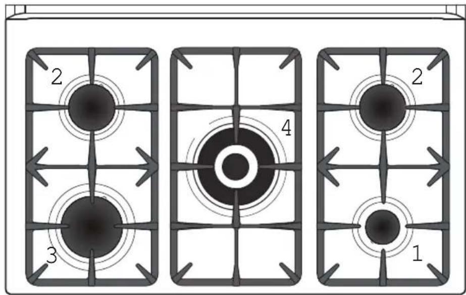
text_image
2 3 4 1 2COOKING HOB
- Auxiliary burner (A) 1,00 kW
- Semi-rapid burner (SR) 1,75 kW
- Rapid burner (R) 3,00 kW
- Dual burner (D) 4,00 kW
Notes:
• The electric ignition is incorporated in the knobs.
- The appliance has a safety valve system fitted, the flow of gas will be stopped if and when the flame should accidentally go out.
CAUTION:
If the burner is accidentally extinguished, turn the gas off at the control knob and wait at least 1 minute before attempting to relight.
CAUTION:
Gas hobs produce heat and humidity in the environment in which they are installed. Ensure that the cooking area is well ventilated by opening the natural ventilation grilles or by installing an extractor hood connected to an outlet duct that vents to the outside.
CAUTION:
If the hob is used for a prolonged time it may be necessary to provide further ventilation by opening a window or by increasing the suction power of the extractor hood (if fitted).

text_image
Fig. 2.1 22:38 8 7 6 5 4 3 2 1CONTROL PANEL - Controls description
- Front right burner control knob
- Rear right burner control knob
- Central burner control knob
- Rear left burner control knob
- Front left burner control knob
- Multifunction oven thermostat knob
- Multifunction oven switch knob
- Electronic clock/programmer
Pilot lamp:
- Multifunction oven temperature indicator light
Note:
Your appliance has been fitted with a cooling fan to achieve optimum efficiency of the controls and to ensure lower surface temperatures are maintained.
When the oven is operating the cooling fan motor switches ON/OFF depending on temperature. Depending on cooking temperatures and times, the cooling fan may run on even after appliance has been switched off. The duration of this time is dependent on previous cooking temperature and duration.
GAS BURNERS
(Auxiliary, Semi-rapid and Rapid)
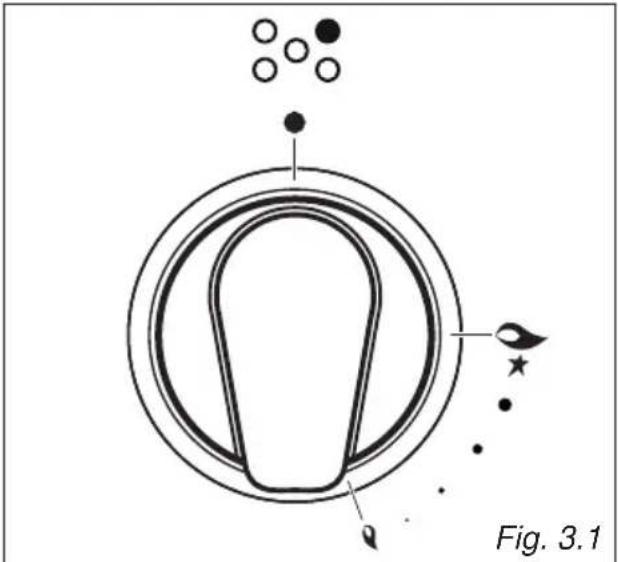
Gas flow to the burners is adjusted by turning the knobs (illustrated in fig. 3.1) which control the valves.
Turning the knob so that the symbols printed on itself point to the symbol printed on the control panel achieves the following functions.
The maximum aperture position permits rapid boiling of liquids, whereas the minimum aperture position allows simmer warming of food or maintaining boiling conditions of liquids.
To reduce the gas flow to minimum, rotate the knob further anti-clockwise to point the indicator towards the ⏻ position.
Other intermediate operating adjustments can be achieved by positioning the indicator between the maximum and minimum aperture positions, and never between the maximum aperture and ●positions.
| Knob position | Function | AUXILIARY, SEMI-RAPID AND RAPID burner |
| [9803] | Closed valve | 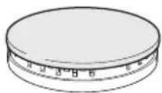 |
 | Maximum rate | 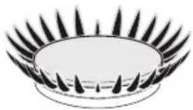 |
| [HCTX] | Minimum rate | 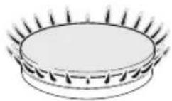 |
LIGHTING GAS BURNERS FITTED WITH SAFETY VALVE DEVICE
(Auxiliary, Semi-rapid and Rapid burners)
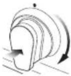
In order to light the burner, you must:
- Push and turn the knob in an anticlockwise direction up to the position (maximum rate), push in and hold the knob until the flame has been lit (fig. 3.2).
The sparks produced by the lighter situated inside the relative burner will light the flame.
In the event that the local gas supply conditions makes it difficult to light the burner in ⚠️★ position, try again with the knob in ⚠️ position.
If there is no main electrical supply, bring a lighted match close to the burner.
-
Wait for about ten seconds after the gas burner has been lit before letting go the knob (safety device activation delay).
-
Adjust the gas valve to the desired position.
If the burner flame should go out for some reason, the safety valve will automatically stop the gas flow.
To re-light the burner, return the knob to the closed ●position, wait for at least 1 minute and then repeat the lighting procedure.
natural_image
Diagram of a circular object with internal structure and surrounding dots and stars, labeled Fig. 3.1 (no text or symbols on the diagram itself)
natural_image
Diagram of a curved mechanical component with directional arrows indicating motion, labeled Fig. 3.2 (no text or symbols on the diagram itself)Caution!
Do not cover the hob with aluminium foils.
N.B. When the cooker is not being used, set the gas knobs to their closed positions and also close the cock valve on the gas bottle or the main gas supply line.
Caution!
The cooking hob becomes very hot during operation.
Keep children well out of reach.
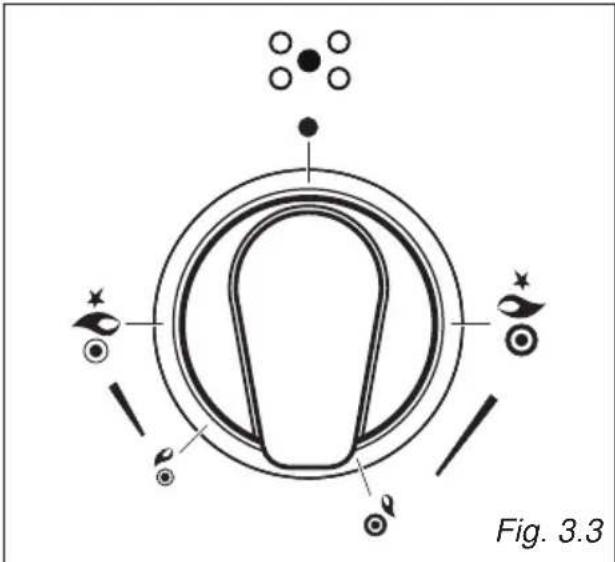
GAS BURNERS (Dual)
The Dual Burner is a very flexible burner which allows different regulations and optimal cooking.
It is composed by one inner and one outer crown; the flame of the inner crown can be regulated separately from the flames of the outer crown.
The Dual Burner can be used:
- turn the knob clockwise - as a small burner (flame produced only by the inner crown) which can be adjusted from the maximum ( ) to the minimum ( ) position. Intermediate operating adjustments can be achieved by positioning the indicator between the maximum and minimum opening positions, and never between the maximum opening and position.
- turn the knob anticlockwise - as a high-power burner (all flames produced simultaneously by inner and outer crown) which can be adjusted from the maximum (★) to the minimum (○) position. Intermediate operating adjustments can be achieved by positioning the indicator between the maximum and minimum opening positions, and never between the maximum opening and ● position.
Gas flow to the burner is adjusted by turning the knob (illustrated in fig. 3.3) which controls the valves.
| Knob position Function DUAL burner | |||
 | Closed valve | 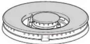 | |
 |  | Maximum rate of inner crown (only inner flame at the maximum | 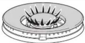 |
 | Minimum rate of inner crown (only inner flame at the minimum) | 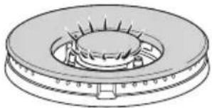 | |
 |  | Maximum rate of inner + outer crown (inside and outside flames in simultaneously at the maximum) | 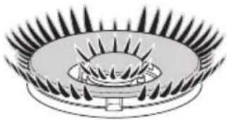 |
 | Minimum rate of inner + outer crown (inside and outside flames in simultaneously at the minimum) | 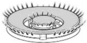 | |
LIGHTING GAS BURNERS FITTED WITH SAFETY VALVE DEVICE (Dual burner)
In order to light the burner, you must:
- Push and turn the knob in an clockwise or anticlockwise direction up to the Ⓞ position (maximum rate of inner crown) or ✕ position (max imum rate of inner + outer crown), push in and hold the knob until the flame has been lit (fig. 3.4a or 3.4b).
The sparks produced by the lighter situated inside the relative burner will light the flame.
In the event that the local gas supply conditions makes it difficult to light the burner in ⚙ or position, try again with the knob in ⚙ or position.
If there is no main electrical supply, bring a lighted match close to the burner. - Wait for about ten seconds after the gas burner has been lit before letting go the knob (safety device activation delay).
- Adjust the gas valve to the desired position.
If the burner flame should go out for some reason, the safety valve will automatically stop the gas flow.
To re-light the burner, return the knob to the closed ●position, wait for at least 1 minute and then repeat the lighting procedure.
N.B. When the cooker is not being used, set the gas knobs to their closed positions and also close the cock valve on the gas bottle or the main gas supply line.
natural_image
Symmetrical abstract diagram with concentric circles and decorative elements, no text or symbols present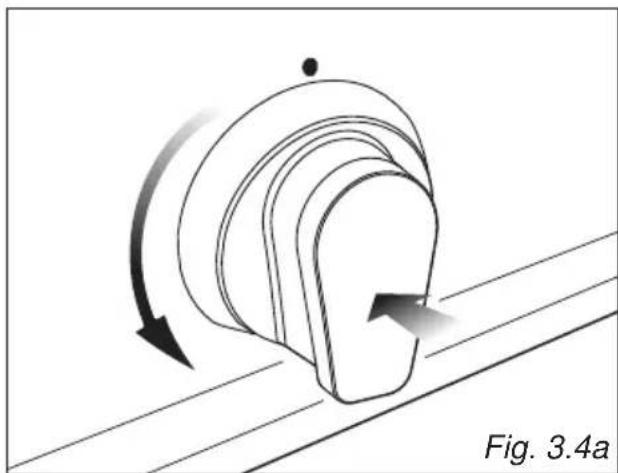
natural_image
Diagram of a curved mechanical component with directional arrows indicating motion, labeled Fig. 3.4a (no text or symbols on the diagram itself)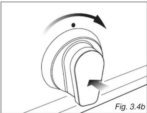
natural_image
Diagram of a mechanical component with curved arrows indicating motion, labeled Fig. 3.4b (no text or symbols on the diagram itself)Caution!
The cooking hob becomes very hot during operation.
Keep children well out of reach.
CHOICE OF THE BURNER
On the control panel, near every knob there is a diagram that indicates which burner is controlled by that knob.
The suitable burner must be chosen according to the diameter and the capacity used. As an indication, the burners and the pots must be used in the following way:
DIAMETERS OF PANS WHICH MAY BE USED ON THE BURNERS
| BURNERS MINIMUM MAXIMUM | ||
| Auxiliary 6 cm | 14 cm | |
| Semi-rapid 16 cm | 24 cm | |
| Rapid 24 cm | 26 cm | |
| Dual (with ONLY inner crown operating) 6 cm | 14 cm | |
| Dual (with inner + outer crown operating) 26 cm | 28 cm | |
| Maximum diameter for woks: 36 cm | ||
| do not use pans with concave or convex bases | ||
natural_image
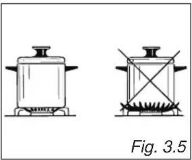
Two identical line drawings of a cooking pot with a lid and a square base, both without any text or symbols.It is important that the diameter of the pot be suitable to the potentiality of the burner so as not to compromise the high output of the burners and therefore energy waste.
A small pot on a large burner does not give you a boiling point in a shorter amount of time since the capacity of heat absorption of a liquid mass depends on the volume and the surface of the pot.
CORRECT USE OF THE DUAL BURNER (fig. 3.6a - 3.6b)
The flat-bottomed pans are to be placed directly onto the pan-support.
When using a WOK you need to place the supplied stand in the burner to avoid any faulty operation of the dual burner (figs. 3.6a - 3.6b).
IMPORTANT:
The special grille for wok pans (fig. 3.6b) MUST BE PLACED ONLY over the pan-rest for the dual burner.

text_image
WRONG CORRECT Fig. 3.6a Fig. 3.6b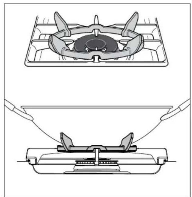
natural_image
Technical line drawing showing two stages of a gas stove heating process, with no text or symbols present.Attention: the oven door becomes very hot during operation. Keep children away.
GENERAL FEATURES
As its name indicates, this is an oven that presents particular features from an operational point of view.
In fact, it is possible to insert 8 different programs to satisfy every cooking need.
The 8 positions, thermostatically controlled, are obtained by 4 heating elements which are:
- Bottom element
- Top element
- Grill element
- Circular element
NOTE:
Upon first use, it is advisable to operate the oven for 30 minutes in the position and for another 30 minutes at the maximum temperature (thermostat knob on position 250) in the positions and, to eliminate possible traces of grease on the heating elements.
Clean the oven and accessories with warm water and washing-up liquid.
WARNING:
The door is hot, use the handle.
During use the appliance becomes hot. Care should be taken to avoid touching heating elements inside the oven.
OPERATING PRINCIPLES
Heating and cooking in the MULTI-FUNCTION oven are obtained in the following ways:
a. by normal convection
The heat is produced by the upper and lower heating elements.
b. by forced convection
A fan sucks in the air contained in the oven muffle, which sends it through the circular heating element and then sends it back through the muffle. Before the hot air is sucked back again by the fan to repeat the described cycle, it envelops the food in the oven, provoking a complete and rapid cooking. It is possible to cook several dishes simultaneously.
c. by semi-forced convection
The heat produced by the upper and lower heating elements is distributed throughout the oven by the fan.
d. by radiation
The heat is irradiated by the infra red grill element.
e. by radiation and ventilation
The irradiated heat from the infra red grill element is distributed throughout the oven by the fan.
f. by ventilation
The food is defrosted by using the fan only function without heat.
text_image
F Fig. 4.1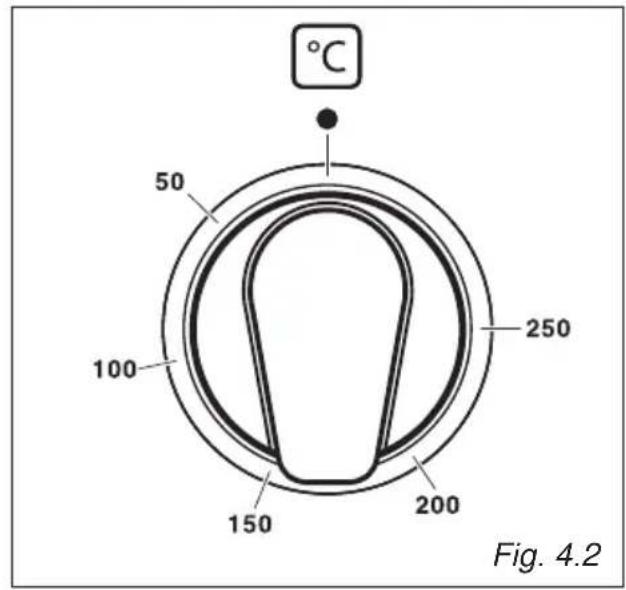
text_image
°C 50 100 250 150 200 Fig. 4.2THERMOSTAT KNOB (fig. 4.2)
To turn on the heating elements of the oven, set the switch knob on the desired program and the thermostat knob onto the desired temperature.
To set the temperature, it is necessary to make the knob indicator meet the chosen number.
The elements will turn ON or OFF automatically according to the energy need which is determined by the thermostat.
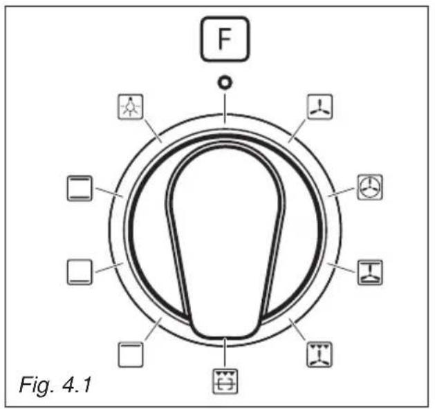
FUNCTION SELECTOR KNOB (fig. 4.1)
Rotate the knob clockwise to set the oven for one of the following functions:

OVEN LIGHT
By turning the knob onto this setting we light the oven cavity.
The oven remains alight while any of the functions is on.

TRADITIONAL CONVECTION COOKING
The upper and lower heating elements are switched on. The heat is diffused by natural convection and the temperature must be regulated between 50^ C and 250^ C with the thermostat knob.
It is necessary to preheat the oven before introducing the foods to be cooked.
Recommended for:
For foods which require the same cooking temperature both internally and externally, i.e. roasts, spare ribs, meringue, etc.

LOWER HEATING ELEMENT
In this position only the lower element is switched on.
Heat is distributed by natural convection.
The temperature must be regulated between 50 °C and the maximum position with the thermostat knob.
Recommended for:
To complete cooking of dishes that require higher temperature at the bottom.

UPPER HEATING ELEMENT
In this position only the upper element is switched on.
Heat is distributed by natural convection.
The temperature must be regulated between 50 °C and the maximum position with the thermostat knob.
Recommended for:
To complete cooking of dishes that require higher temperature at the top.

GRILLING
The infra-red heating element is switched on.
The heat is diffused by radiation.
Use with the oven door closed and with the thermostat knob to between 50 and 225°C.
In the position also the rotisserie motor come on for cooking with the rotisserie.
For correct use see chapter "USE OF THE GRILL" and "USE OF THE ROTISSERIE"
Note: It is recommended that you do not grill for longer than 30 minutes at any one time.
Attention: the oven door becomes very hot during operation. Keep children away.
Recommended for:
Intense grilling action for cooking with a broiler; browning, crisping, "au gratin", toasting, etc.

VENTILATED GRILL COOKING
The infra-red ray grill and the fan are on.
The heat is mainly diffused by radiation and the fan then distributes it throughout the oven.
The temperature must be regulated between 50^ C and 225^ C maximum for max 30 minutes, with the thermostat knob.
It is necessary to preheat the oven for about 5 minutes.
For correct use see chapter "GRILLING AND AU GRATIN".
Use with the oven door closed.
Attention: The oven door becomes very hot during operation. Keep children away.
Recommended for:
For grill cooking when a fast outside browning is necessary to keep the juices in, i. e. veal steak, steak, hamburger, etc.

CONVECTION COOKING WITH VENTILATION
The upper and lower heating elements and the fan turn on.
The heat coming from the top and bottom is diffused by forced convection.
The temperature must be regulated between 50° and 250 °C with the thermostat knob.
Recommended for:
For foods of large volume and quantity which require the same internal and external degree of cooking; for ie: rolled roasts, turkey, legs, cakes, etc.

HOT AIR COOKING
The circular element and the fan are on. The heat is diffused by forced convection and the temperature must be regulated between 50^ and 250^ C with the ther mostat knob. It is not necessary to preheat the oven.
Recommended for:
For foods that must be well done on the outside and tender or rare on the inside, i. e. lasagna, lamb, roast beef, whole fish, etc.

DEFROSTING FROZEN FOODS
Only the oven fan is on. To be used with the thermostat knob on “●” because the other positions have no effect. The defrosting is done by simple ventilation without heat.
Recommended for:
To rapidly defrost frozen foods; 1 kilogram requires about one hour.
The defrosting times vary according to the quantity and type of foods to be defrosted.
COOKING ADVICE
STERILIZATION
Sterilization of foods to be conserved, in full and hermetically sealed jars, is done in the following way:
a. Set the switch to position ☐
b. Set the thermostat knob to position 185^ C and preheat the oven.
c. Fill the dripping pan with hot water.
d. Set the jars onto the dripping pan making sure they do not touch each other and the door and set the thermostat knob to position 135 °C.
When sterilization has begun, that is, when the contents of the jars start to bubble, turn off the oven and let cool.
REGENERATION
Set the switch to position 📁 and the thermostat knob to position 150°C.
Bread becomes fragrant again if wet with a few drops of water and put into the oven for about 10 minutes at the highest temperature.
ROASTING
To obtain classical roasting, it is necessary to remember:
- that it is advisable to maintain a temperature between 180 and 200 °C.
- that the cooking time depends on the quantity and the type of foods.
SIMULTANEOUS COOKING OF DIFFERENT FOODS
The MULTI-FUNCTION oven set on position 🏠 and 🔒 gives simultaneous heterogeneous cooking of different foods.
Different foods such as fish, cake and meat can be cooked together without mixing the smells and flavours.
This is possible since the fats and vapors are oxidized while passing through the electrical element and therefore are not deposited onto the foods.
The only precautions to follow are:
- The cooking temperatures of the different foods must be as close to as possible, with a maximum difference of 20^ - 25^ .
- The introduction of the different dishes in the oven must be done at different times in relation to the cooking times of each one.
The time and energy saved with this type of cooking is obvious.
GRILLING AND "AU GRATIN"
Set the switch to position
Set the thermostat to position 225 °C and after having preheated the oven, simply place the food on the shelf.
Close the door and let the oven operate with the thermostat on, until grilling is complete. Adding a few dabs of butter before the end of the cooking time gives the golden “au gratin” effect.
Note: It is recommended that you do not grill for longer than 30 minutes at any one time.
ATTENTION: the oven door becomes very hot during operation.
Keep children away.
USE OF THE GRILL
Preheat the oven for about 5 minutes.
Introduce the food to be cooked, positioning the rack as close to the grill as possible.
The dripping pan should be placed under the rack to catch the cooking juices and fats.
Grilling with the oven door closed.
Do not grill for longer than 30 minutes at any one time.
CAUTION: the oven door becomes very hot during operation. Keep children well out of reach.
OVEN COOKING
Before introducing the food, preheat the oven to the desired temperature.
For a correct preheating operation, it is advisable to remove the tray from the oven and introduce it together with the food, when the oven has reached the desired temperature.
Check the cooking time and turn off the oven 5 minutes before the theoretical time to recuperate the stored heat.
COOKING EXAMPLES
Temperatures and times are approximate as they vary depending on the quality and amount of food.
Remember to use ovenproof dishes and to adjust the oven temperature during cooking if necessary.
DISHES
TEMPERATURE
Cakes 180°C
Doughnuts 180°C
Potatoes in milk 200°C
Chicken breasts in tomato 200°C
Sole fish filet 200°C
Whiting 200°C
Cream puffs 200°C
Plum pie 200°C
Meat balls 200°C
Veal meatloaf 200°C
Grilled chicken - roast chicken 220°C
Baked lasagna 220°C
Roast beef 220°C
Oven cooked pasta 220°C
Lemon cake 220°C
Rice creol 225°C
Baked onions 225°C
Stuffed potatoes 225°C
Grilled veal joint 225°C
Marmalade pie 225°C
Pound cake 225°C
Turkish shishkebab 250°C
Pizza with anchovies 250°C

ELECTRONIC PROGRAMMER
The electronic programmer is a device which groups together the following functions:
• 24 hours clock with illuminated display
• Timer (up to 23 hours and 59 minutes)
• Program for automatic oven cooking
• Program for semi-automatic oven cooking
Description of the buttons:

Timer

Cooking time

End of cooking time

Manual position and cancellation of e inserted cooking program
To increase the numbers on the digital display
—To decrease the numbers on the digital display.
Description of the illuminated symbols:
AUTO - flashing - Programmer in automatic position but not programmed
AUTO - illuminated - Programmer in automatic position with program inserted.

Automatic cooking taking place

Timer in operation

and AUTO - flashing - Program error.
(The time of day lies between the calculated cooking start and end time).
Note:
Select a function by the respective button and, in 5 seconds, set the required time with the +/— buttons ("one-hand" operation). After a power cut the display resets to zero and cancels the set programs.

text_image
20:38 Fig. 5.1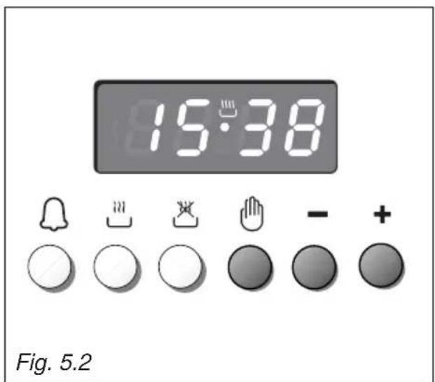
text_image
15:38 Fig. 5.2ELECTRONIC CLOCK (fig. 5.2)
The programmer is equipped with an electronic clock with illuminated numbers which indicates hours and minutes.
Upon immediate connection of the oven or after a power cut, three zeros will flash on the programmer display.
To set the correct time of day it is necessary to push the 📋 button and then the +r — button until you have set the correct time (fig. 5.2).
In another way push simultaneously the two buttons and at the same time push the or button.
Note: If the clock is reset it deletes any previously set programs
NORMAL COOKING WITHOUT THE USE OF THE PROGRAMMER
To manually use the oven, without the aid of the programmer, it is necessary to cancel the flashing AUTO by pushing the
button (AUTO will be switched off and the symbol 🎨 will illuminate - fig. 5.3).
Attention: If the AUTO is illuminated (which means a cooking program has already been inserted), by pushing the button you cancel the program and return to manual operation.
If the oven is switched on, you must switch off manually.
text_image
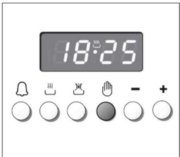
18:25ELECTRONIC TIMER
The timer program consists only of a buzzer which may be set for a maximum period of 23 hours and 59 minutes.
If the AUTO symbol is flashing push the button.
To set the time, push the 📁 button and the + or - until you obtain the desired time in the display (fig. 5.4).
Having finished the setting, the clock hour will appear on the panel and the symbol will be illuminated.
The countdown will start immediately and may be seen at any moment on the panel by simply pressing the button 🔒.
At the end of the time, the symbol will disappear and the buzzer will sound and continue for approximatley 7 minutes or until a button is pressed (not the + / — buttons). After a short time the display will revert back to the time of day.
SETTING THE FREQUENCY OF THE AUDIBLE SIGNAL
The buzzer has 3 different tones and can be changed by pressing the — button, but only when the time of day is displayed
text_image
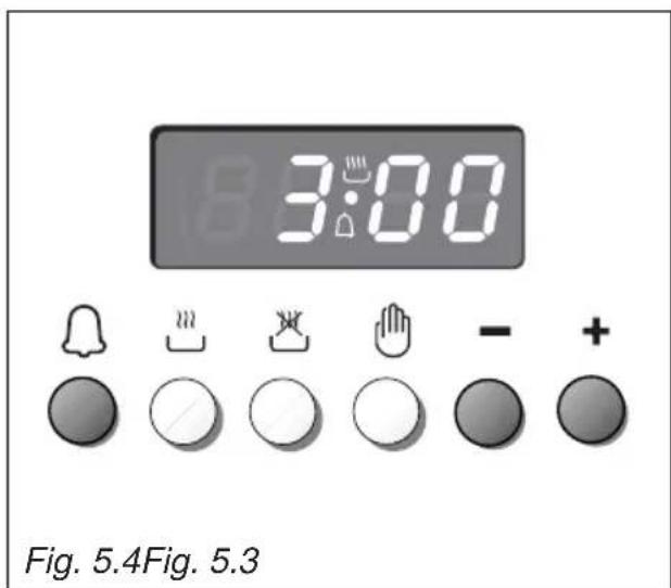
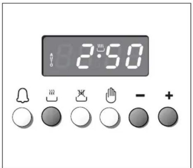
3:00 Fig. 5.4Fig. 5.3To cook food automatically in the oven, it is necessary to:
- Set the length of the cooking period.
- Set the end of the cooking time.
- Set the temperature and the oven cooking program.
These operations are done in the following way:
- Set the length of the cooking period by pushing the 🎨 button and the + button to increase, or -to decrease if you have passed the desired time (fig. 5.5). The AUTO and the 🎨 symbol will illuminate.
- Set the end of the cooking time by pressing the 📄 button (the cooking time already added to the clock time will appear), and the + button (fig. 5.6); if you pass the desired time you may get back by pushing the — button.
After this setting, the symbol will disappear. If after this setting, the AUTO flashes on the display and a buzzer sounds, it means there was an error in the programming, that is that the cooking cycle has been superimposed on the clock. In this case, modify the end of cooking time or the cooking period itself by following again the above mentioned instructions.
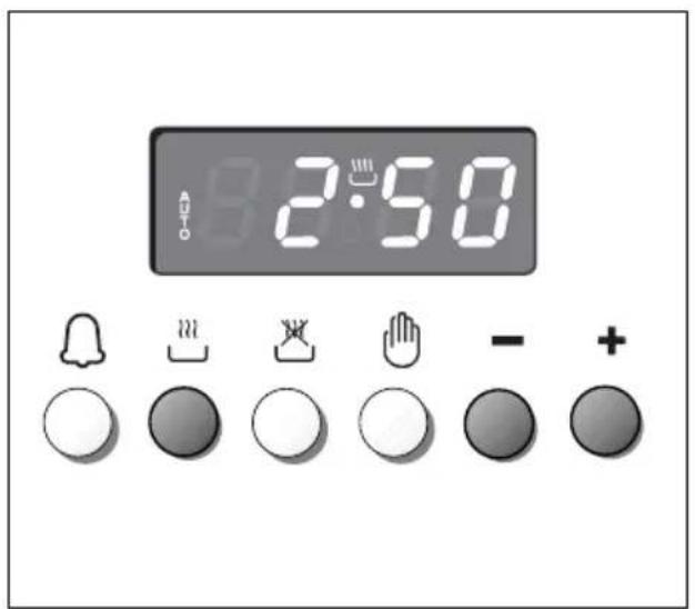
text_image
2:50- Set the temperature and the cooking program by using the switch and thermostat knobs of the oven (see specific chapters).
Now the oven is programmed and everything will work automatically, that is the oven will turn on at the right moment to end the cooking at the established hour.
During cooking, the ⏚ symbol remains illuminated.
By pushing the 📋 button you can see the time that remains until the end of cooking.
The cooking program may be cancelled at any time by pushing 🔒.
At the end of the cooking time the oven will turn off automatically, the ⏻ symbol will turn off, AUTO will flash and a buzzer will be sound, which can be turned off by pushing any of the buttons except the + / -buttons.
Turn the switch and thermostat knobs to zero and put the programmer onto "manual" by pressing the 🔊 button.
Attention: After a power cut the clock resets to zero and cancels the set programs.
After a power cut, three zeros will flash on the display.
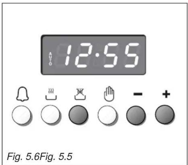
text_image
12:55 Fig. 5.6Fig. 5.5SEMI-AUTOMATIC COOKING
This is used to automatically switch off the oven after the desired cooking time has elapsed.
There are two ways to set your oven:
- Set the length of the cooking time by pushing the 🎨 button and the + button to advance, or —to go backwards if you have passed the desired time (fig. 5.7).
or
- Set the end of the cooking time by pushing the 🎨 button and the + button to advance, or —to go backwards if you have passed the desired time (fig. 5.8).
AUTO and the 🔊 symbol will be on.
Then set the temperature and the cooking programme using the oven switch and thermostat knobs (see specific chapters).
The oven is switched on and it will be switched off automatically at the end of the desired time.
During cooking, the 🎨 symbol remains on and by pressing the button 🎨 you can see the time that remains till the end of the cooking.
The cooking program may be cancelled at any time by pushing 🔒.
At the end of the cooking time the oven will turn off automatically, the 🎨 symbol will turn off, AUTO will flash and a buzzer will be sound, which can be turned off by pushing any of the buttons except the + / -buttons.
Turn the switch and thermostat knobs to zero and put the programmer onto "manual" by pressing the 🔊 button.
Attention: After a power cut the clock resets to zero and cancels the set programs.
After a power cut, three zeros will flash on the display.
text_image
2:50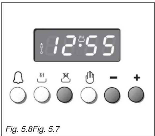
text_image
12:55 Fig. 5.8Fig. 5.7IMPORTANT – OVEN NOT WORKING
If the oven is not working, it may have been accidentally set to "AUTOMATIC" or the power to the appliance was interrupted. If the Timer is showing the letter "AUTO" as below or the time of day is flashing, the Oven may not turn on or be delayed in its operation.

text_image
12:55Before requesting a service call, please refer to the timer set up instructions in this handbook and ensure the timer is set to "MANUAL" operation ensuring the cook symbol 📋 appears in the timer as shown below.

text_image
15:38NB. A service charge will be made if an engineer is called out to re-set the timer, as this is not covered by the guarantee.

CLEANING AND MAINTENANCE
GENERAL ADVICE
- Before you begin cleaning, you must ensure that the appliance is disconnected from the electrical power supply.
- When the appliance is not being used, it is advisable to keep the gas tap closed.
- The periodical lubrication of the gas taps must be done only by specialized personnel.
- If a tap becomes stiff, do not force; contact your local After Sales Service Centre.
- It is advisable to clean when the appliance is cold and especially when cleaning the enamelled parts.
- Avoid leaving alkaline or acidic substances (lemon juice, vinegar, etc.) on the surfaces.
- Avoid using cleaning products with a chlorine or acidic base.
- Important: The use of suitable protective clothing/gloves is recommended when handling or cleaning of this appliance.
WARNING
When correctly installed, your product meets all safety requirements laid down for this type of product category. However special care should be taken around the rear or the underneath of the appliance as these areas are not designed or intended to be touched and may contain sharp or rough edges, that may cause injury.
ENAMELLED PARTS
All the enamelled parts must be cleaned with a sponge and soapy water or other non-abrasive products.
Dry preferably with a microfibre or soft cloth.
Acidic substances like lemon juice, tomato sauce, vinegar etc. can damage the enamel if left too long.
STAINLESS STEEL, ALUMINIUM PARTS, PAINTED AND SILK-SCREEN PRINTED SURFACES
Clean using an appropriate product.
Always dry thoroughly.
IMPORTANT: these parts must be cleaned very carefully to avoid scratching and abrasion. You are advised to use a soft cloth and neutral soap.
CAUTION: Do not use abrasive substances or non-neutral detergents as these will irreparably damage the surface.
Important: The manufacturer declines all liability for possible damage caused by the use of unsuitable products to clean the appliance.
Attention! The appliance gets very hot, mainly around the cooking areas. It is very important that children are not left alone in the kitchen when you are cooking.
Do not use a steam cleaner because the moisture can get into the appliance thus make it unsafe.
Do not use harsh abrasive cleaners or sharp metal scrapers to clean the oven door glass or the glass lid (models with glass lid only) since they can scratch the surface, which may result in shattering of the glass.
GAS TAPS
Periodic lubrication of the gas taps must be carried out by specialist personnel only. In the event of operating faults in the gas taps, call the Service Department.
INSIDE OF OVEN
The oven should always be cleaned after use when it has cooled down.
The cavity should be cleaned using a mild detergent solution and warm water. Suitable proprietary chemical cleaners may be used after first consulting with the manufacturers recommendations and testing a small sample of the oven cavity. Abrasive cleaning agents or scouring pads/cloths should not be used on the cavity surface.
NOTE: The manufacturers of this appliance will accept no responsibility for damage caused by chemical or abrasive cleaning.
Let the oven cool down and pay special attention no to touch the hot heating elements inside the oven cavity.
BURNERS
They can be removed and washed with soapy water only.
They will remain always perfect if cleaned with products used for silverware.
After cleaning or wash, check that burner-caps and burner-heads are dry before placing them in the respective housings.
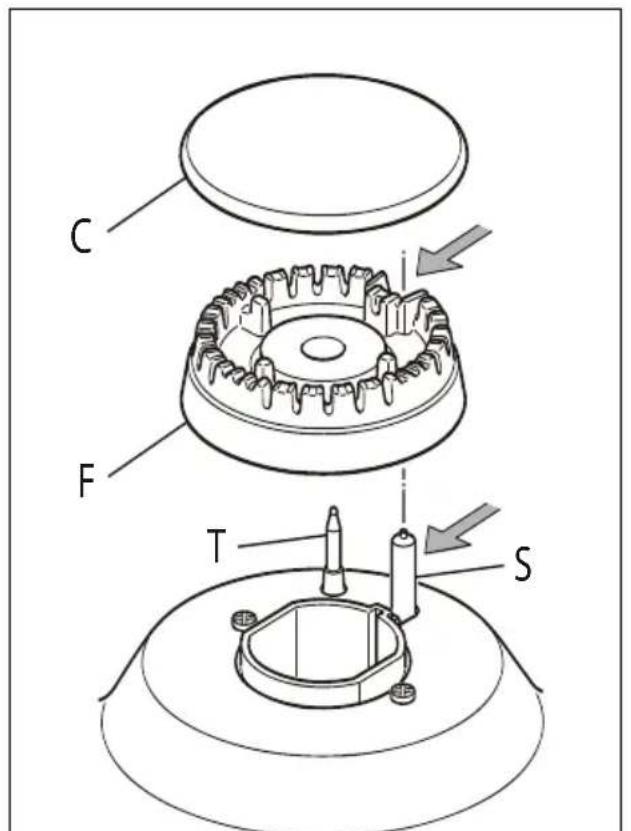
Check that the electrode "S" (figs. 6.1, 6.3) next to each burner is always clean to ensure trouble-free sparking.
Check that the probe "T" (figs. 6.1, 6.3) next to each burner is always clean to ensure correct operation of the safety valves.
Both the probe and ignition plug must be very carefully cleaned.
Note: To avoid damage to the electric ignition do not use it when the burners are not in place.
CORRECT REPLACEMENT OF THE AUXILIARY, SEMI-RAPID AND RAPID BURNERS
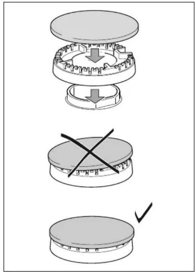
It is very important to check that the burner flame distributor "F" and the cap "C" has been correctly positioned (see figs. 6.1 - 6.2) - failure to do so can cause serious problems.
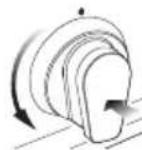
CORRECT POSITION OF THE DUAL BURNERS
The triple ring burner must be correctly positioned (see fig. 6.5); the burner rib must be enter in their logement as shown by the arrow (see fig. 6.3).
Then position the cap “A” and the ring “B” (figs. 6.4 - 6.5).
The burner correctly positioned must not rotate (fig. 6.5).
text_image
C F T SFig. 6.1 Fig. 6.2
text_image
Diagram illustrating three-step assembly process: top-down, cross-section, and final step with checkmark.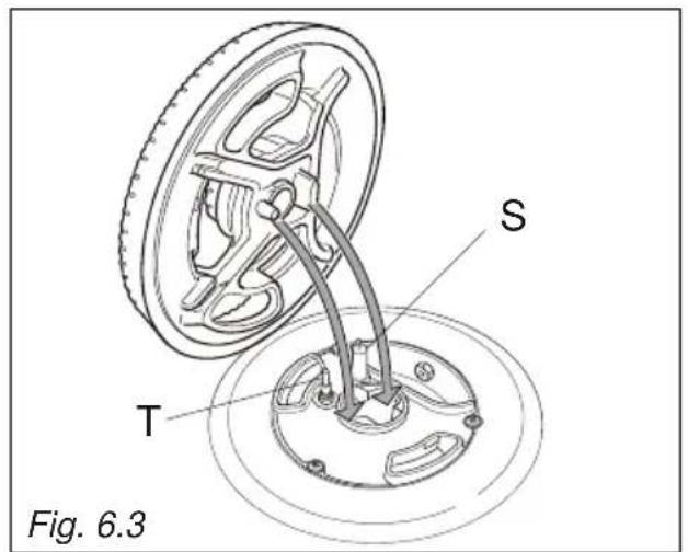
text_image
S T Fig. 6.3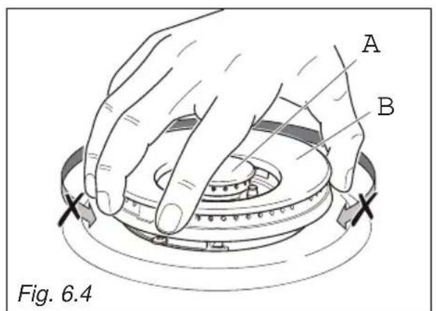
text_image
A B Fig. 6.4
natural_image
Three-step diagram showing a mechanical assembly with cross marks, no text or symbols presentOVEN FITTING OUT
- Assemble the wire racks to the oven walls using the 2 screws (fig. 6.7).
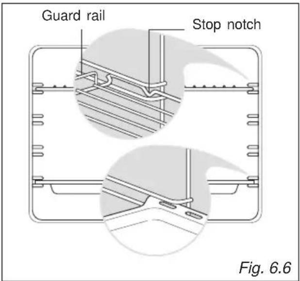
- Slide in, on the guides, the shelf and the tray (fig. 6.6).
The rack must be fitted so that the safety notch, which stops it sliding out, faces the inside of the oven; the guard rail shall be at the back.
- To dismantle, operate in reverse order.
text_image
Guard rail Stop notch Fig. 6.6
natural_image
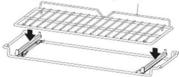
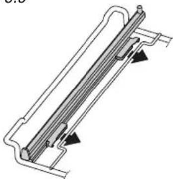
Technical line drawing of a mechanical component with a hand inserting a tool into a housing (no text or symbols)TELESCOPIC SLIDING SHELF SUPPORTS (fig. 6.8)
The telescopic sliding shelf support makes it safer and easier to insert and remove the oven shelf.
It stops when it is pulled out to the maximum position.
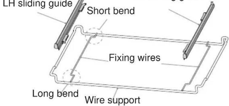
Important! When installing the sliding shelf support, make sure that:
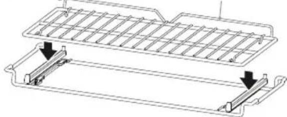
- You fit the RH and LH sliding guides on the wire support (fig. 6.9).
- You press the RH and LH sliding guides against the fixing wires (fig. 6.10). You will hear a click as the safety locks clip over the wire.
- You fit the oven shelf above the sliding shelf support (figs. 6.11, 6.8).
- You slide, on the guides inside the oven cavity, the sliding shelf support with the oven shelf fitted above:
– the oven shelf shall run out towards the oven door;
– do not use the top shelf position;
– the short bend on the wire support shall face the inside of the oven;
- the oven shelf must be fitted so that the guard rail faces the inside of the oven.
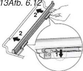
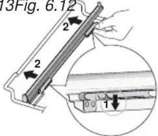
To remove the RH and LH sliding guides from the wire support:
• Find the safety locks. These are the tabs that clip over the fixing wire (arrow 1 in fig. 6.13).
• Pull the safety locks away from the fixing wire to release the sliding guide (arrow 2 in fig. 6.13).
Cleaning the sliding shelf supports:
- Wipe the supports with a damp cloth and a mild detergent only.
- Do not wash them in the dishwasher, immerse them in soapy water, or use oven cleaner on them.
Fig. 6.8 RH sliding guide
text_image
LH sliding guide Short bend Fixing wires Long bend Wire supportFig. 6.9
natural_image
Technical line drawing of a heat exchanger or cooling unit with no visible text or symbolsFig. 6.11 Fig. 6.10 Guard rail
natural_image
Technical line drawing of a mechanical component with two parallel plates and mounting brackets (no text or symbols)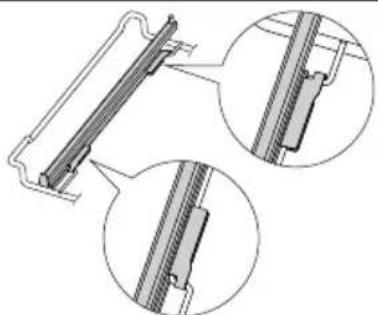
natural_image
Technical line drawing of a mechanical component with two circular inset views showing close-ups of internal structure (no text or symbols)
natural_image
Technical line drawing of a rectangular mechanical component with internal ribs and mounting holes (no text or symbols)Fig. 6.13 Fig. 6.12
text_image
13Fig. 6.12 2 2 1REPLACING THE OVEN LAMP
WARNING: Ensure the appliance is switched off and disconnected from the electrical power supply before replacing the lamp to avoid the possibility of electric shock.
- Let the oven cavity and the heating elements to cool down.
- Switch off the electrical supply.
- Remove the protective cover "A" (fig. 6.14).
- Replace the halogen lamp "B" with a new one suitable for high temperatures (300°C) having the following specifications: 220-240 V, 50/60Hz and same power (check watt power as stamped in the lamp itself) of the replaced lamp.
IMPORTANT WARNING: Never replace the bulb with bare hands; contamination from your fingers can cause premature failure. Always use a clean cloth or gloves.
- Refit the protective cover.
Note: Oven lamp replacement is not covered by your guarantee.

text_image
WRONG CORRECT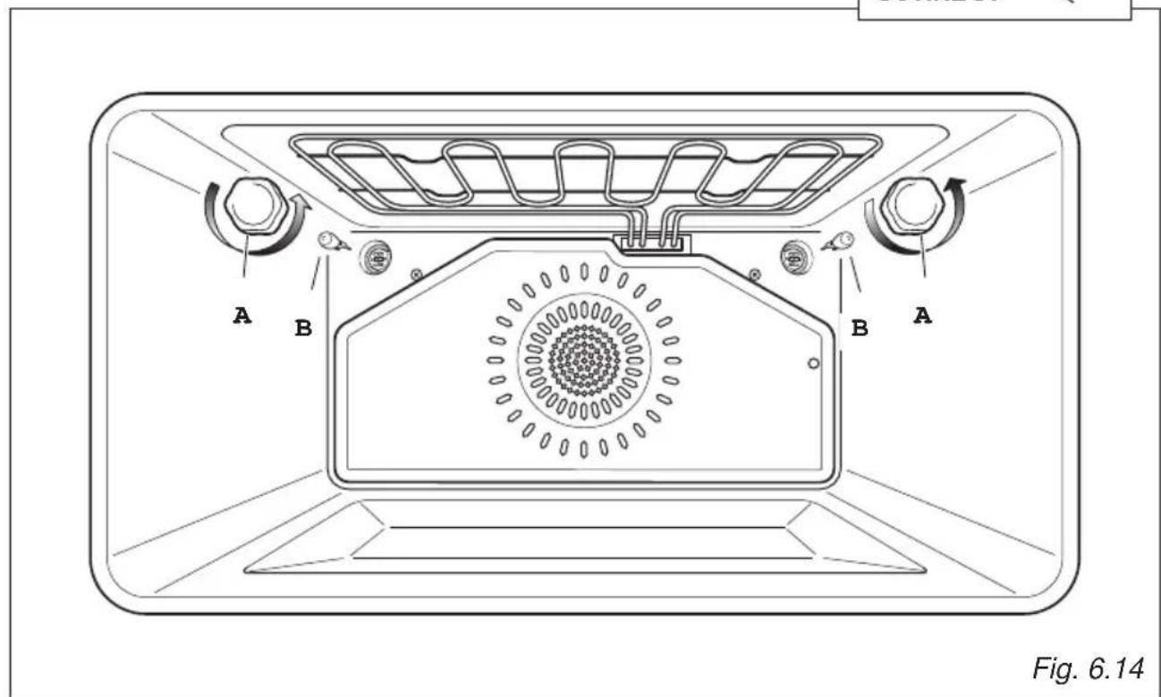
text_image
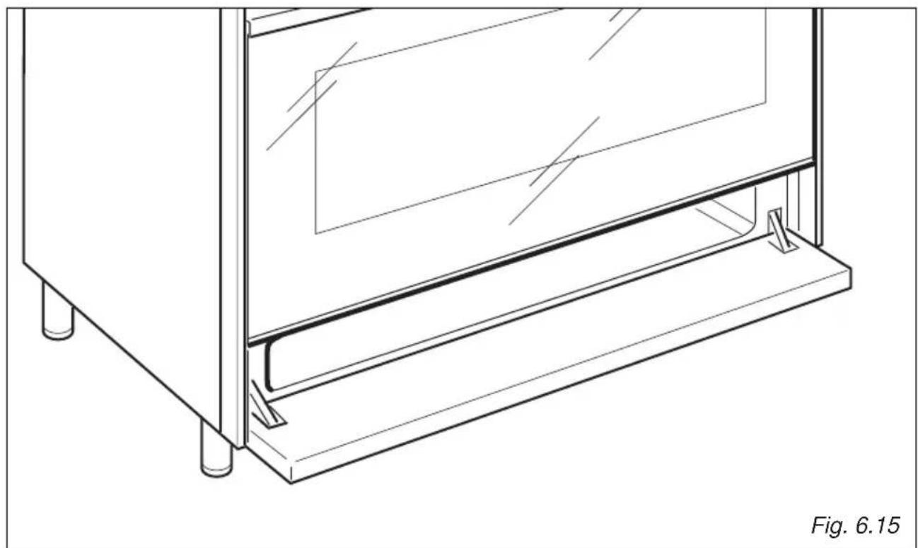
A B B A Fig. 6.14STORAGE COMPARTMENT
The storage compartment is accessible through the pivoting panel (fig. 6.15).
Do not store flammable material in the oven or in the storage compartment.
natural_image
Technical line drawing of a mechanical assembly with mounting feet and a transparent panel (no text or symbols)REMOVING AND REPLACING THE INNER DOOR GLASS PANE FOR CLEANING
If you wish to clean the inner glass of the door, make sure you follow the precautions and instructions very carefully.
Replacing the glass pane and the door incorrectly may result in damage to the appliance and may void your warranty.
IMPORTANT!
• Take care, the oven door is heavy. If you have any doubts, do not attempt to remove the door.
- Make sure the oven and all its parts have cooled down. Do not attempt to handle the parts of a hot oven.
• Take extreme care when handling the glass pane. Avoid the edges of the glass bumping against any surface. This may result in the glass shattering.
- CAUTION:
Do not use harsh abrasive cleaners or sharp metal scrapers to clean the oven door glass since they can scratch the surface, which may result in shattering of the glass.
- If you notice any sign of damage on any of the glass panes (such as chipping, or cracks), do not use the oven. Call your Authorised Service Centre or Customer Care.
- Make sure you replace the glass pane correctly. Do not use the oven without glass pane correctly in place.
- If the glass pane feels difficult to remove or replace, do not force it. Call your Authorised Repairer or Customer Care for help.
Note: service visits providing assistance with using or maintaining the oven are not covered by your warranty.

natural_image
Technical line drawing of a mechanical bracket assembly (no text or symbols)
text_image
A B Fig. 6.17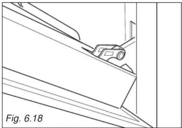
natural_image
Technical line drawing of a mechanical component on an inclined plane, labeled Fig. 6.18 (no text or symbols on the diagram itself)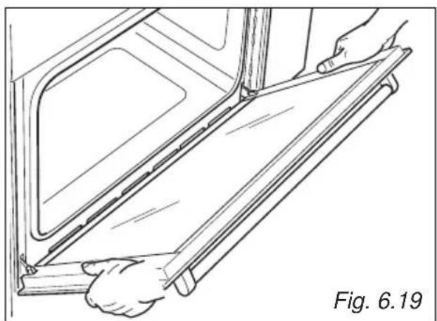
natural_image
Line drawing of a person installing or adjusting a door panel, labeled Fig. 6.19 (no text or symbols on the diagram itself)REMOVING THE OVEN DOOR
The oven door can easily be removed as follows:
- Open the door to the full extent (fig. 6.16).
- Open the lever "A" completely on the left and right hinges (fig. 6.17).
- Hold the door as shown in fig. 6.19.
- Gently close the door (fig. 6.18) until left and right hinge levers “A” are hooked to part “B” of the door (fig. 6.17).
- Withdraw the hinge hooks from their location following arrow "C" (fig. 6.20).
- Rest the door on a soft surface.
Important!
Always keep a safe distance from the door hinges, paying special attention to position
of your hands.
If the door hinges are not correctly hooked, they could unhook and close suddenly and unexpectedly with risk of injury.
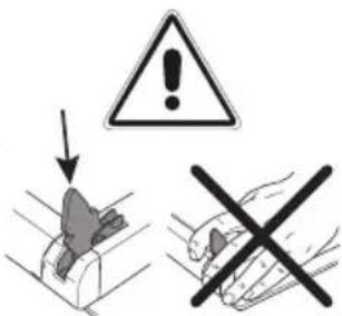
text_image
Warning sign with warning triangle and hand gesture, indicating incorrect safety or hazard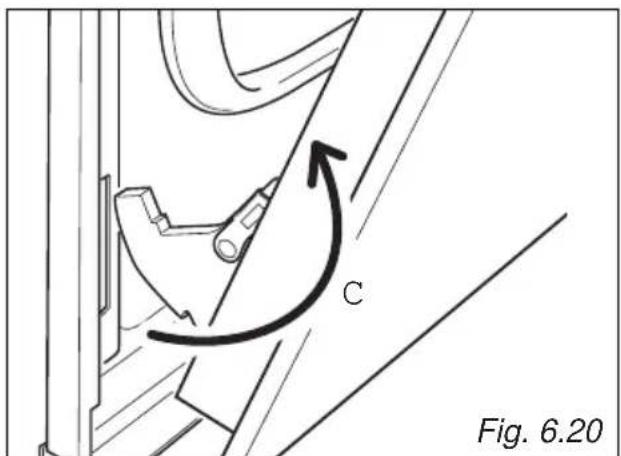
text_image
C Fig. 6.20REMOVING THE INNER PANE OF GLASS
The oven door is fitted with no. 2 panes:
- no. 1 outside;
- no. 1 inner.
To clean all panes on both sides it is necessary to remove the inner pane as follows:
REMOVE THE INNER GLASS RETAINER
- Remove the oven door and place it on a soft surface.
IMPORTANT: The door shall be placed horizontally as per fig. 6.21. - Press down on both tabs to release the glass retainer.
- Remove the glass retainer.
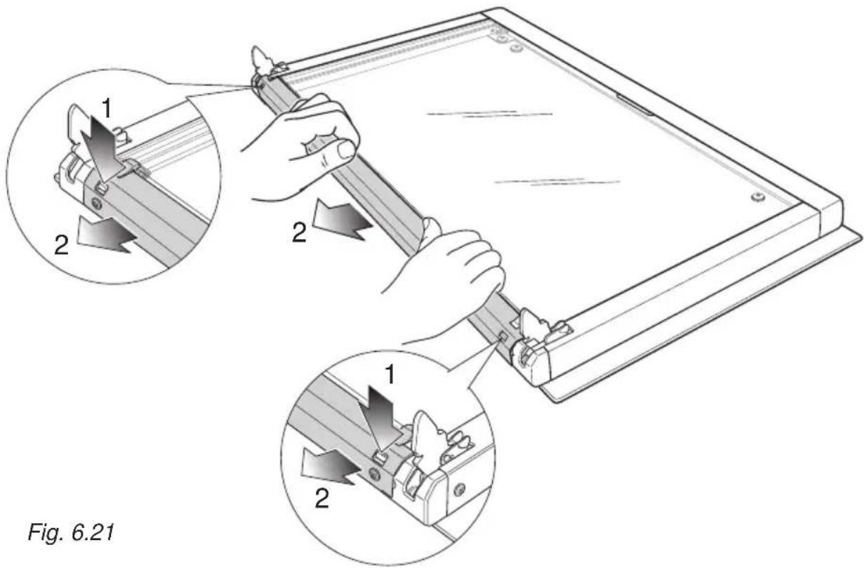
text_image
Fig. 6.21REMOVE THE INNER GLASS PANE
Lift and remove the inner pane slightly, as shown in the figure 6.22.
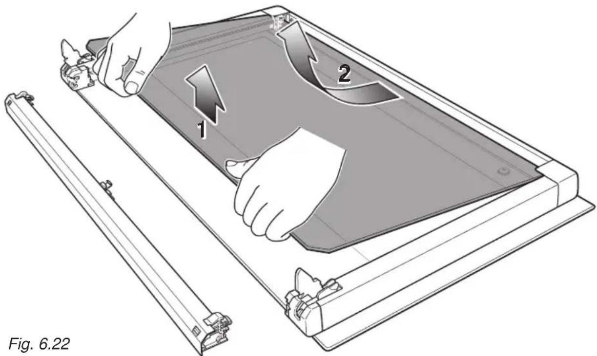
natural_image
Illustration of a device being handled with two hands, showing internal components and motion arrows (no text or symbols)AFTER CLEANING, REPLACE THE INNER GLASS PANE
When replacing the inner glass pane, make sure that:
- you replace the pane correctly, as shown. The pane must be in the position described below in order to fit into the door and to ensure that the appliance operates safely and correctly.
- you take extra care not to bump the edges of the glass against any object or surface.
- you do not force the pane into place. If you are experiencing difficulties replacing the pane, remove it and start the process again from the beginning. If this still does not help, call Customer Care.
- check that you are holding the pane the correct way. You should be able to read the wording on it as it faces you.
-
Check that the gasket "A" is in place (fig. 6.23). If not, correctly place the gasket in the top edge of the inner glass (in the centre).
-
Insert the inner glass pane in the uppermost pair of grooves and push it slightly (arrow 1 in figure 6.23).
-
Gently lower into place (arrow 2 in figure 6.23).

text_image
Fig. 6.23 1 2 AREPLACE THE GLASS RETAINER
- Position the glass retainer, as shown in the figure 6.24. It should sit on the bottom edge of the outer glass. Check that the clamps "M" are not deformed or damaged.
- Gently push the glass retainer back into place. You should be able to hear the tabs on both sides click as they lock the glass retainer in.
Important!
Make sure the glass retainer is correctly and firmly in place and that the glass pane is secure.
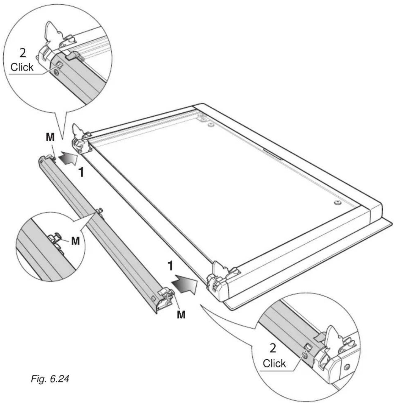
text_image
2 Click M 1 M 1 M 2 Click Fig. 6.24REFIT THE DOOR
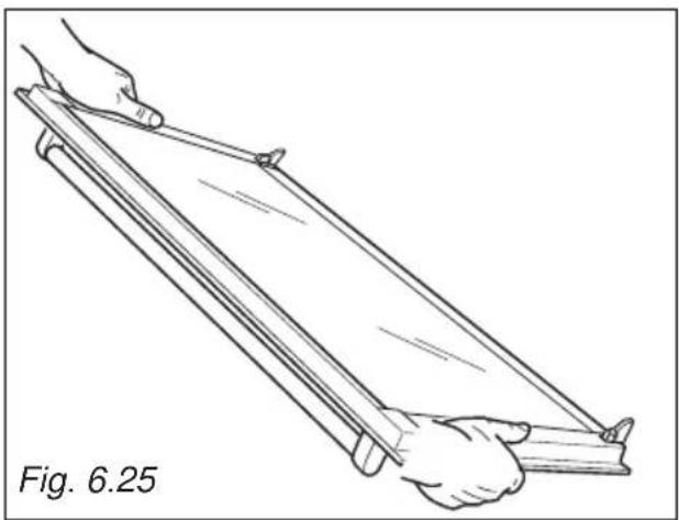
- Hold the door firmly (fig. 6.25).
- Insert the hinge tongues into the slots, making sure that the groove drops into place as shown in the figure 6.26.
- Open the door to its full extent.
- Fully close the levers "A" on the left and right hinges, as shown in the figure 6.27.
- Close the door and check that it is properly in place.
natural_image
Line drawing of two hands holding a wooden plank, labeled Fig. 6.25 (no text or symbols on the diagram itself)
natural_image
Technical diagram showing a mechanical component with an arrow indicating motion, labeled Fig. 6.26 (no text or symbols on the diagram itself)
text_image
A Fig. 6.27Advice for the Installer
IMPORTANT
- Cooker installation and regulation must only be carried out by QUALIFIED TECHNICIANS and in compliance with the local safety standards. Failure to observe this rule will invalidate the warranty.
- The appliance must be installed in compliance with regulations in force in your country and in observation of the manufacturer's instructions.
- The electrical mains outlet, if located behind the cooker, must not be higher than 18 cm above the floor level.
- Some appliances are supplied with a protective film on steel and aluminium parts. This film must be removed before using the cooker.
INSTALLATION
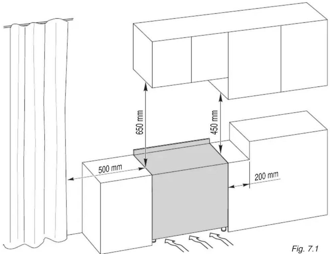
This cookers has class "2/1" overheating protection so that it can be installed in a cabinet.
The appliance must be kept no less than 200 mm away from any side wall which exceed the height of the hob surface (fig. 7.1).
The furniture walls adjacent to the cooker must be made of material resistant to heat.
The veneered syntetical material and the glue used must be resistant to a temperature of 90^ C in order to avoid ungluing or deformations.
The cooker may be located in a kitchen, a kitchen/diner or bed-sitting room but not in a room containing a bath or shower.
Curtains must not be fitted immediately behind appliance or within 500 mm of the sides.
It is essential that the cooker is positioned as stated below.
The cooker must be installed by a qualified technician and in compliance with a local safety standards.
text_image
650 mm 450 mm 500 mm 200 mm Fig. 7.1BACKGUARD
Before installing the cooker, assemble the backguard "C" (fig. 7.2).
- The backguard "C" can be found packed at the rear of the cooker.
- Before assembling remove any protective film/adhesive tape.
- Remove the two spacers "A" and the screw "B" from the rear of the cooktop.
- Assemble the backguard as shown in figure 7.2 and fix it by screwing the central screw "B" and the spacers "A".
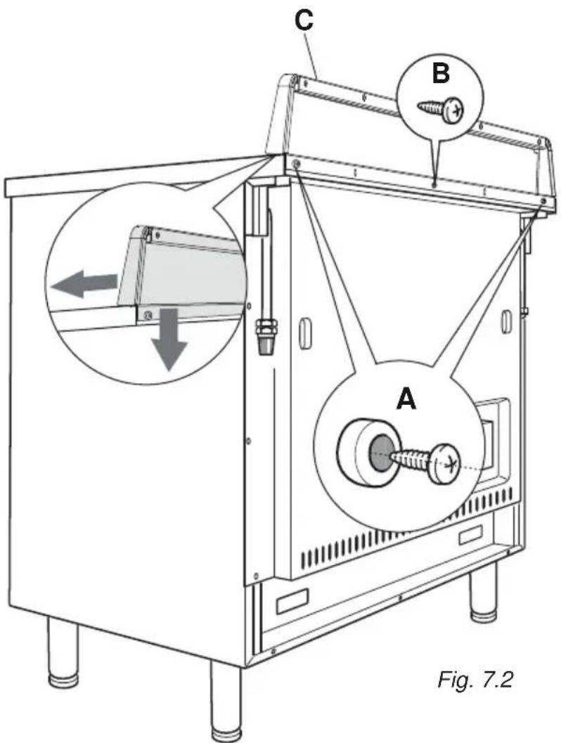
text_image
C B A Fig. 7.2FITTING THE ADJUSTABLE FEET
The adjustable feet must be fitted to the base of the cooker before use.
Rest the rear of the cooker an a piece of the polystyrene packaging exposing the base for the fitting of the feet.
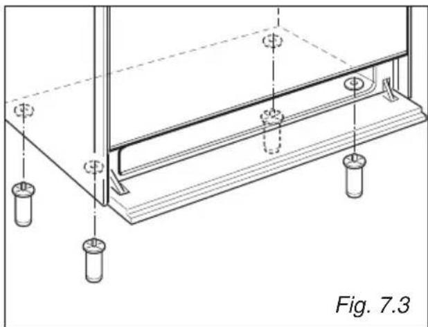
natural_image
Technical line drawing of a structural support frame with mounting holes and supports (no text or symbols)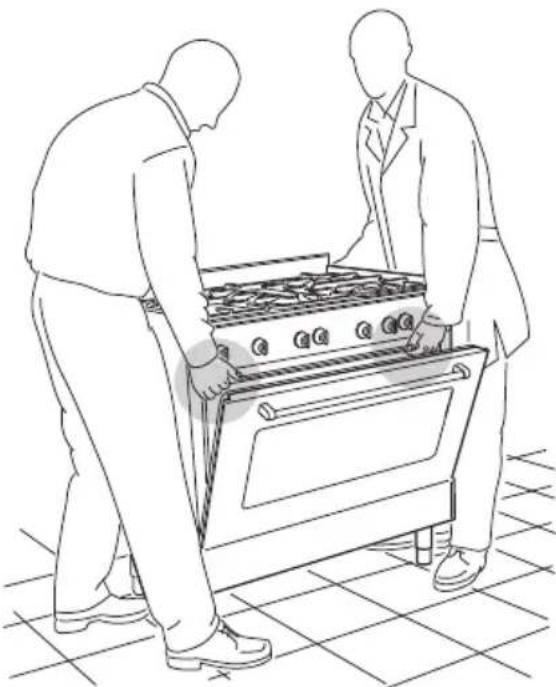
natural_image
Line drawing of two people installing or adjusting a large stove on a tiled floor (no text or symbols)Fig. 7.4
text_image
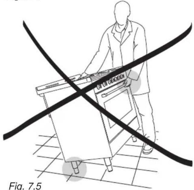
CCT CNT GENESIS Fig. 7.5Fig. 7.5
natural_image
Line drawing of a person using a portable stove with a diagonal line crossing the stove (no text or symbols)MOVING THE COOKER
WARNING
When raising cooker to upright position always ensure two people carry out this manoeuvre to prevent damage to the adjustable feet (fig. 7.4).
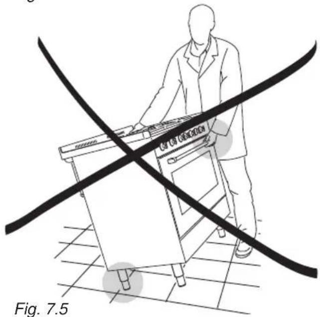
WARNING
Be careful: DO NOT LIFT the cooker by the door handle when raising to the upright position (fig. 7.5).
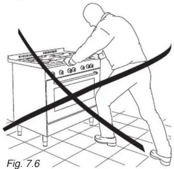
WARNING
When moving cooker to its final position DO NOT DRAG (fig. 7.6).
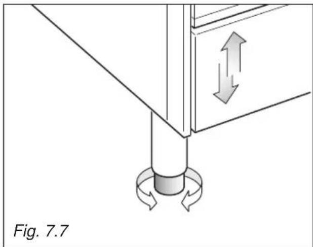
Lift feet clear of floor (fig. 7.4).
The cooker may be levelled by screwing the lower ends of the feet IN or OUT (fig. 7.7)
natural_image
Diagram of a mechanical assembly with directional arrows indicating movement, labeled Fig. 7.7 (no text or symbols on the diagram itself)ANTI-TILT BRACKET
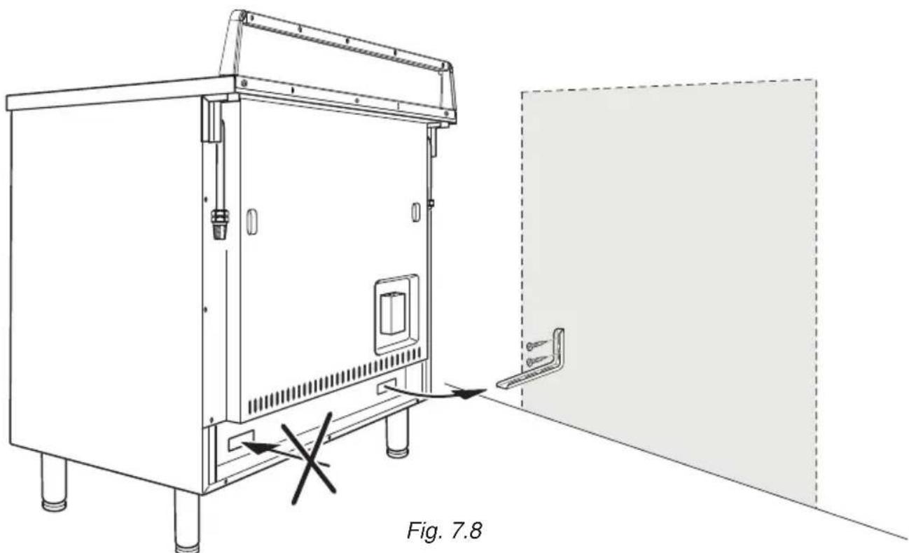
Warning: This appliance must be restrained to prevent accidental tipping by fitting a bracket to the rear of the appliance and securely fixing it to the wall.
To fit the anti-tilt bracket:
- After you have located where the cooker is to be positioned, mark on the wall the place where the 2 screws of the anti-tilt bracket have to be fitted. Please follow the indications given in fig. 7.8.
- Drill two 8 mm diameter holes in the wall and insert the plastic plugs supplied. Important! Before drilling the holes, check that you will not damage any pipes or electrical wires.
- Loosely attach the anti-tilt bracket with the 2 screws supplied.
- Move the cooker to the wall and adjust the height of the anti-tilt bracket so that it can engage in the slot on the cooker's back, as shown in fig. 7.8.
- Tighten the screws attaching the anti-tilt bracket.
- Push the cooker against the wall so that the anti-tilt bracket is fully inserted in the slot on the cooker's back.
Attention!
When sliding the cooker into place pay special attention not to trap the power supply cable in the stability bracket.
Pay special attention to the gas connection hose.
natural_image
Technical line drawing of a cabinet with an open door and a warning symbol, labeled Fig. 7.8 (no text or symbols on the diagram itself)VENTILATION REQUIREMENTS
The appliance must be installed in compliance with applicable local regulations concerning ventilation and the evacuation of exhaust gases.
Intensive and prolonged use may require extra ventilation, e.g. opening a window, or more efficient ventilation increasing the mechanical suction power if this is fitted.
The room where the gas appliance is to be installed must have a natural flow of air so that the gas can burn (in compliance with applicable local regulations).
The flow of air must come directly from one or more openings made in the outside walls with a free area of at least 100 cm^2 (or refer to applicable local regulations).
The openings should be near the floor and preferably on the side opposite the exhaust for combustion products and must be made so that they cannot be blocked from either the inside or the outside.
When these openings cannot be made, the necessary air can come from an adjacent room which is ventilated as required, as long as it is not a bed room or a danger area (in compliance with applicable local regulations).
In this case, the kitchen door must allow the passage of the air.
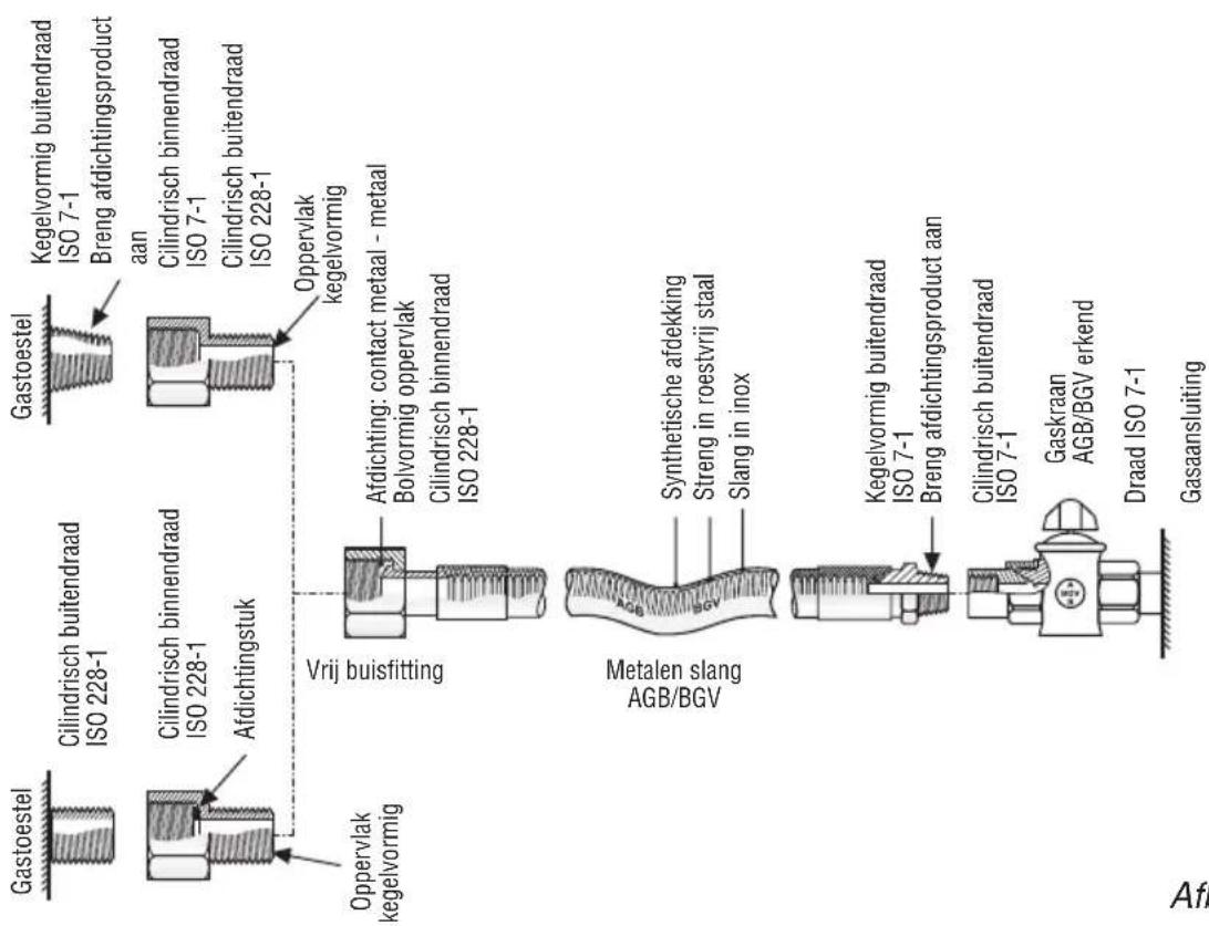
DISCHARGING PRODUCTS OF COMBUSTION
Extractor hoods connected directly to the outside must be provided, to allow the products of combustion of the gas appliance to be discharged (fig. 7.9).
If this is not possible, an electric fan may be used, attached to the external wall or the window; the fan should have a capacity to circulate air at an hourly rate of 3-5 times the total volume of the kitchen (fig. 7.10).
The fan can only be installed if the room has suitable vents to allow air to enter, as described under the heading “Choosing suitable surroundings”.
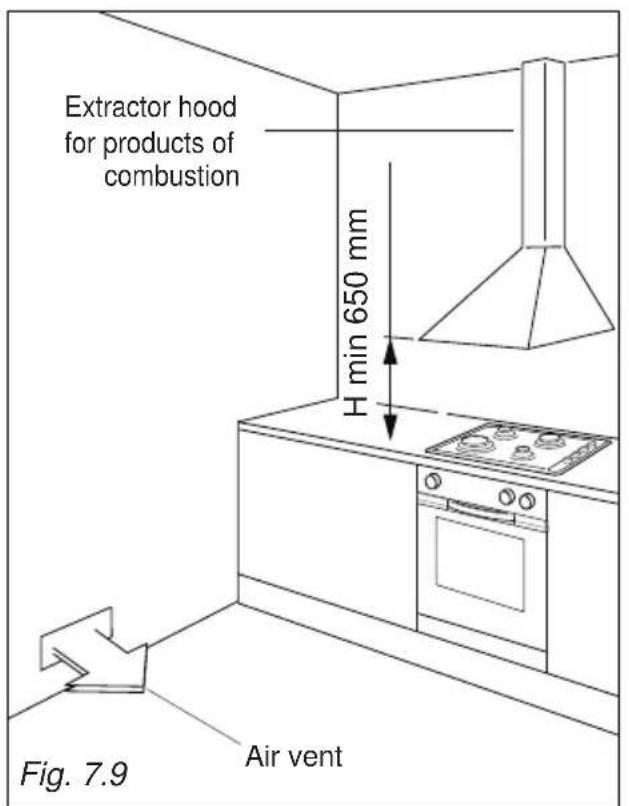
text_image
Extractor hood for products of combustion H min 650 mm Fig. 7.9 Air vent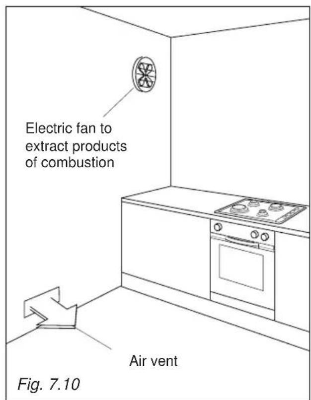
text_image
Electric fan to extract products of combustion Air vent Fig. 7.10The walls adjacent to the cooker must be of material resistant to heat.
GAS CONNECTION
The connection must be executed by a qualified technician according to the relevant standards.
The appliance is predisposed and calibrated to operate with the gas indicated on the specifications plate.
Ensure that the room in which the cooker is to be installed is adequately ventilated, in compliance with applicable regulations.
Connection to the gas supply pipe or gas cylinder must be made in accordance with the requirements of the applicable regulations.
The gas supply is connected at the rear of the cooker (fig. 8.1) to the R or L terminal of the gas inlet pipe; the connection pipe must not cross the rear of the appliance.
The terminal not used must be closed off with the plug T and gasket.
Before installation, make sure that the local distribution conditions (type of gas and its pressure) and the adjustment of this appliance are compatible. The appliance adjustment conditions are given on the plate or the label.
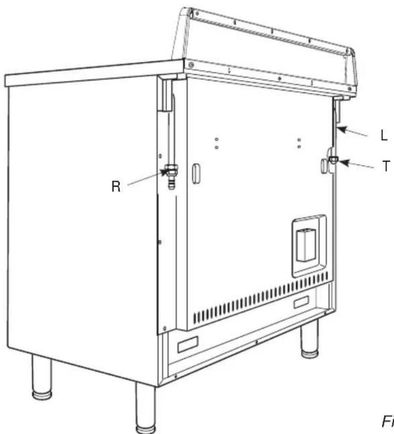
text_image
R L T FiFig. 8.1
A) GAS CONNECTION

Cat: II 2EK3B/P
The gases used for the operation of cooking appliances may be grouped by their characteristics into two types:
• G25.3 Natural gas
- G20 Natural gas
• G30 / G31 Butane/Propane
The fitting (fig. 8.2) is made up of:
A - Gas train terminal fitting (rh or lh)
B - Gasket
C - Conical connector
Use rigid or flexible connection pipes which comply with applicable regulations.
If compression fittings are used, tighten firmly using two spanners (fig. 8.4).
In particular, make sure that:
- the flexible hose does not come into contact with any parts of the cooker with surface temperatures in excess of 70^ ;
- the flexible hose does not exceed 75 cm in length and does not come into contact with sharp edges or corners;

text_image
NL A B C 1/2" gaz conique Fig. 8.2- the hose is not under tension or twisted and is not kinked or too tightly bent;
- the connection with rigid metal pipes should not cause stresses to the gas ramp.
- we advise replacing the gasket on the slightest sign of deformation or imperfection.
- the hose can easily be inspected along its entire length to check its condition; hoses should replaced after a maximum of three years.
- the cylinder cock or the supply cock immediately ahead of the appliance is closed whenever the cooker is not in use.
This appliance was configured for the appliance category K ( I_2K ) and is suitable for the use of G and G+ distribution gases according to the specifications as included in the NTA 8837:2012 Annex D with a Wobbe index of 43.46 – 45.3 MJ/m ^3 (dry, 0 °C, upper value) or 41.23 – 42.98 (dry, 15 °C, upper value).
This appliance can moreover be converted and/or again be calibrated for the appliance category E ( I_2E ).
This therefore implies that the appliance: “is suitable for G+ gas and H gas or is demonstrably suitable for G+ gas and can demonstrably be made suitable for H gas” within the meaning of the “Dutch Decree of 10 May 2016 regarding amendment of the Dutch Gas Appliances Decree...”.
B) CONNECTIONS TO THE GAS
SUPPLY FOR:

Cat: II 2E+3+
The gas connections are made on the left or on the right (fig. 8.1) at the rear of the appliance, in such a way that the pipe never passes behind the cooker.
The end of the gas connection, whether on the left or right, that is not being used, must be closed by attaching a cap fitted with a seal.
• Installation can only be carried out by a qualified technician, and must conform with the local regulations in force (NBN Standard D 51-003).
- The surfaces next to the cooker must either be made of a heat resistant material, or must be covered by such a material.
- Ventilation of the room - the combustion of gas can only occur because there is oxygen present in the air. The air must therefore be able to be renewed, and the products of combustion must be able to be expelled. The volume of renewed air must be at least 2m^3/h for each kW.
Gases normally used can be grouped into two main families:
- Liquid Gas: Butane Gas (G30); Propane Gas (G31)
- Natural Gas (G20/G25)
The cooker is supplied ready to operate, using the type of gas which is indicated on the label attached to it. Sometimes, however, it may be necessary to change from one gas to another.
Whatever type of gas the cooker is designed for, the following procedures must be followed:
- Connection to the gas supply.
- Replacement of the burners on the cooking surface.
- Adjustment of the gas flow to the burners on the cooking surface.
Ensure that the cooker is equipped for the type of gas it is to be supplied with (see label).
The gas supply circuit must conform to the local regulations in force.
The group of attachments (fig. 8.3) is made up of:
- 1 nut "A" (external cylindrical thread ISO 228-1)
- 1 sealing washer "D"
- 1 conical connection “B” (internal cylindrical thread ISO 228-1, external conical thread ISO 7-1)
- 1 Butane/Propane Gas connector "C".

text_image
BE A D B D CFig. 8.3
Cookers must be connected using R_HT materials downstream from the AGB/BGV certificated gas stop-cock, except for single unit cookers that are not built-in.
As a general rule, cookers are connected downstream from the gas stop-cock, by:
• copper pipes having an appropriate wall thickness, or;
- steel pipes, or;
- flexible R _HT metal pipes with AGB certification, fitted in such a way that they will not be crushed or pulled during use. Their bending radius must not be less than that specified by the manufacturer.
Exception for single unit cookers that are not built-in.
- These cookers must be connected by a flexible elastomer hose with a built-in undetachable mechanical nozzle. Only use those hoses that are authorised with the label "AGB/BGV".
-
Two types of flexible elastomer hoses: until April 2005, there were 2 types of flexible elastomer hoses on the market:
-
the old asymmetrical model, including an end with a fixed nozzle at the side of the cooker, and a nozzle with a loose nut and a built-in flat sealed joint at the side of the inside fitting (stop cock).
- the new symmetrical model, including a nozzle with a loose nut at both sides, with a built-in flat sealed joint. This symmetrical model is the only one that will be available after the time limit.
When installing a new cooker, or replacing an existing one, the symmetrical model must always be used.
Assembly
The gas inlet on the old cookers is equipped with a conical thread ISO 7-1 – and the hose is assembled as follows:
- apply a sealing product to the thread on the appliance: a strip of teflon or sealing paste for threads (colmat) plus some acrylic wool;
- tighten up the linking component (the cylindrical inside thread ISO 7-1 to the cylindrical ouside thread ISO 228-1) with the two keys on the cooker;
- check that the sealed joint is firmly inserted inside the moveable connection on the elastomer hose (new model);
- tighten up by hand the elastomer hose on both sides;
- tighten up with a spanner;
- open the stop cock and check that there are no leaks (soap bubbles) by smearing on a frothing product).
The gas inlet on the new appliances is equipped with a parallel thread ISO 228-1. To assemble it, follow stages 3, 4, 5, and 6 as described below.
Precautions to take:
- the flexible pipe must be mounted so that it will not be subjected to mechanical stresses, such as being twisted, compressed or pulled;
- the flexible pipe must be fitted so that it will not come into contact with any other movable piece of furniture;
- it must have a bending radius of at least ten times its outside diameter;
- it must not come into contact with any hot surfaces;
- ensure that it is installed in a place with easy access, so that its entire length can be checked.
- it should not be located in an overheated environment. and must be protected from sunlight and ultraviolet rays
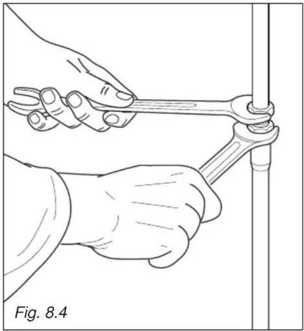
natural_image
Line drawing of hands using a wrench to lift a vertical pipe, labeled Fig. 8.4 (no text or symbols on the diagram itself)Periodical checks and replacement
The gas connection pipe must be checked at least annually to ensure that there is no visible deterioration. The hose must be replaced no later than the replacement date indicated.
IMPORTANT:
Take the precaution of using two keys when screwing up the components. (fig. 8.4).
After connecting the gas, use a soapy solution to check that the connections are sealed tight, and never use an open flame.
Flexible metal R_HT pipe, AGB-BGV certificated
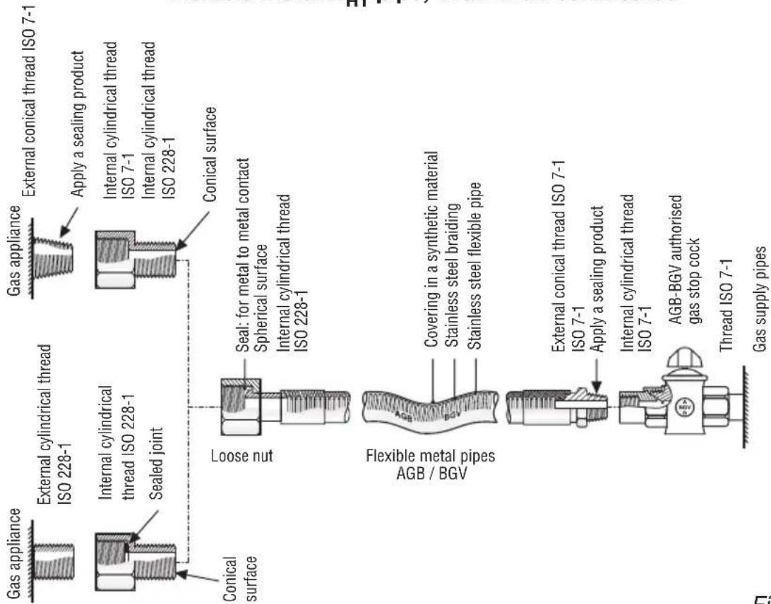
text_image
Gas appliance External cylindrical thread ISO 228-1 Internal cylindrical thread ISO 228-1 Sealed joint Conical surface Loose nut Seal: for metal to metal contact Spherical surface Internal cylindrical thread ISO 228-1 Flexible metal pipes AGB / BGV Covering in a synthetic material Stainless steel braiding Stainless steel flexible pipe External conical thread ISO 7-1 ISO 7-1 Apply a sealing product Internal cylindrical thread ISO 7-1 AGB-BGV authorised gas stop cock Thread ISO 7-1 Gas supply pipes Gas appliance External conical thread ISO 7-1 Apply a sealing product Internal cylindrical thread ISO 7-1 Internal cylindrical thread ISO 228-1 Conical surfaceFig. 8.5
A new flexible AGB-BGV elastomer hose in the two versions to be assembled.
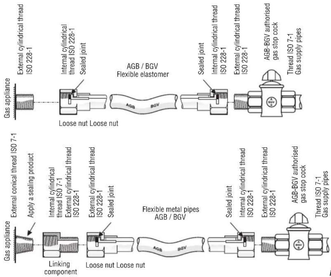
text_image
Gas appliance External conical thread ISO 7-1 Apply a sealing product Linking component Internal cylindrical thread ISO 7-1 External cylindrical thread ISO 228-1 Loose nut Loose nut Sealed joint AGB BGV Flexible metal pipes AGB / BGV Sealed joint Internal cylindrical thread ISO 228-1 External cylindrical thread ISO 228-1 AGB-BGV authorised gas stop cock Thread ISO 7-1 Gas supply pipes Gas appliance External cylindrical thread ISO 228-1 Internal cylindrical thread ISO 228-1 Sealed joint AGB / BGV Flexible elastomer Sealed joint Internal cylindrical thread ISO 228-1 External cylindrical thread ISO 228-1 AGB-BGV authorised gas stop cock Thread ISO 7-1 Gas supply pipesFig. 8.6
C) GAS CONNECTION

Cat: II 2E+3+
The fitting (fig. 8.7) is made up of:
A - Gas train terminal fitting (rh or lh)
G - Sealing gasket
For gases supplied by a pipe (natural gas, G20/G25), the connection can be made using one of the following:
• a rigid pipe with screw-nut;
• a metal corrugated flexible hose according to NF D 36-121 (fig. 8.8a);
- a flexible hose with mechanical ferrule according to NF D 36-103 or D 36-100 (fig. 8.8b);
For butane (G30) / propane (G31) distributed by cylinder or tank, the connection is made using one of the following:
• a rigid pipe with screw-nut;
• a metal corrugated flexible hose according to NF D 36-125 (fig. 8.8a);
- a flexible hose with mechanical ferrule according to NF D 36-112 (fig. 8.8b);
- Only for the appliances which cannot be built-in (classe 1) et only for butane-propane delivered in mobile containers: by fitting the proper hose holder (not supplied with the appliance), interposing a sealing gasket, and using a suitable flexible hose according to XP D 36-110 with an internal diameter of 6 mm (fig. 8.8c); make sure that the flexible hose is pushed over the hose connector to the full depth, and secured with a hose clamp (not supplied);
For Butane (G30)/Propane (G31) a gas pressure regulator, according to the Standard NF EN 13785, can be used as main gas shutoff valve to stop the gas supply when the appliance is not used.
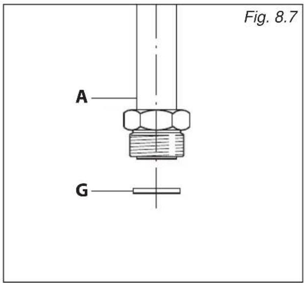
text_image
Fig. 8.7 A G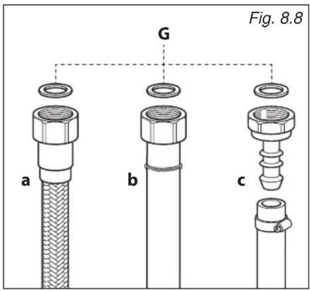
text_image
Fig. 8.8 a b c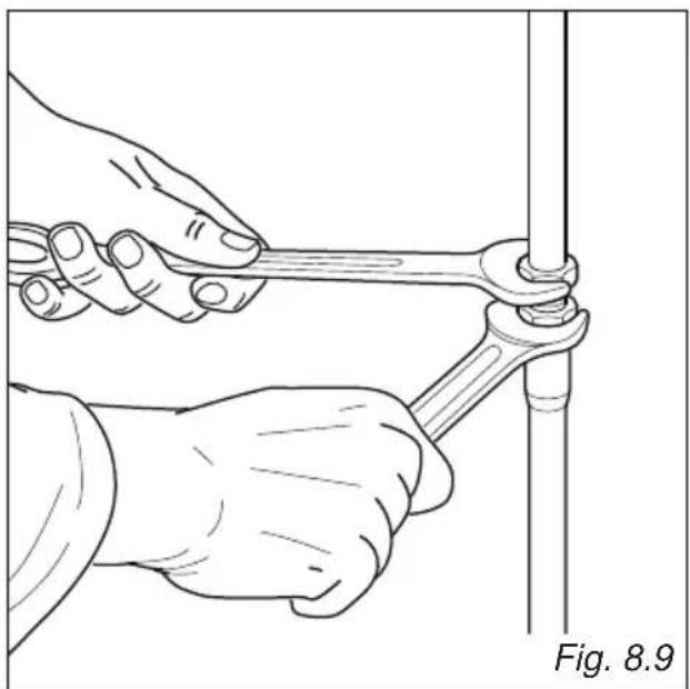
natural_image
Illustration of hands using a wrench to tie a pipe joint (no text or symbols)IMPORTANT:
- Note: In France, use a tube bearing the mark NF GAZ.
- Replace the sealing washer/s on the slightest sign of deformation or imperfection. The sealing washer/s is/are the part/s which guarantee/s a good seal in the gas connection.
• After connecting to the mains, check that the couplings are correctly sealed, using soapy solution, but never a naked flame.
- To fix the parts it is necessary to operate with 2 spanners (fig. 8.9).
- The connection with rigid metal pipes must not cause stress or pressure to the gas piping.
- The rigid or flexible pipes must conform with applicable local regulations. The flexible pipe shall be of the correct construction for the type of gas being used.
- Make sure the flexible pipe can easily be inspected along its entire length to check its condition; it must be replaced before the expiry date (marked on the pipe) or if it shows signs of wear or damage. Make sure the flexible pipe does not come into contact with sharp edges, corners or moving parts.
- Use a single flexible pipe only; never connect the appliance with more than one flexible pipe.
- Make sure the flexible pipe is not under tension, twisted, kinked or too tightly bent, neither while the appliance is in use nor while it is being connected or disconnected.
- Make sure the flexible pipe does not exceed 2000 mm in length or 750 mm for a rubber hose (or refer to applicable local regulations).
• If using a flexible pipe which is not entirely made of metal, make sure that it does not come into contact with any part of the appliance with a surface
temperature of 70^ C or above (or refer to applicable local regulations).
- When using a rubber hose for the gas connection, make sure it is as short as possible, without twists or kinks. To avoid any possible abrasion, make sure the hose does not come into contact with sharp edges, corners or moving parts.
- Make sure the hose is not subject to excessive heat by direct exposure to flue products or by contact with hot surfaces.
- The rigid or flexible pipe must be replaced if it shows signs of wear or damage.
- The rigid or flexible pipe must not be exposed to cleaning products (to avoid any possible corrosion).
- The customer must be informed that the gas shutoff valve ahead of the appliance should be closed when the product is not in use.
Gas maintenance
REPLACEMENT OF THE INJECTORS OF THE BURNERS
Select the injectors to be replaced according to the "Table for the choice of the injectors".
The nozzle diameters, expressed in hundredths of a millimetre, are marked on the body of each injector.
If the injectors are not supplied they can be obtained from the "Service Centre".
REPLACEMENT OF THE INJECTORS OF THE COOKTOP BURNERS
To replace the injectors proceed as follows:
- Remove pan supports and burners from the cooktop.
- Using a wrench, substitute the nozzle injectors "J" (figs. 8.10, 8.11) with those most suitable for the kind of gas for which it is to be used.
The burners are conceived in such a way so as not to require the regulation of the primary air.
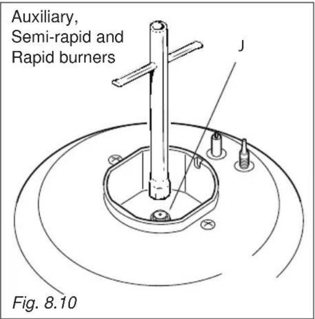
text_image
Auxiliary, Semi-rapid and Rapid burners Fig. 8.10Dual burner
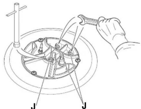
text_image
Technical diagram showing a hand operating a tool to lift a mechanical component, labeled with 'J' and a tool handle.Fig. 8.11
Injector for inner crown Injectors for outer crown
SETTING THE MINIMUM OF THE COOKTOP BURNERS
When switching from one type of gas to another, the minimum flow rate must also be correct: the flame should not go out even when passing suddenly from maximum to minimum flame.
To regulate the flame follow the instructions below:
Auxiliary, semi-rapid and rapid burners:
- Light the burner.
- Set the gas valve to the "minimum rate" position.
- Remove the knob.
- Using a screwdriver turn the screw "F1" until adjustment is correct (fig. 8.12).
Inside crown of DUAL burner:
• Light the DUAL burner.
- Set the gas valve to the "minimum rate" position of the inner crown only.
- Remove the knob.
- Using a screwdriver turn the screw "F3" until the correct setting is obtained (fig. 8.13).
Outside crowns of DUAL burner:
• Light the DUAL burner.
- Set the gas valve to the "minimum rate" position of the inner + outer crowns.
- Remove the knob.
- Using a screwdriver turn the screw "F2" until the correct setting is obtained (fig. 8.13).
For LPG gas, tighten the adjustment screws completely.
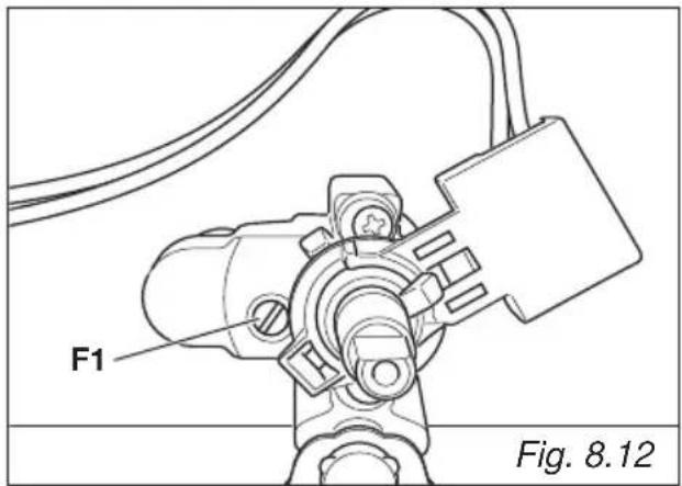
text_image
F1 Fig. 8.12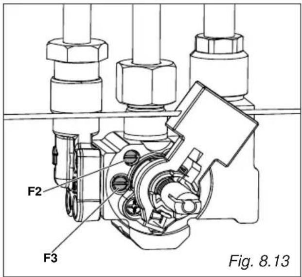
text_image
F2 F3 Fig. 8.13TABLE FOR THE CHOICE OF THE INJECTORS
- Cat: II 2EK3B/P
| G30/G3130/30 mbar | G2020 mbar | G25.325 mbar | ||||
| BURNERS | Nominal Power [Hs - kW] | Reduced Power [Hs - kW] | ∅ injector [1/100 mm] | ∅ injector [1/100 mm] | ∅ injector [1/100 mm] | |
| Auxiliary (A) 1,00 0,30 50 | 77 80 | |||||
| Semi-rapid (SR) 1,75 0,45 | 66 101 | 102 | ||||
| Rapid (R) | 3,00 0,75 | 87 129 | 132 | |||
| Dual (D) | inner crown | 0,80 (*) | 0,35 (*) | 46(no.1 central) | 70(no.1 central) | 71(no.1 central) |
| outer crowns | 4,00(**) | 1,90 (**) | 65(no.2 outer) | 99(no.2 outer) | 100 T2(no.2 outer) | |
(*) Power calculated with inner crown operating.
(**) Power calculated with inner and outer crowns operating.
FOR THE CHOICE OF THE INJECTORS
- Cat: II 2E+ 3+
| G30/G3128-30/37 mbar | G20/G2520/25 mbar | ||||
| BURNERS | Nominal Power [Hs - kW] | Reduced Power [Hs - kW] | ∅ injector[1/100 mm] | ∅ injector[1/100 mm] | |
| Auxiliary (A) | 1,00 | 0,30 | 50 | 77 | |
| Semi-rapid (SR) | 1,75 | 0,45 | 66 | 101 | |
| Rapid (R) | 3,00 | 0,75 | 87 | 129 | |
| Dual (D) | inner crown | 0,80 (*) | 0,35 (*) | 46 (no.1 central) | 70 (no.1 central) |
| outer crowns | 4,00(**) | 1,90 (**) | 65 (no.2 outer) | 99 (no.2 outer) | |
| AIR VENT NECESSARY FOR GAS COMBUSTION = (2 m3/h x kW) | ||
| BURNERS Air necessary for combustion [m 3/h] | ||
| Auxiliary (A) 2,00 | ||
| Semi-rapid (SR) 3,50 | ||
| Rapid (R) 6,00 | ||
| Dual (D) | inner crown 1,60 | |
| outer crown 8,00 | ||
LUBRICATION OF THE GAS TAPS
In case of difficulty in the gas taps operation, call Service.
IMPORTANT
All intervention regarding installation maintenance of the appliance must be fulfilled with original factory parts.
The manufacturer declines any liability resulting from the non-compliance of this obligation.
IMPORTANT: The cooker must be installed in accordance with the manufacturer's instructions.
Incorrect installation, for which the manufacturer accepts no responsibility, may cause injury to persons or animals etc.
GENERAL
- Connection to the mains must be carried out by qualified personnel in accordance with current regulations.
- The appliance must be connected to the mains checking that the voltage corresponds to the value given in the rating plate and that the electrical cable sections can withstand the load specified on the plate.
- The plug must be connected to an earthed socket in compliance with safety standards.
- The appliance can be connected directly to the mains placing an omnipolar switch with minimum opening between the contacts of 3 mm between the appliance and the mains.
- The power supply cable must not touch the hot parts and must be positioned so that it does not exceed 75°C at any point.
- Once the appliance has been installed, the switch or socket must always be accessible.
Before effecting any intervention on the electrical parts of the appliance, the connection to the network must be interrupted.
N.B. For connection to the mains, do not use adapters, reducers or brancing devices as they can cause overheating and burning.
If the installation requires alterations to the domestic electrical system or if the socket and appliance plug are incompatible, call an expert.
He should also check that the socket cable section is suitable for the power absorbed by the appliance.
IMPORTANT: this cooker must be connected to a suitable double pole control unit adjacent to the cooker.
WARNING!
This appliance must be earthed.
The connection of the appliance to earth is mandatory.
The manufacturer declines all responsibility for any inconvenience resulting from the none observance of this condition.
CONNECTION OF THE POWER SUPPLY CABLE
WARNING: If the power supply cable is damaged, it must be replaced only by an authorised service agent in order to avoid a hazard.
- Unhook the terminal board cover by inserting a screwdriver into the two hooks "A" (fig. 9.1).
- Open the cable gland by unscrewing screw "F" (fig. 9.2), unscrew the terminal screws.
- Insert the feeder cable of the suitable section (as described in the next chapter) into the cable gland.
- Connect the phase and earth cables to the terminal block according to the diagram in figure 9.3.
- Pull the feeder cable and block it with cable gland.
- Close the terminal block cover (check the two hooks "A" are correctly hooked).
IMPORTANT: To connect the power supply cable DO NOT unscrew the screws fixing the cover plate behind the terminal block.
N.B. The earth conductor must be left about 3 cm longer than the others.
FEEDER CABLE SECTION Type "H05RR-F"
220-240 V ac 3 x 1,5 mm ^2 (*)
(*) - Connection possible with plug and outlet
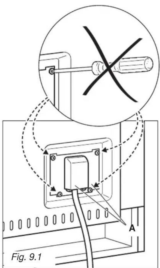
text_image
Fig. 9.1 A
natural_image
Technical line drawing of a mechanical component with labeled parts F and Fig. 9.2 (no text or symbols beyond labels)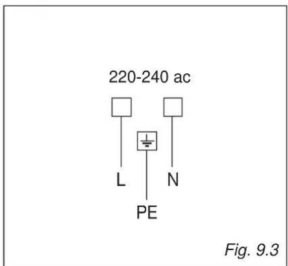
text_image
220-240 ac L PE N Fig. 9.3
text_image
BORETTIPassione in Cucina