QO 6009 PT X - Oven Fulgor Milano - Free user manual and instructions
Find the device manual for free QO 6009 PT X Fulgor Milano in PDF.

User questions about QO 6009 PT X Fulgor Milano
0 question about this device. Answer the ones you know or ask your own.
Ask a new question about this device
Download the instructions for your Oven in PDF format for free! Find your manual QO 6009 PT X - Fulgor Milano and take your electronic device back in hand. On this page are published all the documents necessary for the use of your device. QO 6009 PT X by Fulgor Milano.
USER MANUAL QO 6009 PT X Fulgor Milano
natural_image
Technical line drawing of a rectangular appliance with a circular vent and internal grating (no text or symbols)IMPORTANTE
natural_image
Technical line drawing of a refrigerator interior showing structural components and mounting brackets (no text or symbols)Importante:
natural_image
Interior view of a refrigerator with visible grilles and metal grilles (no text or symbols)PANNELLI AUTOPULENTI
natural_image
Simple line drawing of a five chasing arrow symbol (no text or labels)
natural_image
Diagram of a server room interior with airflow arrows indicating movement or ventilation (no text or symbols)Cottura ventilato


natural_image
Technical line drawing of a dual-chamber air vent or fan assembly (no text or symbols)Cottura al grill


natural_image
Cross-sectional diagram of a room with airflow and ventilation system (no text or labels)RAFFREDDAMENTO TANGENZIALE
text_image
12:35 Stop - + A B C D E F G H I J K L M N O P Q R S T U V W X Y Znatural_image
Diagram of a mechanical component with a rotating arrow indicating rotational motion (no text or symbols)1
natural_image
Line drawings showing a hand adjusting a door frame with a black arrow indicating the handle (no text or symbols present)text_image
Technical diagram of an electrical switch mechanism with labeled components and a magnified inset showing internal structure.
SERVIZIO ASSISTENZA TECNICA: 199.151.195
Dear Customer,
we would like to thank you and congratulate you on your choice.
This new product has been carefully designed and built using top quality materials, and meticulously tested to ensure that it meets all your culinary requirements.
Please read and observe these simple instructions, which will enable you to achieve excellent results from the very first time you use it. This state-of-the-art appliance comes to you with our very best wishes.
THE MANUFACTURER
I Italiano
GB English
FR Français
DE Deutsch
ES Español
PT Português
THIS PRODUCT IS DESIGNED FOR DOMESTIC USE.
THE MANUFACTURER DECLINES ALL RESPONSIBILITY FOR DAMAGES TO THINGS OR PEOPLE DERIVING FROM INCORRECT INSTALLATION OR IMPROPER, ERRONEOUS OR UNSUITABLE USE.
THE APPLIANCE MUST NOT BE USED BY PEOPLE (INCLUDING CHILDREN) WITH PHYSICAL, SENSORIAL OR MENTAL IMPAIRMENTS, OR BY PEOPLE WITHOUT THE NECESSARY EXPERIENCE OR KNOWLEDGE, UNLESS THEY ARE SUPERVISED OR INSTRUCTED IN THE USE OF THE APPLIANCE
BY A PERSON RESPONSIBLE FOR THEIR SAFETY.
CHILDREN MUST BE SUPERVISED TO ENSURE THAT THEY DO NOT PLAY WITH THE APPLIANCE.
DO NOT PLACE TIN FOIL, PANS OR SIMILAR IN CONTACT WITH THE INNER BASE OF THE OVEN TO COOK. THE HEATING ACTION OF THE LOWER RESISTANCE CAUSES THE LOWER PART OF THE OVEN TO OVERHEAT, LEADING TO DAMAGE AND EVEN SERIOUS CONSEQUENCES (FIRE RISK) ALSO TO THE UNIT IN WHICH THE OVEN IS INSTALLED.
Contents
User instructions, 15
First use, 15
Self-cleaning panel, 15
Respect for the environment, 15
Control panel, 16
Instructions for use:
- conventional cooking, 16
- fan cooking, 16
- grill cooking, 17
Thermostat, 17
Electronic timer, 17
Setting the clock, 18
Setting the clock, 18
Minute counter, 18
Cooking time, 18
End of cooking time, 18
Programming automatic cooking, 19
Adjusting beep volume, 19
Light replacement, 19
Removing the oven door, 20
Installation instructions, 21
Flush fitting, 21
Electrical connections, 22
natural_image
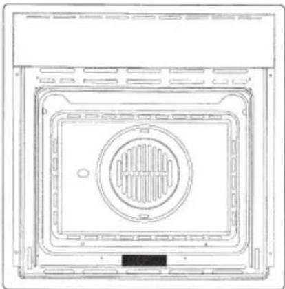
Technical line drawing of a rectangular appliance with a circular vent and internal grating (no text or symbols)IMPORTANT
The oven's data plate is accessible even with the oven fully installed. The plate is visible simply by opening the door. Always quote the details from it to identify the appliance when ordering spare parts.
User instructions
The first time you use the oven
Clean the oven thoroughly with soapy water and rinse well. To remove the lateral frames from smooth-walled ovens, proceed as shown in the figure.
Operate the oven for about 30 minutes at maximum temperature to burn off all traces of grease which might otherwise create unpleasant smells when cooking.
natural_image
Technical line drawing of a refrigerator interior showing internal components and mounting brackets (no text or symbols)Important:
As a safety precaution, before cleaning the oven, always disconnect the plug from the power socket or the power cable from the oven. Do not use acid or alkaline substances to clean the oven (lemon juice, vinegar, salt, tomatoes etc.). Do not use chlorine based products, acids or abrasive products to clean the painted surfaces of the oven.
DO NOT USE STEAM CLEANERS
Self-cleaning catalytic panels
natural_image
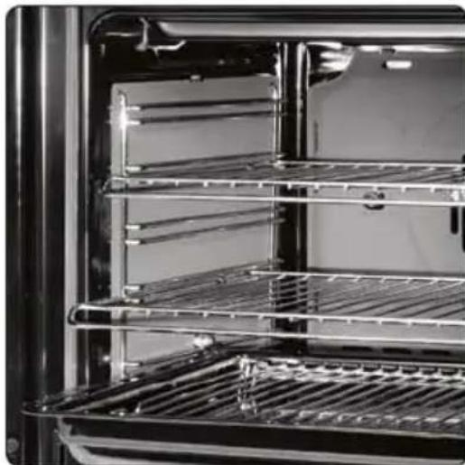
Interior view of an oven with metal grilles and a rack, showing no visible text or symbols.SELF-CLEANING PANELS
The CLEAN function activates the reaction that causes cleaning
Our smooth walled ovens can be fitted with selfcleaning panels to cover the inside walls.
These special panels are simply hooked on to the walls before the side frames are fitted. They are coated in a special, micro-porous catalytic enamel which oxidises and gradually vaporises splashes of grease and oil at cooking temperatures above 200°C.
If the oven is not clean after cooking fatty foods, operate the empty oven for 60 minutes (max.) at maximum temperature.
Never wash or clean selfcleaning panels with abrasive, acid, or alkaline products.
Respect for the environment
natural_image
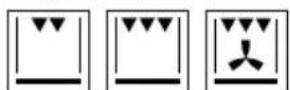
Abstract recycling symbol composed of five curved arrows forming a circle (no text or labels)Control panel functions
Function symbols on the selector
GB

Oven light (stays on while oven is in use).

Top and bottom heating elements. Thermostat setting from 50°C to MAX.

Top heating element (small, low power grill). Thermostat setting from 50°C to 200°C.

Bottom heating element. Thermostat setting from 50°C to MAX.

Top heating element (small, low)

Double top heating element (large area grill). Thermostat setting from 50°C to 200°C.

Double top heating element with fan (large area grill). Thermostat setting from 50°C to 200°C.

Top and bottom heating elements with fan. Thermostat setting from 50°C to MAX.

Circular heating element with fan. Thermostat setting from 50°C to MAX.

Bottom heating element + Circular heating element with fan. Thermostat setting from 50°C to MAX.

Fan for defrosting. Thermostat setting at 0°C.

Double top heating element (large area grill). Thermostat setting from 50°C to 200°C. Bottom heating element. Thermostat setting from 50°C to MAX.
Instructions for use
Conventional cooking


Conventional cooking uses top and bottom heat to cook a single dish.
Place the food in the oven only once cooking temperature has been reached, i.e. when the heating indicator goes out.
If you want to increase top or bottom temperature towards the end of the cooking cycle, set the temperature control to the right position. It is advisable to open the oven door as little as possible during cooking.
natural_image
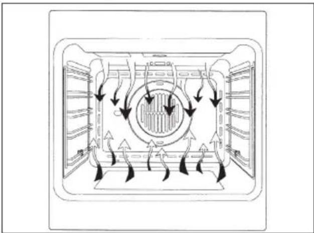
Diagram of airflow or heat transfer through a rectangular chamber with circular vent and fan-like structures (no text or symbols)Fan cooking


For this type of cooking a fan positioned at the back allows the circulation of hot air inside the oven, creating uniform heat. In this way cooking is more rapid than conventional cooking. It is a suitable method for cooking dishes on more than one shelf, especially when the food is of different types (fish, meat etc.).
Defrosting

By selecting one of the fan cooking functions and setting the thermostat to zero, the fan allows cold air to circulate inside the oven. In this way frozen food can be rapidly defrosted.
It is not essential to preheat the oven, but you are advised to do so when cooking pastries.
natural_image
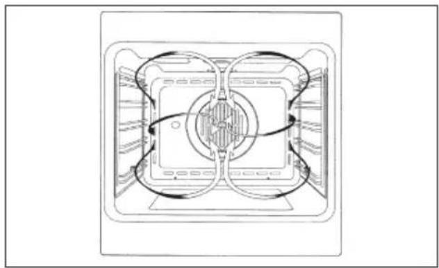
Technical line drawing of a dual-chamber air vent or fan assembly (no text or symbols)Grill cooking


Use the grill to grill or brown foods. Some ovens may be equipped with an electric motor, spit and skewers for turning on the spit.
Place the shelf with the food to be cooked in the 1st or 2nd position from the top.
Pre-heat the oven for 5 minutes. Turn the thermostat to a temperature between 50° and 200.
Cooling fan
natural_image
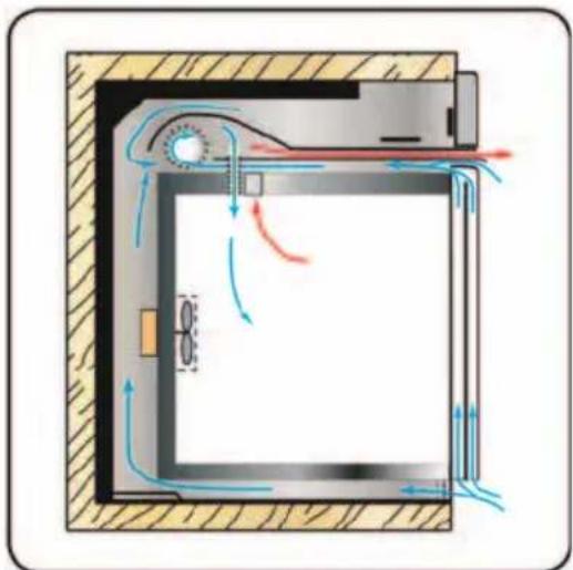
Cross-sectional diagram of a door with airflow indicators and ventilation system (no text or labels)TANGENTIAL COOLING
A forced air circulation system which contributes to reducing the heat exchange temperature in the front and lateral areas of the ovens.
The fan is positioned on the upper part of the oven and create a circle of cooling air on the inside of the furniture and through the door of the oven. It is turned on when the temperature of the outer shell of the oven reaches 60^ C.
By switching on the oven with the thermostat at 200°C
the fan starts working after approx.10 min.
It is turned off when the temperature of the outer shell of the oven descends under 60°C.
By switching off the oven with the thermostat at 200^ C the fan stops working after approx. 30 min.
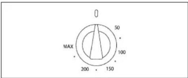
Thermostat
Use the thermostat to set the cooking temperature you need. The thermostat can be adjusted from 50° to 250°C.
text_image
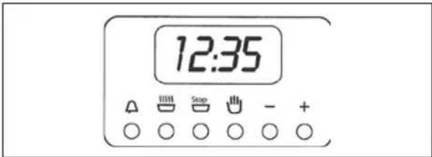
0 50 MAX 100 200 1506 Key electronic timer
Setting the clock
Press the duration □ key and the end of cooking □ key simultaneously, then press the +/- keys to set the time.
text_image
12:35 Stop - + A O O O O OManual operation
To start cooking without setting end of cooking time, press the manual key 🎨
Setting only the duration of cooking in semi-automatic mode
To set the duration of cooking, press the duration key and press the +/- keys to set the duration of cooking. A buzzer sounds when the cooking period finishes, and the oven switches itself off. Turn the thermostat and selector knobs back to 0 position and press the manual key.
Setting only the end of cooking time in semi-automatic mode
To set the end of cooking time, press the end of cooking key and press the +/- keys to set the time at which you want the oven to switch off. A buzzer sounds when the clock reaches the set time, and the oven switches

itself off. Turn the thermostat and selector knobs back to 0 position and press the manual key.
Fully automatic operation
To set the end of cooking time, press the duration key and press the +/- keys to set the duration of cooking. Press the end of cooking key and press the +/- keys to set the time at which you want the oven to switch off.
When you finish setting these times, the AUTO symbol flashes and the buzzer sounds. Press any key to silence it.
Alarm timer
Press the alarm timer key and press the +/- keys to set the required duration of cooking. The buzzer sounds when the cooking time ends. Press any key to silence it.
Programming errors
You cannot program in a cooking period which starts earlier than the time displayed on the clock. If you try to do so, the buzzer sounds and the AUTO symbol flasher. Simply change the duration or cooking time to correct the error.
Cancelling a cooking programme
To cancel a cooking programme, simply press the manual key.
Timer touch control
Setting the clock
text_image
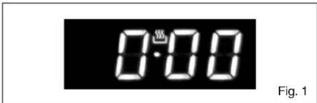
0:00 Fig. 1"Auto" and "0:00" will start flashing when the unit is switched on for the first time. To set the clock, press the central button for about 3 seconds. When 📋 appears, press "+" or "-" to set the correct time.
Wait until a beep tells you that the clock has been set (figure 1).
To set the time at a later stage, press "+" and "-" together for 3 seconds and then adjust the clock as described above.
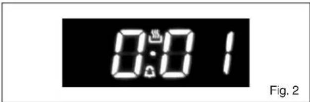
Minute counter
text_image
0:01 Fig. 2As this minute counter does not control the oven, when it finishes counting the oven will continue to work.
To set, press the central button for 3 seconds until appears (figure 2). Press "+" and "-" to set the required time.
To set the minute counter at a later stage, press the central button for 3 seconds and adjust as described above.
The minute counter beeps when it finishes counting. To disable it, press any button.
Cooking time
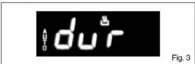
text_image
du^T Fig. 3This is a semi-automatic cooking function. It can be used to set cooking times.
Press the central button for 3 seconds. Then press it again until "dur" appears (figure 3). Press "+" and "-" to set the required cooking time.
End of cooking time
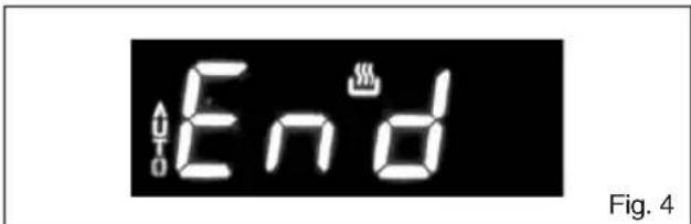
text_image
Auto End Fig. 4The end of cooking time can also be set.
Press the central button for 3 seconds. Press the central button twice consecutively and wait for "End" to appear (figure 4). Press "+" and "-" to set the required end of cooking time.
The oven will work in the set mode and at the set temperature until the end of cooking time.
Programming automatic cooking

text_image
AUTO du'r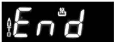
text_image
Auto EndFig. 5
Cooking function with set times.
Press the central button for 3 seconds. Then press it again until "dur" appears. Press "+" and "-" to set the required cooking time. Wait a few seconds for the setting to be memorised.
Press the central button for 3 seconds. Press it another two times and wait for "End" to appear (figure 4). Press "+" and "-" to set the required end of cooking time.
E.g.:
Current time: 12.30
Cooking time: 10 minutes
End of cooking time: 14.00
The oven will start cooking at 13.50 (14.00 less 00.10) at the set temperature and in the set mode and will stop at 14.00.
The oven will beep when it stops cooking. To disable it, press any button.
Adjusting beep volume
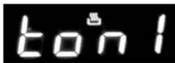
text_image
bon 1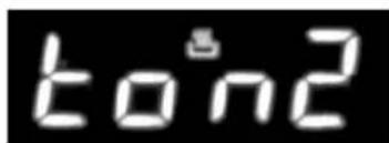
text_image
ton2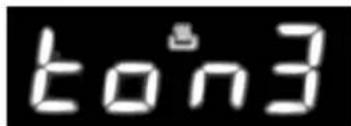
text_image
ton3Fig. 6
To adjust beep volume, press "+" and "-" together. Then press the central button and wait for "ton1" (high volume) to flash. Press "-" to select "ton2" (medium volume) or "ton3" (low volume).
Press the central button to set the selected volume.
Replacing the oven light
IMPORTANT:
The oven light must have these precise features: a) it must be able to resist high temperatures (up to 300°C)
b) power supply: see V/Hz indicated on data plate. c) power 25W.
d) E 14 connection. Before proceeding, disconnect the appliance from the main electricity supply.
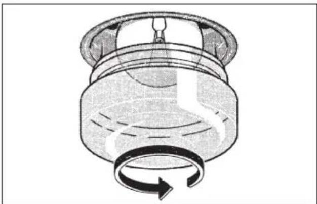
- To prevent damage, place a tea cloth in the oven;
- unscrew the glass cover of the light;
- unscrew the old light bulb and replace it with the new one;
- put back the glass cover and remove the tea cloth;
- connect the appliance to the main electricity supply;
natural_image
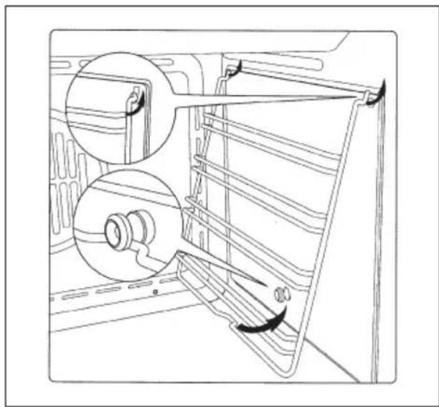
Diagram of a mechanical component with a rotating arrow indicating rotational motion (no text or symbols)Removing the oven door
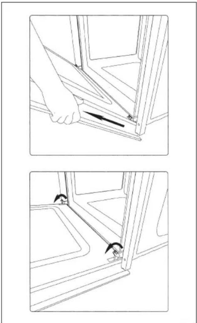
The oven door can be removed quickly and easily. To do so, proceed as follows:
GB
- Open the door fully.
- Lift the two levers shown in fig.
- Close the door as far as the first stop (caused by the raised levers).
- Lift the door upwards and outwards to remove it from its mountings.
To replace fit the door, fit the hinges in their mountings and lower the two levers.
natural_image
Technical line drawing showing two steps of a hand holding a bracket, with arrows indicating movement direction (no text or symbols present)Installation instructions
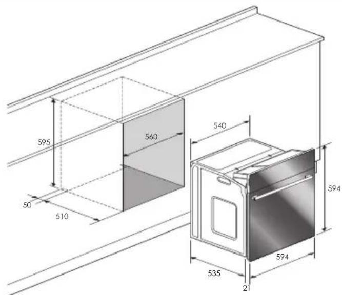
Flush fitting
The oven can be installed under a work top or in a cooking column. Figure shows the installation dimensions.
Make sure that surrounding materials are heat resistant. Align the oven centrally with respect to the side walls of the units surrounding it and fix it in place with the screws and Allen screws provided.
See the accompanying instructions for combining the oven with multi-functional gas or gas-electric cookers.
GB
text_image
595 560 540 50 510 594 535 21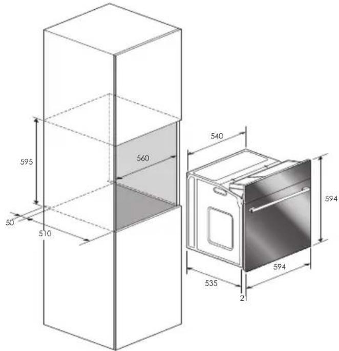
text_image
595 50 510 560 540 535 21 594 594Electrical connections
Before connecting the oven to the mains power supply, make sure that:
- The supply voltage corresponds to the specifications on the data plate on the front of the oven.
- The mains supply has an efficient earth (ground) connection complying with all applicable laws and regulations. Correct earthing (grounding) is a legal requirement.
The power cable should never reach a temperature 50^ C above ambient temperature at any point along its length.
If a fixed appliance is not provided with a power cable and plug, or some other device permitting it to be disconnected from the mains electricity supply, with a gap between the contacts big enough to guarantee class III overvoltage protection, then such a device must be fitted to the power supply in compliance with the regulations governing electrical installations.
The socket or switch must be easily reachable with the oven fully installed.
N.B. The manufacturer declines all responsibility for damage or injury if the above instructionsntinfortunistiche non vengano rispettate.
| CABLE TYPES AND MINIMAL DIAMETERS | |
| SASO | |
| H05RR-F 3x1,5 mm ^2 | H05RR-F 3x2,5 mm ^2 |
| H05VV-F 3x1,5 mm ^2 | H05VV-F 3x2,5 mm ^2 |
| H05RN-F 3x1,5 mm ^2 | H05RN-F 3x2,5 mm ^2 |
| H05V2V2-F 3x1,5 mm ^2 | H05V2V2-F 3x2,5 mm ^2 |
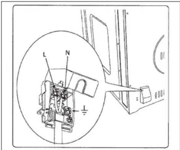
text_image
L N ICher Client,
natural_image
Technical line drawing of a front view of an oven or rack unit with a circular vent and ventilation grilles (no text or symbols)IMPORTANT
natural_image
Technical line drawing of a refrigerator interior showing structural components and mounting brackets (no text or symbols)Important:
natural_image
Interior view of a refrigerator with visible grilles and metal shelves (no text or symbols)PANNEAUX AUTONETTOYANTS
natural_image
Simple line drawing of a five chasing arrow symbol (no text or labels)natural_image
Diagram of airflow or heat transfer through a rectangular chamber with circular vent and fan-like structure (no text or symbols)Cuisson ventilee


natural_image
Top-down schematic of a dual-chamber air vent system (no text or labels)Cuisson au gril


natural_image
Cross-sectional diagram of a room with airflow and ventilation system (no text or labels)REFROIDISSEMENT TANGENTIEL
natural_image
Cross-sectional diagram of a mechanical component with a rotating arrow indicating rotation (no text or symbols)natural_image
Technical line drawing showing two views of a door frame with a hand adjusting the handle (no text or symbols present)Pour l'installateur
text_image
Technical diagram of an electrical switch mechanism with labeled components and a magnified inset showing internal components.Touch control timer, 38
Uhr einstellen, 38
Minutenzähler, 38
Backzeit, 38
natural_image
Technical line drawing of a rectangular appliance with a circular vent and ventilation slots (no text or symbols)WICHTIG
natural_image
Line drawing of a refrigerator interior showing structural components and ventilation slots (no text or symbols)Wichtig:
natural_image
Interior view of an oven with metal grilles and a rack, showing no visible text or symbols.SELBSTREINIGENDE PANEELE
natural_image
Abstract circular arrow symbol composed of five curved arrows forming a ring (no text or labels)natural_image
Diagram of airflow or heat transfer through a rectangular chamber with circular vent and fan-like structures (no text or symbols)Umluft backen


natural_image
Technical line drawing of a mechanical component with symmetrical cutouts and central hub (no text or symbols)Grillen


natural_image
Diagram of airflow around a rectangular chamber with directional arrows indicating flow direction (no text or labels)TANGENTE KÜHLUNG
natural_image
Diagram of a mechanical component with a rotating arrow indicating rotational motion (no text or symbols)natural_image
Line drawing of a hand opening a window frame with a tool, no text or symbols present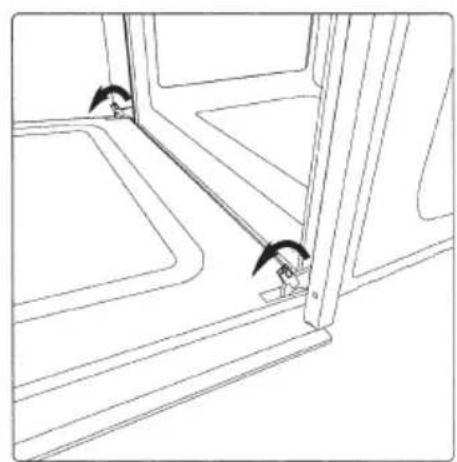
natural_image
Line drawing of a window with two small objects near the door (no text or symbols)text_image
Technical diagram of an electrical component with labeled parts L and N, including a magnified inset showing internal structure.Estimado cliente,
natural_image
Technical line drawing of a front view of an oven or rack unit with a circular vent and ventilation grilles (no text or symbols)IMPORTANTE
natural_image
Technical line drawing of a refrigerator interior showing structural components and mounting holes (no text or symbols)Importante:
natural_image
Interior view of a refrigerator with visible grilles and metal shelves (no text or symbols)natural_image
Simple circular arrow diagram with no text or symbolsnatural_image
Diagram of airflow or heat transfer through a rectangular chamber with circular vent and fan-like structures (no text or symbols)Cocción ventilada:


natural_image
Technical line drawing of a dual-chamber air vent or fan assembly (no text or symbols)Cocción al grill
natural_image
Cross-sectional diagram of a mechanical or electrical component with airflow indicators (no text or symbols)ENFRIAMIENTO TANGENCIAL
natural_image
Diagram of a mechanical component with a rotating arrow indicating rotation (no text or symbols)natural_image
Line drawing of a hand opening a window frame with a black arrow indicating the direction (no text or symbols)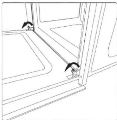
natural_image
Line drawing of a window with two small objects near the door (no text or symbols)Para el instalador
Encastre del horno
text_image
Technical diagram of an electrical switch mechanism with labeled components and a magnified inset showing internal components.Prezado Cliente,
natural_image
Technical line drawing of a rectangular appliance with a circular vent and ventilation slots (no text or symbols)IMPORTANTE
natural_image
Technical line drawing of a refrigerator interior showing structural components and mounting holes (no text or symbols)Importante:
natural_image
Interior view of a refrigerator with visible grilles and metal shelves (no text or symbols)PAINÉIS AUTOLIMPANTES
natural_image
Abstract circular arrow diagram with no text or symbols
natural_image
Diagram of airflow or heat transfer through a rectangular chamber with circular vent and directional arrows indicating flow direction (no text or labels)Modo ventilado


natural_image
Technical line drawing of a mechanical or electrical component with symmetrical arms and central hub (no text or symbols)Modo gril


natural_image
Cross-sectional diagram of a room with airflow and ventilation system (no text or labels)ARREFECIMENTO TANGENCIAL
natural_image
Cross-sectional diagram of a mechanical component with rotational arrow indicating rotation (no text or symbols)natural_image
Technical line drawing showing two views of a door frame with a hand adjusting the handle (no text or symbols present)Para o instalador
Encastre do forno
Cod. 2.002.50.1 - 2ed