
KX-FL611FR - Fax machine PANASONIC - Free user manual and instructions
Find the device manual for free KX-FL611FR PANASONIC in PDF.

User questions about KX-FL611FR PANASONIC
0 question about this device. Answer the ones you know or ask your own.
Ask a new question about this device
Download the instructions for your Fax machine in PDF format for free! Find your manual KX-FL611FR - PANASONIC and take your electronic device back in hand. On this page are published all the documents necessary for the use of your device. KX-FL611FR by PANASONIC.
USER MANUAL KX-FL611FR PANASONIC
natural_image
Line drawing of a printer with paper feed and control panel (no text or symbols)Panasonic
natural_image
Black-and-white photo of two people walking, one holding a newspaper, with blurred background (no visible text or symbols)You can select English for the display and report (feature #48, page 43).
text_image
Illustration showing a hand holding an open notebook with a curved arrow indicating the direction of change, followed by a drop and then a close-up of the open book.natural_image
Black curved arrow pointing left, no text or symbols presentDIFFUSION MANUELLE ③
ENVOI MEMOIRE 8
FAX DEPART 21
IDENTITE APPELANTS IMPR. 17
IDENTITE APPELANTS RECHERCHE 18
MENU 15
NAVIGATEUR 16
NOM/N° TEL 19
PRISE DE LIGNE 12
PROG REPERTOIRE 14
R 11
RECEPTION SELECTIVE 4
REGLAGE 21
RESPONSE AUTO 7
RESOLUTION 6
SECRET COMBINE 10
STOP 20
Panasonic Testing Centre
text_image
Technical diagram of a printer with labeled parts, showing internal structure and numbered annotations.
Unité de fusion
Cartouche d'encre
natural_image
Illustration of a rectangular electronic device with a central slot and top tabs (no text or symbols)⑥
⑦
⑧
⑨
10
natural_image
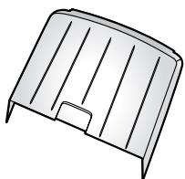
Simple line drawing of a metal door or vent (no text or symbols)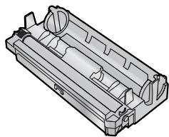
natural_image
Technical line drawing of a mechanical housing component (no text or symbols)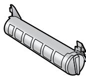

⑪

natural_image
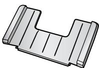
Simple illustration of a folded paper with three horizontal lines (no text or symbols)Remarque:
③ [DIFFUSION MANUELLE]
text_image
Diagram of a printer with numbered parts for identification and assembly reference.natural_image
Illustration of a hand holding a mechanical tool or device with motion lines indicating movement (no text or symbols)natural_image
Illustration of a hand holding a cylindrical object with an arrow indicating direction (no text or symbols present)text_image
Technical diagram showing two stages of a mechanical assembly: top view with component ① and bottom view with component ②, indicating assembly or assembly sequence.natural_image
3D mechanical assembly diagram showing a cylindrical component with internal rollers and directional arrows indicating motion (no text or symbols)natural_image
Mechanical assembly diagram showing a roller roller with directional arrows indicating motion (no text or symbols)natural_image
Technical illustration of a mechanical component with an inset showing a close-up view of a tool interacting with a cylindrical part (no text or symbols present)text_image
Diagram of a printer with labeled parts showing open status and internal mechanism, including a hand pointing to the 'OPEN' button.text_image
Technical diagram of a device with labeled parts, showing internal components and a numbered annotation.text_image
Diagram showing hands installing or adjusting a device into a printer case, with labeled parts ① and ②.text_image
Diagram of a printer with labeled parts, showing front panel and control paneltext_image
Diagram of a printer with labeled parts showing front and back views, including a 3D printer outline.text_image
Diagram showing a printer press operation with numbered steps for handling and handling the printer.Remarque:
natural_image
Illustration of a hand pressing down on a printer with a scroll wheel (no text or symbols visible)text_image
Diagram of a printer with labeled parts showing front, back, and side views for printing or assembly.Remarque:
text_image
Diagram showing the process of printer printing and disassembly steps, with numbered instructions for each step.1.9 Cordon combiné
natural_image
Technical illustration of a portable electronic device with open lid and attached telephone handset (no text or symbols)natural_image
Line drawing of a hand holding a stack of books (no text or symbols present)natural_image
Illustration of a hand inserting a card into a lathe machine (no text or symbols visible)text_image
Diagram of a printer with labeled parts showing front cover and printer tip, including a numbered arrow indicating component ①.text_image
Diagram of a printer with labeled parts showing front, side, and top views of the printer's internal structure.natural_image
Technical line drawing of a mechanical assembly with rollers and frame (no text or symbols)
natural_image
Technical line drawing of a mechanical assembly with no visible text or symbolsnatural_image
Illustration of a lathe machine with a paper feed being inserted, showing no text or symbols on the device itself.natural_image
Illustration of a hand inserting a card into a digital telephone (no text or symbols visible)2.1 Connexions
Attention:
text_image
Diagram of a portable printer with labeled parts and connections, showing open lid, ventilation ducts, and tubing.Remarque:
text_image
[R] [MENU] [◀][▶] [STOP]【REGLAGE】
text_image
RESPONSE AUTORemarque:
text_image
RESPONSE AUTORemarque:
text_image
RESPONSE AUTORéception d'appels
text_image
RESPONSE AUTO [STOP] [FAX DEPART]text_image
RESPONSE AUTOtext_image
RESPONSE AUTO [STOP]text_image
[+][-] [TRI] [STOP] [COPIE DEPART] [RESOLUTION]ACCUSE RECEPT.
=ENVOI INC [±]
ACT.REP.A DIST.
=NON [±]
$$ \begin{array}{l l} \text {JOURNAL AUTO} \ = \text {OUI} & [ \pm ] \end{array} $$
$$ \begin{array}{l} \text { L A N G A G E } \ = \text { F R A N C A I S } \end{array} [ \pm ] $$
FOR ENGLISH USERS: If you want to change the language setting to English, proceed as follows.
- Press [MENU].
- Press [‡], then [4][8].
- Press [+] or [−] repeatedly to select English.
- Press [REGLAGE].
- Press [MENU].
(code : 40-42, 46-72, FF)
NON RESPONSE FAX DIST.
natural_image
Illustration of a hand holding a mechanical device with motion lines indicating movement (no text or symbols)natural_image
Illustration of a hand holding a cylindrical object with a directional arrow indicating motion (no text or symbols)text_image
Diagram of a printer with labeled parts including open status, internal control panel, and paper tray
text_image
Diagram of a mechanical device with labeled parts, showing hands operating a component with numbered annotations.text_image
Technical diagram showing a mechanical assembly process with numbered steps and a magnified detail view.text_image
Technical diagram showing three labeled parts of a mechanical assembly, including a cylindrical component and internal components.text_image
Technical diagram showing two views of a cylindrical device with labeled components and directional arrows indicating assembly or assembly.natural_image
Technical illustration of a mechanical component with directional arrows indicating movement or force (no text or symbols present)natural_image
Mechanical assembly diagram showing a component with directional arrows indicating motion (no text or symbols present)natural_image
Mechanical assembly diagram showing a component with a magnified inset view (no text or symbols)text_image
Technical diagram of a printer with labeled parts, showing internal components and part number ②text_image
Diagram showing a printer folding into a paper holder, with labeled parts and directional arrow indicating rotation.text_image
Diagram of a printer with labeled parts, showing front panel and internal control panel with buttons and dials.text_image
Diagram of a printer with labeled parts including open and closed states, showing internal components and control panel.
Attention:
text_image
Technical diagram of a printer or printer with labeled parts, showing internal structure and component annotations.text_image
Technical diagram of a printer with labeled parts, showing internal structure and assembly stepstext_image
Diagram of printer operation steps showing paper feeding into a printer with labeled parts ①, ②, and ③text_image
Technical diagram of a printer internal structure with labeled parts and zoomed-in insets showing internal components.text_image
Diagram showing mechanical assembly with labeled component '①' and directional arrow indicating motion or forcetext_image
Technical diagram of a printer internal structure with labeled parts and zoomed-in insets showing internal components.text_image
Technical diagram of a printer with labeled parts, showing front panel and control panelnatural_image
Illustration of a printer with paper feed and control panel, no text or symbols presenttext_image
Diagram of a printer with labeled parts showing paper feeding into a stack and print output, with arrows indicating the process.text_image
Diagram showing a printer press operation with labeled parts and directional arrows indicating steps ①, ②, and ③.text_image
Diagram of a printer with labeled parts including open status and internal mechanism, showing internal components and part outline.
text_image
Technical diagram showing a printer's internal structure with labeled parts and an inset view of the component being inserted.natural_image
Technical illustration of a printer with internal components and a numbered label (1), showing no text or symbols beyond the number.text_image
Diagram of a printer with labeled parts, showing front panel and control panel layoutRemarque:
text_image
Illustration of a printer with a prohibition symbol indicating no printing or dischargingtext_image
Diagram of a printer with labeled parts including open status, internal compartments, and part number ①
text_image
Diagram showing hands operating a printer with labeled parts, including a magnified inset of the device's handle.text_image
Technical diagram showing a mechanical assembly with numbered parts and a magnified inset of the component being inserted.text_image
Technical diagram of a printer with labeled parts, showing internal structure and zoomed-in detail viewtext_image
Diagram showing hands operating a device with labeled parts, including a numbered annotation indicating component ①.text_image
Technical diagram of a printer with labeled parts, showing internal components and part number 1text_image
Diagram showing hands operating a printer with a paperclip, labeled with step number ①text_image
Diagram of a printer with labeled parts, showing internal components and directional arrows indicating flow or movement.text_image
Diagram showing a printer with a prohibition symbol indicating no plastic waste or plastic waste.Modified Huffman (MH), Modified READ (MR), Modified Modified READ (MMR)
text_image
THE SLEREXE COMPANY LIMITED SAPARS NAME: WOODS - SANTAR - 8013-524 SALEREXE ROAD (04/12) 1967 - March 2008 Our Ref.: 150/PXC/SING 18th January, 1971. Dr. P.J. Cundall, Hiring Surveys Ltd., Nalysed Road, Hearing Roads: Pour Pete, Fermid no to introduce you to the facility of farmixilla transmission. In farmixilla's phorocell is issued to perform a raster scan over the subject copy. The variations of raster density on the document samples from the phorocell to generate an analogues electrical video signal: This signal is used to navigate a carrier, which is transmitted in a twents destination over a radio or cable communications link. At the remote terminal, demodulation veometrums the video signal, which is used to mediate the density of raster produced by a printing device. This device is ascending as a raster scan symbrimised with that at the transmitting terminal. As a result, a faecalle copy of the subject document is produced. Probably you have sizes for this facility in your organisation. Youth sincerely, Phil. P.J. GABR Group Leader - Faecalle Researchtext_image
Specifications Pain unit specifications 1. Applicable Lines: Public switched telephone network 2. compatibility: 10/-TS (3) 3. Effective Scanning Width: Max. 206mm 4. Recording Paper Size: Letter: 216.278mm Level: .216.356mm 5. Effective Printing Width: 206mm 6. Transmission TimeA: Approx.30sec/page(3 Normal mode,MI) Approx.17sec/page(3 Original mode,MI) Approx.15sec/page(3 Original mode,MI) 7. Fax Serial Times: Up to 95 times 8. Telephone Serial Times: Up to 195 times 9. Scanning Density: Horizontal:8bits/km Vertical: 3.85 lines/wr-Standard mode 7.7 lines/wr/Fines or Ha Phone mode 10. Scanner Type: Contact Image sensortext_image
Specifications Main unit specifications 1. Applicable Lines: Public switched telephone network 2. compatibility: ITU-TS 03 3. Effective Scanning Width: Max: 20Wm 4. Recording Paper Size: Letter: 216 279mm Legal: 216 260mm 5. Effective Printing Width: 206mm 6. Transmission Times: Approx. J/Res/sape(CD Normal node,MI) Approx. J/Res/sape(CD Original node,MI) Approx. J/Res/sape(CD Original node,MI) 7. Fax Bedial Times: Up to 51 times 8. Telephone Redial Times: Up to 15 times 9. Scanning Density: Horizontal Pads/mW Vertical: 3.85 times/sec/Standard node 7.1 times/sec/Time or Halfstone mode 10. Scanner Type: Contact Image sensor 11. Printer Type: Electrophotographic LED array printer 12. Data Compression System: Modified Huffman(MI), Modified Read(MI) 13. Moden Speed: 9800/2000/4800/2400ms Automatic Pallback 14. Operating Environment: 10-32.5 C 20-80x6M 15. Dimensions(H M D): 371 148 489mm 16. Mass(Weight): Approx. 12kg 17. Power Consumption: Standby: Transmission: 17-490V Reception: 12-880V Copy: 24-000V Maximum: 600V *Transmission Time: Transmission lines apply to test data using ITU-TS No.1 test chart between the same models at maximum speed and may vary in actual usage.text_image
Specifications Net unit specifications: 1. Applicable 2. compatibility 3. 375x 100x 100mm 4. Reserving Paper Size 5. Effective Printing Width 6. Transmission Time 7. Printer Type 8. Printer Type 9. Scanning Density 10. Scanner Type: 11. Printer Type 12. Transmission System 13. Mode Speed: 14. Operating Environment: 15. Oension (W D) 16. Protection 17. Power Consumption: 18. Power Supply: 19. Transmission Time: application data using the 15-19 No. 1 text format. Current speed: 300 rpm/min/Hz Current speed: 300 rpm/min/Hz Current speed: 300 rpm/min/Hz Current speed: 300 rpm/min/Hz Current speed: 300 rpm/min/Hz Current speed: 300 rpm/min/Hz Current speed: 300 rpm/min/Hz Current speed: 300 rpm/min/Hz Current speed: 300 rpm/min/Hz Current speed: -100 rpm/min/Hz Current speed: -100 rpm/min/Hz Current speed: -100 rpm/min/Hz Current speed: -100 rpm/min/Hz Current speed: -100 rpm/min/Hz Current speed: -100 rpm/min/Hz Current speed: -100 rpm/min/Hz Current speed: -100 rpm/min/Hz Current speed: -100 rpm/max Current speed: -100 rpm/max Current speed: -100 rpm/max Current speed: -100 rpm/max Current speed: -100 rpm/max Current speed: -100 rpm/max Current speed: -100 rpm/max Current speed: -100 rpm/max Current speed: -100 rpm/max Current speed: -100 rpm/maxGARANTIE CONDITIONS DE GARANTIE
Panasonic Communications (Malaysia) Sdn. Bhd.
PLO No.1, Kawasan Perindustrian Senai, KB No. 104, 81400 Senai, Negeri Johor Darul Ta'zim, Malaysia
Site Web mondial: