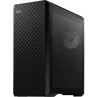
Defender Pro - Desktop Computer XPG - Free user manual and instructions
Find the device manual for free Defender Pro XPG in PDF.


| Product type | Desktop computer (tower) |
| Brand | XPG |
| Model | Defender Pro |
| Dimensions (approx.) | 45 x 20 x 45 cm |
| Weight (approx.) | 8 kg |
| Power supply (approx.) | 500 W |
| Input voltage | 100-240 V AC, 50/60 Hz |
| Main features | High-performance gaming PC, advanced thermal management |
| Care and cleaning | Clean with a clean, damp cloth. Do not use soap or solvent. |
| Operating temperature | 0°C to 40°C |
| Safety | Keep away from liquids and moisture. Do not repair yourself. |
| Warranty | 2 years limited (except exceptions) |
| After-sales service | www.xpg.com for FAQ and support |
| Repairability | Do not attempt repair yourself, contact customer service |
| Spare parts | Contact after-sales service for parts |
| Operating system (typical) | Windows 10 or 11 |
| Processor (typical) | Intel Core i7 or AMD Ryzen 7 |
| RAM memory (typical) | 16 GB DDR4 |
| Storage (typical) | 512 GB SSD |
| Connectivity (typical) | USB 3.0, HDMI, Ethernet |
| Cooling | Fans and heat sink |
Frequently Asked Questions - Defender Pro XPG
User questions about Defender Pro XPG
0 question about this device. Answer the ones you know or ask your own.
Ask a new question about this device
Download the instructions for your Desktop Computer in PDF format for free! Find your manual Defender Pro - XPG and take your electronic device back in hand. On this page are published all the documents necessary for the use of your device. Defender Pro by XPG.
USER MANUAL Defender Pro XPG
ADATA Technology Co., Ltd.
2F, No. 258, Liancheng Rd., Zhonghe Dist., New Taipei City 235, Taiwan
Front I/O Buttons and Ports 05
Installation 07
Warranty Guide 15
PACKAGE CONTENT
- XPG DEFENDER PRO Chassis
- XPG DEFENDER PRO Quick Installation Guide
- Accessory Box
- Brand Card
ACCESSORY BOX CONTENTS


PSU Screws


Motherboard Screws


SSD Screws


Motherboard Standoff Fastening Tool


PCI-E Riser Standoff


Cable Ties


MB Standoff

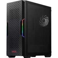
XPG DEFENDER PRO MID-TOWER CHASSIS
A Magnetic Front Panel
B Dust Filter
C Tempered Glass Panel
D 3x XPG VENTO 120 ARGB Fans Included
E 2.5" / 3.5" HDD/SSD Brackets
SPECIFICATIONS
| Color | Black / White |
| Form Factor | Mini-ITX, Micro-ATX, ATX,E-ATX, CEB, EEB |
| Dimensions (W x H x D) | 220 x 492 x 441 mm8.7 x 19.3 x 17.3 inch |
Material SGCC
Side Panel 3mm Tempered Glass (Left Side)
PCI-E Slots 7 Horizontal / 2 Vertical
| 3.5" Drive Bay 2 | |
| 2.5" Drive Bay | 2+2 (Combo 3.5" / 2.5") |
| Fan Mounts | FRONT 140mm x 2 / 120mm x 3TOP 140mm x 2 / 120mm x 2REAR 120mm x 1 |
Fan Pre-Installed XPG VENTO 120 ARGB x3
| Radiator Support | FRONT 360 / 280 / 240mm x 1TOP 280 / 240 / 120mm x 1REAR 120mm x 1 |
| I/O Ports | 2 x USB 3.0 Type A1 x Hybrid Audio Port1x LED Button / 1x Power Button |
| Compatibility | VGA Length Limitation : 380mmCPU Cooler Height Limitation : 170mmPSU Length Limitation : 220mm |
FRONT I/O BUTTONS and PORTS DIMENSIONS and COMPATIBILITY


USB 3.0 x2 Hybrid Audio Port Powen ButtonLED Button
FRONT I/O CABLES
Please consult your user manual of motherboard manufacturer, then connect these leads to the panel header on the motherboard.
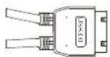
USB 3.0 Connection : Please refer to the motherboard manual for more information on the USB 3.0 connection.

Audio Connection : Please refer to the motherboard installation to avoid the device error and cause the motherboard sound device to be damaged.
PRE-SET LIGHTING EFFECTS
| MODE DESCRIPTIONS | ||||
| Mode 1 Mode | 2 Mode 3 Mode 4 Mode 5 | |||
| Red Green Blue Purple Yellow | ||||
| Mode 6 Mode | 7 Mode 8 Mode 9-13 Mode 13 | |||
| White Orange | Neon Green | Lighting effectNo. 1-4 | Off | |


VGA Length Limitation 380mm
CPU Cooler Height Limitation 170mm
PSU Length Limitation 220mm
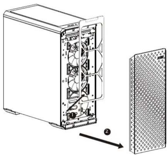
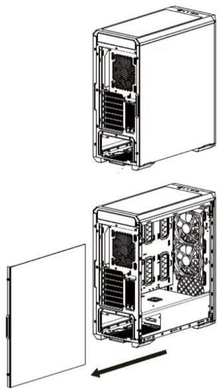
REMOVING THE FRONT PANEL and THE DUST FILTER REMOVING THE GLASS SIDE PANEL
- Detach the Magnetic Front Panel
- Pull the Dust Filter outwards.
natural_image
Technical line drawing of a server rack with internal components and a perforated panel (no text or symbols)07
Manually unscrew the glass side panel, and pull backward with care.
natural_image
Technical line drawing of a computer tower case showing internal components and exterior panel (no text or symbols)08
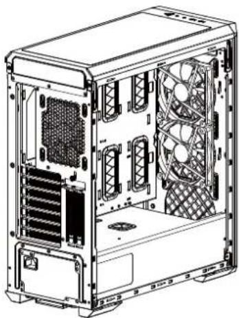
POWER SUPPLY INSTALLATION FAN LOCATIONS and RADIATOR COMPATIBILITY

| Compatibility Chart: Fan | ||
| Location | Quantity | |
| 140mm | 120mm | |
| From | ×2 | ×3 |
| Top | ×2 | ×2 |
| Rear | - | ×1 |
| Pre-Installed Fans:×3 XPS VENTO 120 ARGB | ||
| Compatibility Chart - Radiator | |||
| Radiator Size (mm) | Location | ||
| Furi | Top | Top | |
| 200 | V | - | - |
| 250 | V | V | - |
| 210 | V | V | |
| 140 | V | V | - |
| 120 | V | V | V |
natural_image
Technical line drawing of a computer tower case with visible internal fan and drive slots (no text or labels)STORAGE LOCATIONS
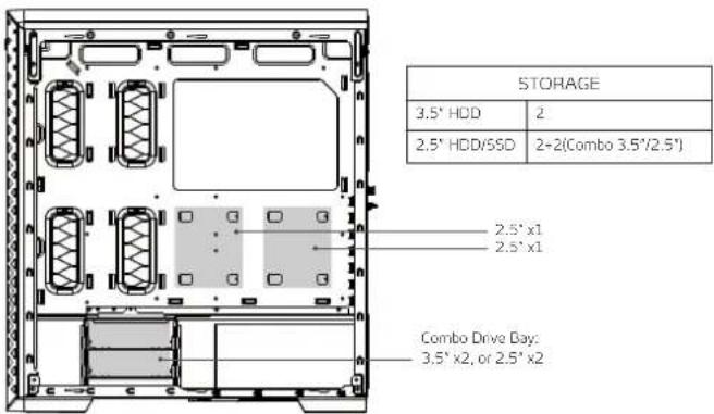
STORAGE LOCATIONS
- Lock-in the 2.5" HDD/SSD Drive.
- Ensure both Drives are firmly installed with the provided screws.

natural_image
Technical line drawings of two server rack units with internal components (no text or symbols)11
STORAGE LOCATIONS : COMBO DRIVES
2 COMBO drive trays are provided for 3.5" HDD and 2.5" HDD/SSD

natural_image
Technical line drawings of internal components of a server or chassis, showing exploded and assembled views (no text or symbols)3.5" HDD Installation 2.5" HDD/SSD Installation
12
INSTALLING PCI-E CARD
Horizontal Installation Vertical Installation

natural_image
Technical line drawing of a computer tower case showing internal components and casing (no text or labels)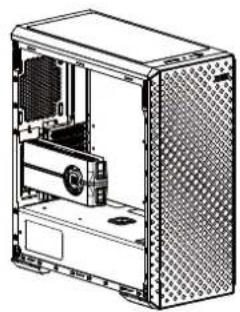
natural_image
Technical line drawing of a computer tower case showing internal components and mounting holes (no text or labels)| PCI-E Slots | 7 Horizontal Slots |
| 2 Vertical Slots |
INSTALLING PCI-E CARD : Horizontally and Vertically
Remove the expansion slot cover, then securely install the PCI-E card.

EN
CLEANING INSTRUCTIONS
Please use a clean damp cloth to clean the product properly.
Do not apply any soap or solvent agent on the surface to preserve its integrity.
SAFETY INSTRUCTIONS
For a proper use of the product, and to ensure your safety, please follow the following instructions:
- Keep the device away from liquids, excess humidity or moisture to avoid any shock hazards. Should the device come into contact with liquids, please make sure to unplug the device immediately, store it in a dry place, and contact support for assistance.
- Operate the device only within the specific temperature range of 0^ C ( 32^ F) to 40^ C ( 104^ F). Should the temperature exceed this range, unplug and/or switch off the device in order to let the temperature stabilize to an optimal level.
- Should you have any other trouble operating the device properly and normal troubleshooting does not work, please unplug the device and contact our service for support.
- Do not attempt to service or fix the device by yourself at any time.
DURATION OF WARRANTY
ADATA Technology Co., Ltd. provides a two-year warranty period for this product unless regional laws and regulations state otherwise.
LIMITATION OF WARRANTY
This limited warranty covers only repairs or replacements of products manufactured by ADATA Technology Co. Ltd. and its authorized partners.
Please note that ADATA is responsible for providing free repairs except for the following reasons:
- The warranty label is altered, damaged or missing.
- Product serial number does not conform to our original system.
- Products purchased from an unauthorized agent.
- Damage caused by natural calamity
- Any abuse outside the intended product operation.
ONLINE CUSTOMER SERVICE
For frequently asked questions, additional information and service instruction please visit the product page at www.xpg.com
15
DE

- PACKAGE CONTENT
- ACCESSORY BOX CONTENTS
- XPG DEFENDER PRO MID-TOWER CHASSIS
- FRONT I/O BUTTONS and PORTS DIMENSIONS and COMPATIBILITY
- FRONT I/O CABLES
- PRE-SET LIGHTING EFFECTS
- REMOVING THE FRONT PANEL and THE DUST FILTER REMOVING THE GLASS SIDE PANEL
- POWER SUPPLY INSTALLATION FAN LOCATIONS and RADIATOR COMPATIBILITY
- STORAGE LOCATIONS
- STORAGE LOCATIONS : COMBO DRIVES
- INSTALLING PCI-E CARD
- INSTALLING PCI-E CARD : Horizontally and Vertically
- CLEANING INSTRUCTIONS
- SAFETY INSTRUCTIONS
- DURATION OF WARRANTY
- LIMITATION OF WARRANTY
- ONLINE CUSTOMER SERVICE
Brand : XPG
Model : Defender Pro
Category : Desktop Computer