X850 - Audio Amplifier Paradigm - Free user manual and instructions
Find the device manual for free X850 Paradigm in PDF.

User questions about X850 Paradigm
0 question about this device. Answer the ones you know or ask your own.
Ask a new question about this device
Download the instructions for your Audio Amplifier in PDF format for free! Find your manual X850 - Paradigm and take your electronic device back in hand. On this page are published all the documents necessary for the use of your device. X850 by Paradigm.
USER MANUAL X850 Paradigm
IMPORTANT! Amplifiers covered by this manual are designed for use with matching Paradigm® and Paradigm® Reference in-wall/in-ceiling subwoofer only. Use with any other brand of subwoofer can cause permanent damage and will void the Paradigm warranty.

Paradigm
OWNERS MANUAL OM-620
X-SERIES AMPLIFIERS
Thank you for choosing Paradigm® X-Series amplifiers and congratulations! You are about to hear the difference your new subwoofer system will make in a music and home theater setup.
These systems are the product of countless hours of comprehensive research and development and will reward you with exceptional performance for many years.
To achieve all of the performance they are capable of providing requires care in installation and operation. Please take the time to read this manual as well as the manual included with your new subwoofer and follow all instructions. If you have further questions, please contact your Authorized Paradigm® or Paradigm® Reference Dealer or check the Q&A page in the Tech Support section of our website at www.paradigm.com.

TABLE OF CONTENTS
Safety Precautions 2
Important Safety Instructions 3
Important Operating Instructions 4
Amplifier In-Use Notices 5
Amplifier Parts List 51
Attaching Rack-Mount Handles (Pictorial) 5
Panel Layouts (Pictorialis) 6
Impedance Matching Switch (Pictorial) 7
3-Position "EQ" Switch (Pictorial) 7
Connecting (Pictorial) 8
Your New System 9
Configuring Your Amplifier 9
Power Requirements 10
Subwoofer Connection 10
Fine Tuning 11
Limited Warranty 12
SAFETY PRECAUTIONS
READ THIS SECTION CAREFULLY BEFORE PROCEEDING!
WARNING
RISK OF ELECTRIC SHOCK DO NOT OPEN

The lightning flash with arrowpoint within an equilateral triangle warns of the presence of uninsulated "dangerous voltage" within the product's enclosure that may be of sufficient magnitude to constitute a risk of electric shock to persons.
WARNING: TO REDUCE THE RISK OF ELECTRIC SHOCK, DO NOT REMOVE COVER (OR BACK). NO USER-SERVICEABLE PARTS INSIDE. REFER SERVICING TO QUALIFIED SERVICE PERSONNEL.

The exclamation point within an equilateral triangle warns users of the presence of important operating and maintenance (servicing) instructions in the literature accompanying the appliance.
WARNING: TO REDUCE THE RISK OF FIRE OR ELECTRIC SHOCK, DO NOT EXPOSE THIS APPARATUS TO RAIN OR MOISTURE, AND OBJECTS Filled WITH LIQUIDS, SUCH AS VASES, SHOULD NOT BE PLACED ON THIS APPARATUS.
CAUTION: TO PREVENT ELECTRIC SHOCK, MATCH WIDE BLADE OF PLUG TO WIDE SLOT, FULLY INSERT.
CAUTION: FOR CONTINUED PROTECTION AGAINST RISK OF FIRE, REPLACE THE FUSE ONLY WITH THE SAME AMPERAGE AND VOLTAGE TYPE. REFER REPLACEMENT TO QUALIFIED SERVICE PERSONNEL.
WARNING: UNIT MAY BECOME HOT. ALWAYS PROVIDE ADEQUATE VENTILATION TO ALLOW FOR COOLING. DO NOT PLACE NEAR A HEAT SOURCE, OR IN SPACES THAT CAN RESTRICT VENTILATION.
IMPORTANT SAFETY INSTRUCTIONS
- Read Instructions - All the safety and operating instructions should be read before the product is operated.
- Retain Instructions - The safety and operating instructions should be retained for future reference.
- HeedWarnings - All warnings on the product and in the operating instructions should be adhered to.
- Follow Instructions - All operating and use instructions should be followed.
- Cleaning - Unplug this product from the wall outlet before cleaning. Do not use liquid cleaners or aerosol cleaners. Use a damp, soft cloth for cleaning.
- Water and Moisture - Do not use this product near water-for example, near a bath tub, wash bowl, kitchen sink, or laundry tub; in a wet basement; or near a swimming pool; and the like.
- Accessories - Do not place this product on an unstable cart, stand, tripod, bracket, or table. The product may fall, causing serious injury to a child or adult, and serious damage to the product. Use only with a cart, stand, tripod, bracket, or table recommended by the manufacturer, or sold with the product. Any mounting of the product should follow manufacturer's instructions, and should use a mounting accessory recommended by the manufacturer.
- Ventilation - Slots and openings in the cabinet are provided for ventilation and to ensure reliable operation of the product and to protect it from overheating, and these openings must not be blocked or covered. The openings should never be blocked by placing the product on a bed, sofa, rug, or other similar surface. This product should not be placed in a built-in installation such as a bookcase or rack unless proper ventilation is provided or the manufacturer's instructions have been adhered to.
- Power Sources - This product should be operated only from the type of power source indicated on the marking label. If you are not sure of the type of power supply to your home, consult your product dealer or local power company. For products intended to operate from battery power, or other sources, refer to the operating instructions.
- Grounding and Polarization - This product may be equipped with a polarized alternating-current line plug (a plug having one blade wider than the other). This plug will fit into the power outlet only one way. This is a safety feature. If you are unable to insert the plug fully into the outlet, try reversing the plug. If the plug should still fail to fit, contact your electrician to replace your obsolete outlet. Do not defeat the safety purpose of the polarized plug.
- Power-cord Protection - Power-supply cords should be routed so that they are not likely to be walked on or pinched by items placed upon or against them, paying particular attention to cords at plugs, convenience receptacles, and the point where they exit from the product.
- Outdoor Antenna Grounding - If an outside antenna or cable system is connected to the product, be sure the antenna or cable system is grounded so as to provide some protection against voltage surges and built-up static charges. Article 810 of the National Electrical Code, ANSI/NFPA 70, provides information with regard to the proper grounding of the mast and supporting structure, grounding of the lead-in wire to an antenna-discharge unit, size of grounding conductors, location of antenna-discharge unit, connection to grounding electrodes, and requirements for the grounding electrode.
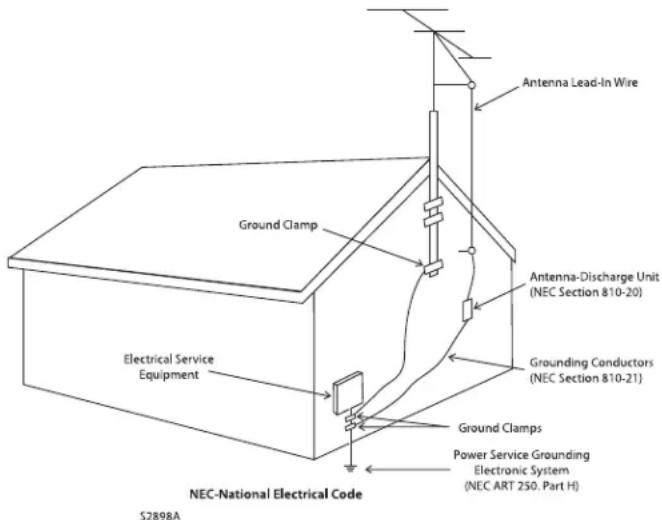
- Lightning - For added protection for this product during a lightning storm, or when it is left unattended and unused for long periods of time, unplug it from the wall outlet and disconnect the antenna or cable systems. This will prevent damage to the product due to lightning and power-line surges.
- Power Lines - An outside antenna system should not be located in the vicinity of overhead power lines or other electric light or power circuits, or where it can fall into such power lines or circuits. When installing an outside antenna system, extreme care should be taken to keep from touching such power lines or circuits as contact with them might be fatal.
- Overloading - Do not overload wall outlets, extension cords, or integral convenience receptacles as this can result in a risk of fire or electric shock.
- Object and Liquid Entry - Never push objects of any kind through openings as they may touch dangerous voltage points or short-out parts that could result in a fire or electric shock. Do not expose this product to dripping or splashing and ensure that no objects filled with liquids, such as vases, are placed on the product.
- Servicing - Do not attempt to service this product yourself, as opening or removing covers may expose you to dangerous voltage or other hazards. Refer all servicing to qualified service personnel.
-
Damage Requiring Service - Unplug this product from the wall outlet and refer servicing to qualified personnel under the following conditions:
-
When power-supply cord or plug is damaged;
If liquid has been spilled, or objects have fallen into the product; - If the product has been exposed to rain or water;
- If the product does not operate normally by following the operating instructions. Adjust only those controls that are covered by the operating instructions as an improper adjustment of other controls may result in damage and will require extensive work by a qualified technician to restore the product to its normal operation;
If the product has been dropped or damaged in any way;
If the product exhibits a distinct change in performance--this indicates a need for service.
IMPORTANT SAFETY INSTRUCTIONS (continued)
- Replacement Parts - When replacement parts are required, be sure the technician has used replacement parts specified by the manufacturer or have the same characteristics as the original part. Unauthorized substitutions may result in fire, electric shock, or other hazards.
-
Safety Check - Upon completion of any service or repairs to this product, ask the service technician to perform safety checks to determine that the product is in proper operating condition.
-
Heat - The product should be situated away from heat sources such as radiators, heat registers, stoves, or other products (including amplifiers) that produce heat.
IMPORTANT OPERATING INSTRUCTIONS
TO PREVENT DAMAGE TO AMPLIFIER OR SUBWOOFER, FOLLOW THE INSTRUCTIONS THAT RELATE TO YOUR SETUP BELOW. FAILURE TO FOLLOW THESE INSTRUCTIONS WILL RESULT IN PERMANENT DAMAGE TO AMPLIFIER AND SUBWOOFER. SUCH DAMAGE IS NOT COVERED UNDER THE PARADIGM WARRANTY.
USING YOUR AMPLIFIER WITH A 'REFERENCE' RVC SUBWOOFER:

TO PREVENT DAMAGE TO AMPLIFIER OR SUBWOOFER, THE IMPEDANCE MATCHING SWITCH ON YOUR 'REFERENCE' RVC SUBWOOFER'S BAFFLE MUST BE CORRECTLY POSITIONED (See Fig. 2).
USING AN X-300 AMPLIFIER:

TO ENSURE OPTIMAL SOUND AND PREVENT DAMAGE TO AMPLIFIER OR SUBWOOFER, THE 3-POSITION "EQ" SWITCH ON THE X-300'S REAR PANEL MUST BE CORRECTLY CONFIGURED (See Fig. 3). Additional details on page 9.


ALL MODELS
- DO NOT connect to power if there are any signs of damage to any part of the exterior.
- Depending on the level of the input signal, the voltage at the outputs can be high enough to cause electric shock. Turn all components OFF before connecting the amplifier.
-
Allow adequate ventilation to ensure reliable operation and prevent overheating. The amount of space required above the unit for radiation depends on ambient air temperature and circulation. Installation inside a cabinet with a front that can be closed is NOT recommended unless a fan is installed to adequately draw air away from the top of the unit.
-
Failing to comply with any safety instruction, precaution or warning in this Operating Manual is in direct violation of the standards of design, manufacture and intended use of this product. Paradigm and any related party assume no liability for the user's failure to comply with these requirements.


AMPLIFIER IN-USE NOTICES
(all models)
- Disconnect the power cord before connecting or disconnecting any components.
- DO NOT remove top cover: there are no user-serviceable parts inside.
-
DO NOT modify the product.
-
The Auto-On/Trigger switch on the rear panel of selected models will NOT turn the amplifier off or disconnect it from the AC line source. It can only initiate the amplifier's standby mode. It is necessary therefore to ensure the power cord remains readily accessible at all times.
AMPLIFIER PARTS LIST (all models)
- 1 Subwoofer amplifier
- 1 Detachable power cord
- 1 Tempered glass faceplate (attaches to front panel magnetically)
-
2 Rack-mount handles with 6 screws (assembly required); optional use
-
1 Setup CD for configuration of amplifier (X-850 only)
- 1 USB card (X-850 only)
Required, not included
- 1 Slohead screwdriver to facilitate adjustment of subwoofer controls
ATTACHING RACK-MOUNT HANDLES (optional use)
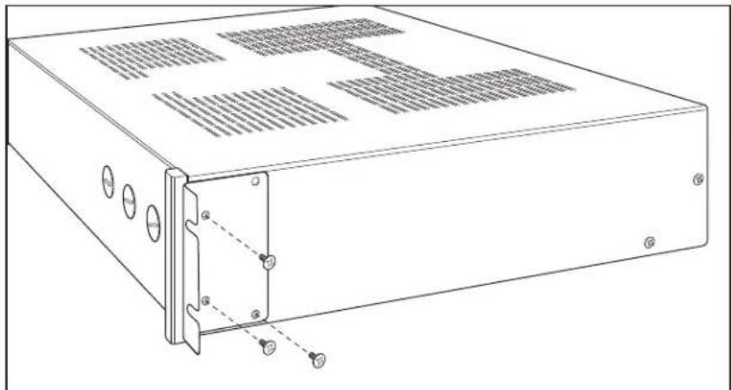
Fig. 1
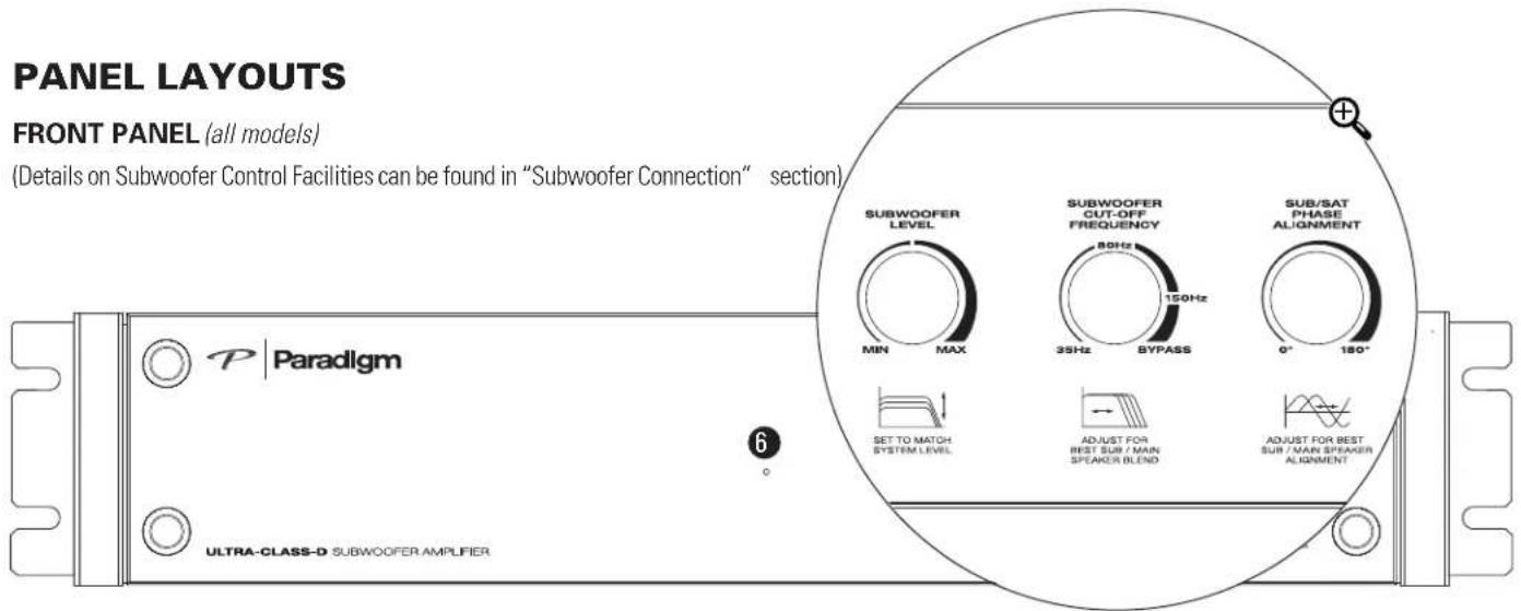
PANEL LAYOUTS
FRONT PANEL (all models)
(Details on Subwoofer Control Facilities can be found in "Subwoofer Connection" section),
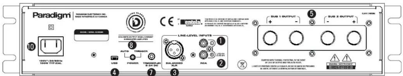
BACK PANEL (by model)
X-300 AMPLIFIER
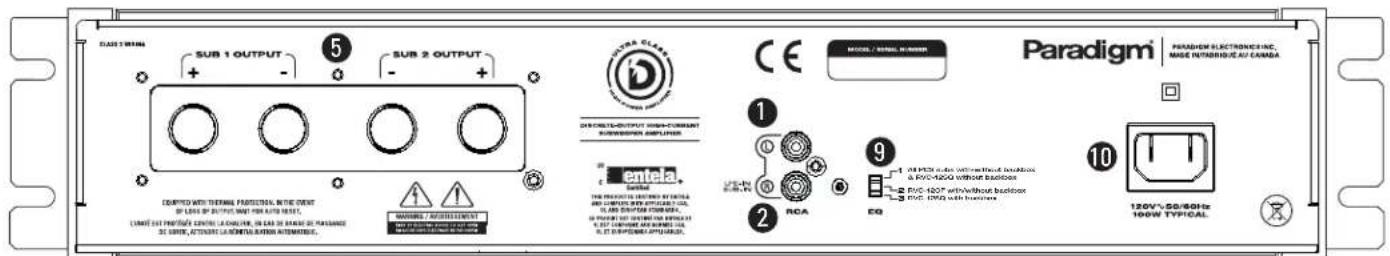
X-850 AMPLIFIER
(varies by model)
INPUTS
- Single-Ended RCA Inputs
- Sub-In Right (Mono) Input
- Balanced XLR Input
- USB Input
OUTPUTS
- SUB 1/SUB 2 Outputs
POWER
- LED
- Trigger-In
- Auto-On/Trigger-On
9.3-Position "EQ" Switch - Power Cord Connection
Single Interior Fuse (not shown); not serviceable by user. (For servicing contact your Dealer, or outside of North America your Paradigm® Distributor)
IMPEDANCE MATCHING SWITCH (Reference RVC Subwooers only)
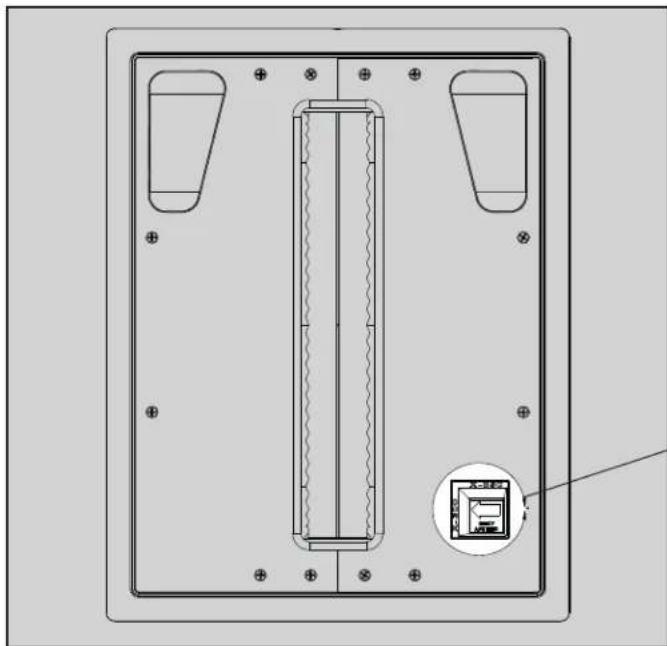
Fig. 2


or
X-850
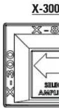
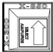
3-POSITION "EQ" SWITCH (X-300 Amplifier only)

Fig. 3


EQ
1 All PCS subs with/without backbox & RVC-12SQ without backbox
2 RVC-12CF with/without backbox 3 RVC-12SQ with backbox
CONNECTING (Balanced XLR input applies to X-850 model only)
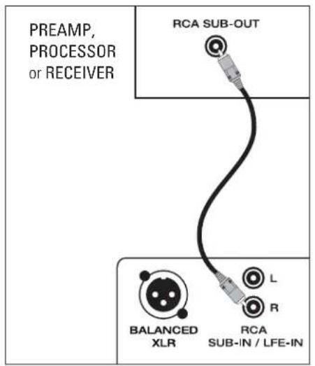
Fig. 4a
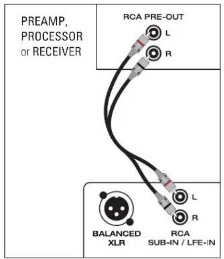
Fig. 4b Fig. 5
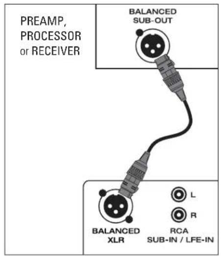
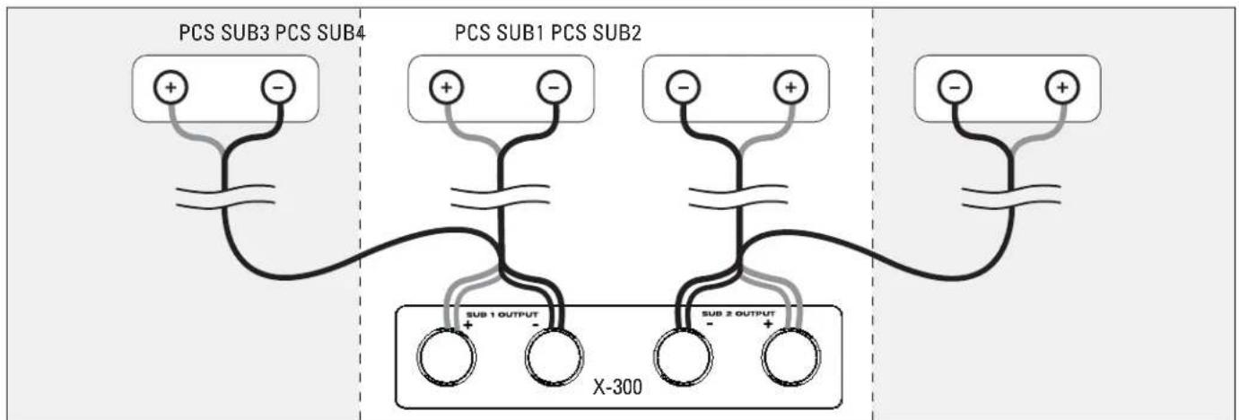
Fig.6a X-300 Amp / 2 PCS Subs or 4 PCS Subs
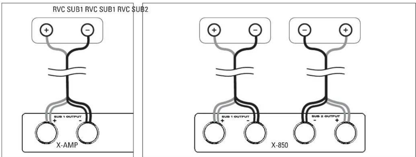
Fig. 6b X-300 or X-850 Amp/1 RVC Sub
Fig.6c X-850 Amp/2 RVC Subs
YOUR NEW SYSTEM
Break-In
Although your Paradigm® or Paradigm® Reference amplifier/subwoofer system will sound great "out of the carton," it will sound even better when broken in. Read through this manual and the manual included with your new subwoofer before beginning to set up your system to make sure you are getting all the high-end performance your system has to offer.
Optional Rack Mounting
Your new amplifier comes with rack-mount handles allowing you to mount it in an A/N rack, if desired (rack not included). See Fig. 1 for easy assembly.
Cleaning and Care
Your X-Series amplifier has a very durable finish. To clean, simply wipe it with a dry soft cloth.
CONFIGURING YOUR AMPLIFIER

IMPORTANT! Before setting up your system be sure to read all Safety Precautions and Safety and Operating Instructions included at the beginning of this manual.
The following chart indicates the quantity of corresponding subwoofoers that can safely be matched with your amplifier. Follow the chart to achieve optimal sound:
| AMPLIFIER MODEL | SUBWOOFER MODEL AND QUANTITY |
| One X-300 Amplifier: | 2 to 4 Paradigm® PCS subwooers or 1 Paradigm® Reference RVC subwoofer |
| One X-850 Amplifier: | Up to 2 Paradigm® Reference RVC subwooers |

WARNING: The following three procedures are imperative for correct system setup. Failure to follow the instructions that apply to your setup will result in permanent damage to amplifier and subwoofer. Such damage is NOT covered under the Paradigm warranty.

1.Using Your Amplifier with a Reference'RVC Subwoofer:
To prevent damage to amplifier or subwoofer, the Impedance Matching Switch on your 'Reference' RVC subwoofer's baffle must be correctly positioned (Fig. 2).
2.Using an X-300 Amplifier:
To prevent damage to amplifier or subwoofer and ensure optimal sound, the 3-Position "EQ" Switch on the X-300's rear panel must be correctly positioned for use with or without a Paradigm® Backbox (sold separately). Toggle to the setting that matches your setup (Fig. 3):
Setting 1: Use this setting with:
All PCS Series subwoofoers with or without a backbox or
One RVC-12SQ subwoofer without a backbox
Setting 2: Use this setting with:
One RVC-12CF subwoofer with or without a backbox
Setting 3: Use this setting with:
One RVC-12SQ subwoofer with a backbox
NOTE: These settings are also displayed on your amplifier's back panel.
3. Setup CD included with your X-850 Amplifier:
Your X-850 amplifier comes with a Setup CD that allows you to configure your subwoofer for optimal sound. Install the software and perform the setup before connecting your amplifier to the subwoofer.
Installing the Software:
(PC requirements are Windows XP or Vista; USB port)
- Insert the Setup CD into your computer's CD or DVD drive. Installation instructions will appear on your screen. If your computer does not allow a CD to 'auto-run', double-click on the 'My Computer' icon on your computer desktop and select the CD drive, open it and double-click on setup.exe.
- The installation process will install several files into a Paradigm folder on your computer and create shortcuts on your Start Menu. Locate the shortcut on the Start Menu (under the Paradigm folder). Shortcut name will be 'X-850 Configurator.' Launch the application.
- You will be presented with a list of options for setup, select the one that matches your setup and follow the instructions on the screen.
POWER REQUIREMENTS
The "Watts" (W) rating indicated on the amplifier's rear panel is the typical power your amplifier will draw during normal use. However, when producing its maximum power output, the actual wattage draw will vary with the bass content of the program material—more if there is a lot of deep bass, less when there is not as much bass.
WANT TO USE MORE THAN ONE X-850 AMPLIFIER? In this case, we recommend connecting each amplifier to its own AC circuit.
THERMAL PROTECTION: X-Series amplifiers are equipped with a thermal protection feature. In the event of loss of output wait for automatic reset.
SUBWOOFER CONNECTION

IMPORTANT! Before proceeding with this section, be sure to read all Safety Precautions and Safety and Operating Instructions included at the beginning of this manual.
NOTE: Speakers set to "Large" with your processor or A/V receiver will still be reproducing bass frequencies—be careful not to overdrive them!
We recommend the use of high-quality cables and connectors. (See your Dealer for more information.)


Turn all components OFF before connecting the amplifier.
This Owners Manual applies to more than one Paradigm® X-Series amplifier. Connection options vary by model. Examine your amplifier's rear panel to
determine the input(s) that apply to your model, then choose the one that best suits your needs.
Input Facilities
Line-Level RCA Input (Figs. 4a - 4b)
- Mono Input (Left, Right, or Sub-Out) connects from the RCA (S/E) Sub/ LFE-Output of your Preamplifier/Processor, A/V Receiver or other suitable line-level source (Fig. 4a).
- Stereo Input (Left & Right) connects from the Stereo Preamplifier, Stereo Receiver or other suitable line-level stereo source (Fig. 4b).
NOTE: DO NOT use RCA-compatible connectors that have a hollow center pin with a hole at the tip—inserting these into the amplifier's RCA jacks can cause internal damage.
Line-Level Input—Balanced XLR (Fig. 5)
Connects from the Balanced XLR Sub/LFE Output of your Preamplifier/ Processor, A/V Receiver or other suitable line-level source. This input provides the lowest noise and distortion possible. It is particularly important for long cable runs where noise and distortion could degrade performance.
The USB Port
The X-850 amplifier has a USB port, it will allow for:
- Configuring your system for optimal sound with or without a Paradigm® Backbox (sold separately), using the setup CD included with amplifier;
Future upgrades to software installed in your subwoofer;
- Use with the Paradigm Perfect Bass Kit ™ Digital Room Correction system (sold separately).
Output Facilities and Connection Options
SUB 1 Output and SUB 2 Output (Figs. 6a - 6c)
Connecting Two PCS Subwoofer (Fig. 6a): Connect Red (+) speaker cable to positive SUB 1 (+) Output and Black (-) speaker cable to SUB 1 (-) Output. For second subwoofer, connect Red (+) speaker cable to positive SUB 2 (+) Output and Black (-) speaker cable to SUB 2 (-) Output.
Connecting Four PCS Subwoofoers (Fig. 6a): Connect Red (+) speaker cable to positive SUB 1 (+) Output and Black (-) speaker cable to SUB 1 (-) Output. For second subwoofer, connect Red (+) speaker cable to positive SUB 2 (+) Output and Black (-) speaker cable to SUB 2 (-) Output. For third and fourth subwoofoers, repeat instructions in same order.
Connecting One RVC Subwoofer (Fig. 6b): Connect Red (+) speaker cable to positive SUB 1 (+) Output and Black (-) speaker cable to SUB 1 (-) Output.
Connecting Two RVC Subwooers (Fig. 6c): Connect Red (+) speaker cable to positive SUB 1 (+) Output and Black (-) speaker cable to SUB 1 (-) Output. For second subwoofer, connect Red (+) speaker cable to positive SUB 2 (+) Output and Black (-) speaker cable to SUB 2 (-) Output.
NOTE: If you are connecting more than two RVC subwoofoers you will require an additional X-850 amplifier, connected to its own AC circuit.
SUBWOOFER CONNECTION (continued)
Control Facilities
This Owners Manual applies to more than one X-Series amplifier. Examine your amplifier's front and rear panels and place a check mark in the box beside each facility listed below that applies to your model. Before you begin to fine tune your system, read through the control descriptions and become familiar with them.
Auto-On/Off
Eliminates need for a manually operated power switch. Turns the subwoofer on when there is an input signal. If no input signal is sensed after a period of 20 minutes the subwoofer will turn off automatically.
Trigger-In
Allows power on/off to be controlled remotely by components that have trigger outputs.
Subwoofer Level
Balances the subwoofer's output level with the other speakers in your system. Once set, to make on-the-fly changes for particular program material or personal taste, use your Processor's or A/V Receiver's subwoofer level control.
Subwoofer Cut-Off with Bypass Option
Controls the subwoofer's upper-frequency cut-off. This can be set to match the low-frequency roll-off characteristics of your system's speakers. For example: If your speakers play to approximately 80Hz , you can set the subwoofer cut-off frequency to approximately 80Hz . If you are using an external subwoofer cut-off control, set this control to "Bypass".
Bypass option allows you to bypass the subwoofer's built-in cut-off control to let your preamp/processor's or receiver's internal bass management system provide the crossover function.
Phase Alignment
Depending on where the subwoofer is placed in your room, there may be bass frequency cancellation. This can occur because your subwoofer and front speakers are out-of-phase—they work against each other through their frequency overlap region. Bass is then reduced and may even sound disjointed. This control accurately synchronizes your subwoofer and front speakers through their bass frequency overlap region.
FINE TUNING
When fine tuning your subwoofer to best integrate with the rest of your system use music and video soundtracks that you know well. They should contain selections with extended bass that is continuous and repetitive.
Assess subwoofer bass output for best blend with your main speakers. It should not be overbearing or draw attention to itself, nor should it be thin and difficult to hear. It should add "weight" and "punch" to the overall sound and keep pace with your main speakers.
If you are using a receiver, preamplifier or preamp/processor with tone controls, set them to flat (i.e. "0") and switch loudness controls off.
Some subwoofer locations may result in bass frequency cancellations. If bass sounds dislocated or weak, adjust the phase according to the Phase Alignment Control instructions that follow.
Setting Subwoofer Controls
For convenience, the Subwoofer Controls are located on the front panel of the amplifier. You will require a standard slothead screwdriver (not included) to adjust these controls:
- Turn the Subwoofer Level control completely counter-clockwise to its minimum;
- Turn the Subwoofer Cut-off Frequency control to its highest frequency (i.e. 150Hz );
- Turn the Phase Alignment control to 0^ (completely counter-clockwise);
- Listen to a bass music or video selection while seated in your primary listening area and have an assistant turn up the Subwoofer Level control until the subwoofer can be clearly heard;
-
Have an assistant slowly rotate the Phase Alignment control until you hear the most bass. Your subwoofer and front speakers are now in phase. Do not change phase alignment again unless you move the subwoofer or front speakers to a different location in your room, or move or remove any large items of furniture or room furnishings (i.e. carpet, draperies, etc.);
-
Turn the Subwoofer Level control completely counter-clockwise to its minimum;
- Turn the Subwoofer Cut-off Frequency control to its lowest frequency (i.e. 50 Hz);
- Slowly rotate the Subwoofer Level control until you match the subwoofer's volume with the volume of your front speakers. Bass should be clearly audible, but not intrusive;
OPTIONAL BYPASS FEATURE: If you are using an A/V receiver or processor to control crossover setting, skip the next step and simply set the subwoofer cut-off frequency control to "Bypass".
- Slowly rotate the Subwoofer Cut-off Frequency control until you hear the best subwoofer/front speaker blend. If the sound is too thin you have not set the frequency high enough; if the sound becomes boomy you have set the frequency too high. Adjust until you find the most natural bass balance.
- Attach glass faceplate to front panel.
LIMITED WARRANTY
IMPORTANT! Amplifiers covered by this manual are designed for use with matching Paradigm® and Paradigm® Reference in-wall/ in-ceiling subwoofoers only. Use with any other brand of subwoofer can cause permanent damage and will void the Paradigm warranty.
Paradigm and Paradigm Reference amplifiers are warranted to be and remain free of manufacturing and/or material defects for a period of three (3) years from the date of the original retail purchase. Within this specified period, repair, replacement or adjustment of parts for manufacturing and/or material defects will be free of charge. Thermal or mechanical abuse/ misuse is not covered under warranty.
Limitations:
- Warranty begins on date of original retail purchase from an Authorized Paradigm® or Paradigm® Reference Dealer only. It is not transferable;
- Warranty applies to product in normal home use only. If the product is subjected to any of the conditions outlined in the next section, warranty is void;
- Warranty does not apply if the product is used in professional or commercial applications.
Warranty is Void if:
The product has been abused (intentionally or accidentally);
- The product has been used in conjunction with unsuitable or faulty equipment;
- The product has been subjected to damaging signals, derangement in transport, mechanical damage or any abnormal conditions;
- The product has been tampered with or damaged by an unauthorized service facility;
The serial number has been removed or defaced.
Owner Responsibilities:
- Provide normal/reasonable operating care and maintenance;
- Provide or pay for transportation charges for product to service facility;
- Provide proof of purchase (your sales receipt given at time of purchase from your Authorized Paradigm® Reference Dealer).
Should servicing be required, contact your nearest Authorized Paradigm® or Paradigm® Reference Dealer, Paradigm Electronics Inc., or Import Distributor (outside the U.S. and Canada) to arrange, bring in or ship prepaid any defective unit. Visit our website at www.paradigm.com for more information.
Paradigm Electronics Inc. reserves the right to improve the design of any product without assuming any obligation to modify any product previously manufactured.
This warranty is in lieu of all other warranties expressed or implied, of merchantability, fitness for any particular purpose and may not be extended or enlarged by anyone. In no event shall Paradigm Electronics Inc., their agents, or representatives be responsible for any incidental or consequential damages. Some jurisdictions do not allow limitation of incidental or consequential damages, so this exclusion may not apply to you.
Retain this manual and your sales receipt for proof of warranty term and proof of purchase.

- SUB 1/SUB 2 Outputs / Sorties SUB 1/SUB 2
POWER / ALIMENTATION
SUB 1 Output and SUB 2 Output (Figs. 12a - 12c)
In accordance with the European Union WEEE (Waste Electrical and Electronic Equipment) directive effective August 13, 2005, we would like to notify you that this product may contain regulated materials which, upon disposal, according to the WEEE directive, require special reuse and recycling processing. For this reason Paradigm Electronics Inc. Manufacturers of Paradigm®speakers and Anthem®electronics has arranged with our distributors in European Union member nations to collect and recycle this product at no cost to you. To find your local distributor please contact the dealer from whom you purchased this product or go to our website at www.paradigm.com.
Please note that the product only falls under the WEEE directive. When disposing of packaging and other shipping material we encourage you to recycle through the normal channels.