
TXA604SW - Speaker Monacor - Free user manual and instructions
Find the device manual for free TXA604SW Monacor in PDF.
User questions about TXA604SW Monacor
0 question about this device. Answer the ones you know or ask your own.
Ask a new question about this device
Download the instructions for your Speaker in PDF format for free! Find your manual TXA604SW - Monacor and take your electronic device back in hand. On this page are published all the documents necessary for the use of your device. TXA604SW by Monacor.
USER MANUAL TXA604SW Monacor
Portable Active Speaker System with Receiver for 2 Wireless Microphones

text_image
MONACOR WWW.MONACOR.COM863,1 MHz - 864,9 MHz
natural_image
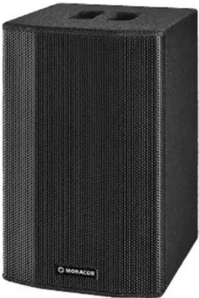
Black perforated audio amplifier box with two spout holes, labeled 'MONACOR' (no other text or symbols visible)TXA-604/SW
English ...... Page 10
Français .... Page 16
3 Applications and Accessories ..... 11
3.1 Wireless microphones and transmitters. . 12
3.2 Conformity and approval.....12
4 Setting into Operation ..... 12
4.1 Setting up the active speaker system . . . 12
4.2 Power supply.....12
4.3 Connecting the active speaker system . . 12
5 Operation....13
5.1 Operation of the receiver module .....13
5.1.1 Setting the transmission channels. . . . 13
5.1.2 Adjusting the volume.....13
5.1.3 Setting the squelch ..... 13
5.2 Limiter .....14
5.3 Volume attenuation during microphone announcements ..... 14
6 Specifications....14
text_image
UHF-Duo 10110Ω OFF CHA SET OFF CH.B 1322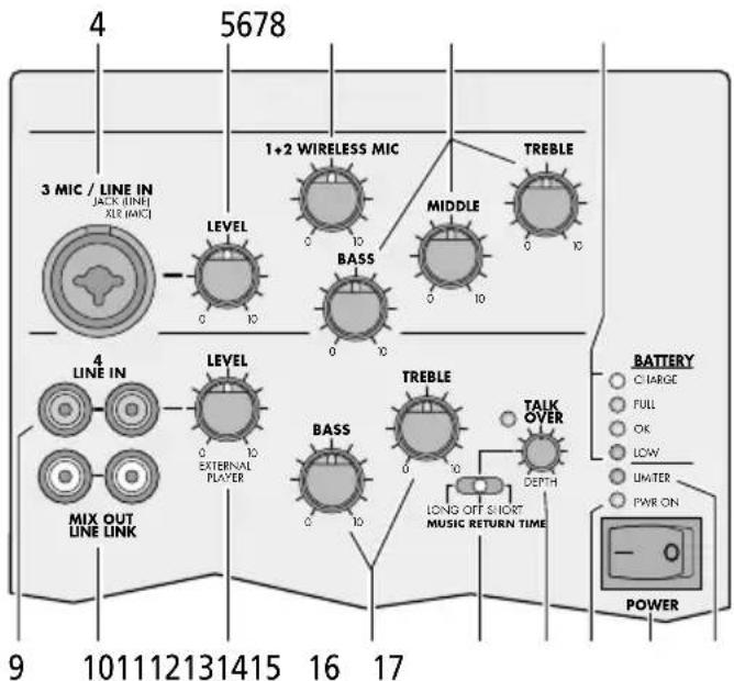
text_image
4 5678 3 MIC / LINE IN JACK (LINE) XLR (MAC) LEVEL 1+2 WIRELESS MIC MIDDLE TREBLE BASS 0 10 0 10 0 10 0 10 0 10 4 LINE IN LEVEL BASS TREBLE TALK OVER LONG OFF SHORT MUSIC RETURN TIME 0 10 0 10 0 10 0 10 9 101112131415 16 17 BATTERY CHARGE FULL OK LOW UMETER PWR ON POWER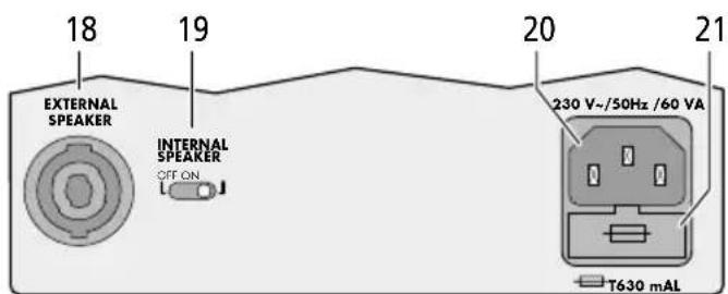
text_image
18 19 20 21 EXTERNAL SPEAKER INTERNAL SPEAKER OFF ON 230 V-/50Hz /60 VA T630 mALPortable Active Speaker System
These instructions are intended for users without any specific technical knowledge. Please read the instructions carefully prior to operation and keep them for later reference.
1 Overview
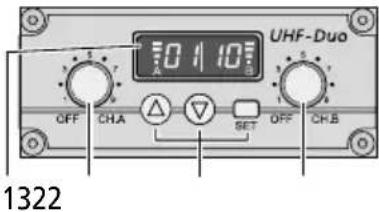
1.1 Receiver module
1 Display: indicates the transmission channel and the strength of the radio signal received (left: receiver unit A, right: receiver unit B)
2 Power switch and volume control, for receiver unit A and receiver unit B
3 Buttons to set the receiver module: chapter b.
1.2 Amplifier
4 Input MIC/LINE IN (combined XLR/6.3 mm jack):
XLR jack for a microphone or
6.3 mm jack for an audio unit with line output (e.g. MP3/CD player, radio)
5 Volume control LEVEL for the input MIC/LINE IN (4)
6 Volume control WIRELESS MIC for wireless microphones
7 Equalizer controls BASS, MIDDLE and TREBLE for the input MIC/LINE IN (4) and for the wireless microphones
8 Battery status LEDs for the internal rechargeable battery
CHARGE red = battery is being charged green = charging completed
FULL The battery has been fully charged. OK The battery is still sufficiently charged. LOW The battery is almost discharged.
9 Input jacks LINE IN (RCA) to connect an audio unit with line output
10 RCA jacks MIX OUT/LINE LINK to route the mixed signal to another active speaker system
11 Volume control LEVEL for the input LINE IN (9)
12 Tone controls BASS and TREBLE for the input LINE IN (9)
13 Switch for volume attenuation of the signal at the jacks LINE IN (9) during microphone announcements
LONG After an announcement, the attenuation will be deactivated with a delay.
OFFnoattenuation
SHORT After an announcement, the attenuation will be deactivated immediately.
14 Control DEPTH for the level of volume attenuation
15 Power LED PWR ON
16 POWER switch
Note: The battery will be charged even when the unit has been switched off.
17 LED LIMITER; lights up when the limiter limits the volume at the maximum undistorted level
18 Connection EXTERNAL SPEAKER for a 4 Ω speaker system (e. g. TXB-602 / SW) alternatively to or in parallel with the internal speakers
19 On / off switch INTERNAL SPEAKER for the integrated speakers
20 Mains jack for connection to a socket (230 V / 50 Hz) via the connection cable provided
21 Support for the mains fuse
Always replace a blown fuse by one of the same type!
2 Safety Notes
The unit corresponds to all relevant directives of the EU and is therefore marked with €€.
WARNING
The active speaker system uses dangerous mains voltage. Leave servicing to skilled personnel; inexpert handling may result in electric shock.
- The unit is suitable for indoor use only. Protect it against dripping water, splash water and high air humidity. The admissible ambient temperature range is 0–40°C.
- Do not place any vessels filled with liquid, e. g. drinking glasses, on the unit.
-
Immediately disconnect the mains plug from the socket
-
if the unit or the mains cable is visibly damaged,
- if a defect might have occurred after the unit was dropped or suffered a similar accident,
- if malfunctions occur.
In any case the unit must be repaired by skilled personnel.
- Never pull the mains cable to disconnect the mains plug from the socket, always seize the plug.
- For cleaning only use a dry, soft cloth; never use chemicals or water.
- No guarantee claims for the unit and no liability for any resulting personal damage or material damage will be accepted if the unit is used for other purposes than originally intended, if it is not correctly connected or operated, or if it is not repaired in an expert way.

If the unit is to be put out of operation definitively, take it to a local recycling plant for a disposal which is not harmful to the environment.
3 Applications and Accessories
The 2-way bass-reflex speaker system TXA-604 / SW with integrated 50 W amplifier is used for monophonic sound applications at lectures and other events. The amplifier is equipped with a receiver module for two wireless microphones and two inputs for audio units and a microphone.
For mains-independent operation, an integrated rechargeable battery is provided. This battery will be charged as soon as the active speaker system is connected to the mains. Thus, the unit is ideally suited for mobile applications.
The jacks LINE LINK (10) can be used to interconnect multiple active speaker systems for sound applications in large zones. A passive 4 Ω speaker system can also be operated in parallel (e.g. the model TXB-602 / SW with a matching design).
3.1 Wireless microphones and transmitters
The following units are available from MONACOR:
| Type Model | |
| Hand-held wireless microphone | TXA-800HT |
| Pocket transmitter with tie clip microphone and headband microphone | TXA-800HSE |
| Transmitter with line level input for audio signals | TXA-800ST |
3.2 Conformity and approval
Herewith, MONACOR INTERNATIONAL declare that the active speaker system TXA-604/ SW complies with the directive 2014 / 53 / EU. The EU declaration of conformity is available on the Internet:
www.monacor.com
The active speaker system is generally approved for operation in EU and EFTA countries; it is licence-free and requires no registration.
4 Setting into Operation
4.1 Setting up the active speaker system
Place the active speaker system as desired or mount it onto a PA speaker stand (e. g. PAST series from MONACOR) via the stand sleeve on its lower side.
The unit can be operated inside its transport bag: Unzip the zip fasteners of the flaps covering the speakers, the connections and the operating elements. Fold up the flaps and secure them with hook-and-loop fasteners.
4.2 Power supply
The speaker system is supplied with power via the integrated battery which is charged via the internal charger.
1) To charge the battery, connect the mains cable provided to the mains jack (20) and connect the mains plug to a socket (230 V/50 Hz).
2) The LED CHARGE (8) lights up: red = the battery is being charged
green = the charging process has been completed
The unit may be operated while its battery is charged; however, as long as the red LED LOW lights up, the full power is not available. To reduce the charging time, switch off the unit with the POWER switch (16).
3) When the battery has been fully charged, the LED CHARGE lights up in green. At maximum volume, a mains-independent operating time of up to 10 hours will be possible. A lower volume will extend the operating time.
4) Recharge the battery when the red LED LOW lights up.
Important!
Always disconnect the mains plug from the socket when the battery has been fully charged (LED CHARGE lights up in green) and the unit is not operated; otherwise, the battery may be damaged.
4.3 Connecting the active speaker system
| Unit Connection to jack | |
| Microphone with XLR plug | MIC/LINE(4) |
| Audio units with line output, e. g.: mixer, MP3/CDplayer, radio, microphone preamplifier | LINE IN (9) and with 6.3 mm plug to MIC / LINE (4) if no microphone is connected |
| Active speaker system | LINE LINK (10)If a second speaker system TXA-604/SW is used, connect its input LINE IN to the output LINE LINK of the first speaker system. |
| Passive speaker system EX | TERNAL SPEAKER (18) |
5 Operation
| Function Operating element | ||
| 1. | Switching the unit on/off | switch POWER (16) |
| 2. | Switching the internal speaker on/off | switch INTERNAL SPEAKER (19) |
| 3. | Volume for a microphone or audio unit connected to the jack MIC/LINE (4) | control LEVEL (5) |
| 4. | Volume for one or two wireless microphones | control WIRELESS MIC (6) |
| 5. | Sound for all microphones and an audio unit connected to the jack MIC/LINE (4) | controls BASS, MIDDLE and TREBLE (7) |
| 6. | Volume for an audio unit connected to the jack LINE IN (9) | control LEVEL (11) |
| 7. | Sound for an audio unit connected to the jack LINE IN (9) | controls BASS and TREBLE (12) |
Hint: To save battery power, always remember to switch off the wireless microphones after operation.
5.1 Operation of the receiver module
Each receiver unit (A and B) provides a control (2) to adjust the volume and to switch it on and off. The display (1) is divided into two parts: left half for receiver unit A, right half for receiver unit B. When a receiver unit has been switched on, the display will indicate the transmission channel. To briefly indicate the radio frequency, press the button (for unit A) or (for unit B).
5.1.1 Setting the transmission channels
Use the controls (2) to switch on the receiver units. Do not switch on the corresponding transmitter for the time being.
Channel scan
Keep the buttons and (3) simultaneously pressed for approx. 1 second until appears on the display. The scan will start: The receiver units will be set to free channels without mutual interference. If no free channels are found, the channels set will be kept.
Manual channel selection
If both receiver units A and B are switched on:
1) Keep the button SET (3) pressed until the channel indication for receiver unit A starts flashing on the display.
2) Select the channel for receiver unit A with the button or and then confirm with the button SET.
3) The channel indication for receiver unit B starts flashing on the display. Select the channel for receiver unit B with the button or and then confirm with the button SET.
If only one receiver unit A or B is switched on: Keep the button SET pressed until the channel indication starts flashing on the display. Select the channel with the button or and then confirm with the button SET.
Notes:
- The receiver units cannot be set to the same channel.
- If a channel is not confirmed within 10 seconds with the button SET, the setting mode will be exited and the channel previously set will be kept.
- If, with the transmitter switched off, the respective segment bar A or B on the display indicates reception, interference signals or signals from other transmitters are being received. In this case, select a different channel.
5.1.2 Adjusting the volume
Switch the transmitters on and set them to the channel of receiver unit A and receiver unit B respectively. The respective segment bars on the display will then indicate the strength of the radio signals received. Use the controls (2) to adjust the desired volume for each receiver unit.
5.1.3 Setting the squelch
The squelch function will mute the respective receiver unit when the level of the radio signal falls below the threshold value adjusted. Thus, interference signals will not cause noise when the transmitter is switched off or when its radio signal is insufficient: If the levels of the interference signals are below the threshold value, the receiver unit will be muted. A high threshold value offers high interference resistance, but it will also reduce the transmission range.
1) Switch off the receiver units A and B. Then keep the button SET (3) pressed while switching on a receiver unit. The display will indicate F1 or F2 with the number flashing.
2) Press the button SET to activate the squelch setting mode: 59 for "Squelch") and the current value (flashing) will appear on the display.
3) Use the button or to set the value (level 7 = highest threshold value). Press the button SET to exit the squelch setting mode.
Note: The setting modes will be automatically exited after 5 seconds if no button is pressed. Any settings made will be saved.
5.2 Limiter
The red LED LIMITER (17) lights up when the limiter limits the volume at the maximum undistorted level. If the LED lights permanently, use the control LEVEL (5 or 11) to reduce the volume.
5.3 Volume attenuation during microphone announcements
During microphone announcements, the volume of the audio unit connected to the jack LINE IN (9) can be attenuated automatically. This will make it easier to understand announcements.
1) Use the switch MUSIC RETURN TIME (13) to attenuate the volume:
LONG After an announcement, the attenuation will be deactivated with a delay.
OFF no attenuation
SHORT After an announcement, the attenuation will be deactivated immediately.
2) Use the control DEPTH (14) to adjust the level of attenuation. When the control is set to the left stop, the volume will not be attenuated. When the volume is attenuated during an announcement, the green LED on the left of the control will light up.
6 Specifications
Receiver module
Receiver units: .....2
Reception range: ..... 30 m approx.
Received frequencies
| Channel Frequency Channel | Frequency | |
| 01 863.1 MHz 09 863.2 | MHz | |
| 02 864.1 MHz 10 864.2 | MHz | |
| 03 863.6 MHz 11 863.7 | MHz | |
| 04 864.6 MHz 12 864.7 | MHz | |
| 05 863.3 MHz 13 863.4 | MHz | |
| 06 864.3 MHz 14 864.4 | MHz | |
| 07 863.8 MHz 15 863.9 | MHz | |
| 08 864.8 MHz 16 864.9 | MHz |
Amplifier
Rated power: .....50W
Music power: .....75W
Type: ....... mono, class D
Speakers
Bass speaker: .....20 cm (8")
Tweeter:....25 mm (1") horn tweeter
Audio frequency range: . . . 50–18 500 Hz
Inputs
MIC/LINE
XLR jack: ....for microphones, input sensitivity: 4.5 mV
6.3 mm jack: .....for audio units, input sensitivity: 30 mV
LINE IN (RCA jacks): . . . .for audio units, input sensitivity: 200 mV
Equalizer controls
BASS:....±12 dB at 55 Hz
MIDDLE: .... ±6 dB at 1 kHz
TREBLE: .... ±8 dB at 10 kHz
Power supply: .....230V, 50 Hz
Power consumption: .... 60VA max.
Battery type: ....rechargeable lead gel battery, 12V, 7.2Ah
Ambient temperature: ....0–40°C
Dimensions (W × H × D): .235 × 450 × 280 mm
Weight: 9.7 kg
Subject to technical modification.
All rights reserved by MONACOR® INTERNATIONAL GmbH & Co. KG. No part of this instruction manual may be reproduced in any form or by any means for any commercial use.
Table des matières
1 Vue d'ensemble 16
Grave :....20 cm (8")
Aigu :....pavillon aigu 25 mm (1")
BASS (graves): .....±12 dB à 55 Hz