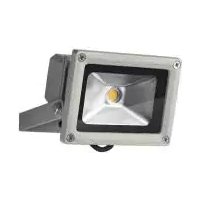
LSL 10 A1 - LED Spotlight Livarno Lux - Free user manual and instructions
Find the device manual for free LSL 10 A1 Livarno Lux in PDF.



| Product type | Outdoor LED spotlight with motion detector |
| Brand | Livarno Lux |
| Model | LSL 10 A1 |
| Rated voltage | 100 - 240 V ~ 50/60 Hz |
| Rated power | 20 W |
| Power factor | ≥ 0,7 |
| Protection class | I |
| Protection rating | IP 65 (dust-tight and protected against water jets) |
| Luminous flux | ≥ 1400 lumens |
| Color temperature | Approximately 6500 K (daylight) |
| Detection angle | 180° |
| Detector range | 8 - 10 m |
| Dimensions (L × W × H) | 18 × 19 × 10 cm (total height with bracket: 22,5 cm) |
| Net weight | 1055 g (1100 g with ground spike) |
| Package contents | Spotlight, wall bracket, screws and wall plugs, ground spike, instruction manual |
| Usage | Indoor and outdoor, wall mounting or on ground spike |
| Settings | Sensitivity (SENS), lighting duration (TIME) from 5 s to 8 min, light sensitivity (LUX) |
| Orientation | Spotlight adjustable vertically; detector adjustable horizontally and vertically |
| Maintenance | Clean with a dry, lint-free cloth; disconnect power before |
| Warranty | 3 years from date of purchase |
Frequently Asked Questions - LSL 10 A1 Livarno Lux
User questions about LSL 10 A1 Livarno Lux
0 question about this device. Answer the ones you know or ask your own.
Ask a new question about this device
Download the instructions for your LED Spotlight in PDF format for free! Find your manual LSL 10 A1 - Livarno Lux and take your electronic device back in hand. On this page are published all the documents necessary for the use of your device. LSL 10 A1 by Livarno Lux.
USER MANUAL LSL 10 A1 Livarno Lux
PROJECTEUR A LED LSL 20 A1
FR
PROJECTEUR A LED
Operation and Safety Notes
IAN101130

FR
Before reading, unfold the page containing the illustrations and familiarise yourself with all functions of the device.
GB Operation and Safety Notes Page 21

A
B

C


Introduction
Montage mural (ill. C / I)
2006/95/CE Directive Basse tension
EXPLOSIONSGEFAHR! Verwen
Intended use. Page 22
Parts description Page 22
Technical Data Page 22
Scope of delivery. 22
Safety notices.. Page 22
Preparation
Required tools.. Page 24
Prior to installation
Installation
Start-up
Aligning the motion detector . Page 25
Automatic operation.. Page 25
Cleaning and Care
Disposal
Guarantee and Service
Warranty Declaration. Page 26
Service address.. Page 26
Declaration of conformity
LED Spotlight
Introduction
Congratulations on your new product. You have selected a high quality product. Familiarise yourself with the product
before using it for the first time. In addition, please carefully refer to the operating instructions and the safety advice below. Only use the product as described and for the indicated purpose. You should keep these instructions. If you pass the product on to anyone else, please ensure that you also pass on all the documentation with it.
- Intended use
This spotlight is suitable for indoor and outdoor use. The light can be fastened to any normally inflammable surface. Do not use the light in water. Only have the installation performed by an authorised electrician. Any use other than that described above or any modification of the product is not permissible and will result in damage. The manufacturer is not liable for damage caused by improper use. The product is not intended for commercial use.
Parts description
Screw (cable terminal box)
Cable terminal box
3 Wall bracket
4 Adjusting screw (mounting bracket)
5 Locking screw (motion detector)
6 Rotary control SENS (sensitivity)
7 Rotary control TIME (switched on duration)
8 Rotary control LUX (light sensitivity)
9 Motion detector
10 Lightbulb
11 Ground stake
12 Brown cable
13 Green and yellow cable
14 Blue cable
15 Transformer (do not touch!)
Technical Data
Rated voltage: 100 - 240V 50 / 60Hz
Rated power: 20W
Power factor: >0.7
Protection class: I/

Protection class: IP 65 (dust- and splash-proof)
Detection angle: 180°
Luminous flux: >1400 lumen
Colour temperature: approx. 6500 Kelvin
Dimensions: 18 × 19 × 10cm (22.5 cm
incl. mounting bracket height)
Weight: 1100 g incl. ground spike,
1055 g net weight
Model no.: LSL 20 A1
Scope of delivery
1 LED Spotlight
2 Self-tapping screws M6 (for wall mounting)
2 Washers (0 8 mm)
2 Rawlplugs (for wall mounting)
1 Ground spike (for ground mounting)
1 Instructions for use

Safety notices
Damage due to failure to comply with these operating instructions will invalidate the guarantee! We assume no liability for consequential damage! We assume no liability for material damage or personal injury due to improper handling or failure to comply with the safety instructions!

DANGER TO LIFE AND ACCIDENT HAZARD FOR TODDLERS AND SMALL CHILDREN! Never
leave children unattended with the packaging material. The packaging material represents a danger of suffocation. Children frequently underestimate the dangers. Please keep children away from the product at all times.
This appliance may be used by children age 8 years and up, as well as by persons with re
duced physical, sensory or mental capacities, or lacking experience and / or knowledge, so long as they are supervised or instructed in the safe use of the appliance and understand the associated risks.
Never allow children to play with this device. Cleaning and user maintenance should not be performed by children without supervision.
DANGER TO LIFE! During installation keep children away from the area in which you are working. A large number of screws and other small parts are included with delivery. These may prove life-threatening if swallowed or inhaled.

EXPLOSION HAZARD! Do not
operate the light in potentially explosive environments containing flam
mable vapours, gases or dusts.
Do not expose the light to direct sunlight, rain, snow or ice. The product may otherwise be damaged.
The light may be mounted to any normally inflammable surfaces.

Avoid the risk of fatal injury from electric shock
Ensure that a qualified electrician, or a person trained to carry out electrical installations, performs the electrical installation.
Never use the light if any defects have been identified.
In the event of damage, repairs or other problems with the light, please contact the service centre or an electrician.
Never open any of the components of the electrical equipment or insert any objects into the same components. This will pose a risk of fatal injury from electric shock.
Prior to installation, remove the fuse or switch off the circuit breaker 0 setting in the fuse box.
Prior to installation verify the mains voltage on site corresponds with the operating voltage required for the light (100-240 V~).
Be careful not to damage lines during installation.

Prevent fire and injury hazards
■ RISK OF INJURY! Check every bulb and lampshade for damage immediately upon unpacking. Do not fit the light if the bulbs and / or lampshades are faulty. In this case contact the service centre for a replacement.
DANGER OF ELECTRIC SHOCK! DANGER OF DAMAGE TO PROPERTY! RISK OF INJURY! Please be sure not to drill into any electrical wiring, gas or water lines inside the wall. If necessary, use a cable detector before drill into the wall.
RISK OF BURNS! Ensure the light has been switched off and has cooled before touching it to avoid burns. Lights develop a lot of heat in the area of the lamp head.
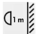
FIRE HAZARD! Fit the light so that it is at least 1 m away from the material to be illuminated. Excessive heat in a fire.
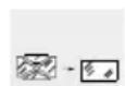
Broken glass must be replaced before using the light again.
The bulbs cannot be replaced.
Do not look directly into the light source (light bulb, LED etc.).
To prevent burns, verify the light is switched off and has cooled down for at least 15 minutes before touching it.

Safe working
Carefully prepare for assembly and allow yourself adequate time. Organise all parts and any necessary additional tools or materials before starting so they are easy to reach.
Always be attentive! Always pay attention to what you are doing and proceed with caution at all times. Never install the light if you are having difficulty concentrating or do not feel well.
Preparation
Required tools
The tools and materials specified are not included. This information and these values are non-binding and are only provided as a reference. The nature of the material is determined by the individual local conditions.
- Pencil/making tool
Voltage tester - Screwdriver
- Electric drill
- Drill bit
- Screws for wall mounting
- Rawlplugs
- Side cutting pliers
- Ladder
Prior to installation
Important: The electrical connection must be established by a qualified electrician or a person trained to perform electrical installations. This person must be familiar with the properties of the light and the connection regulations.
Familiarise yourself with all the instructions and diagrams in this manual, as well as with the light itself, before you install it.
Before installation ensure that the circuit, to which the light will be connected, is not energised. To do so, remove the fuse or switch off the circuit breaker in the fuse box 0 position.
Use the voltage tester to verify the de-energised status.
When selecting the mounting location, pay attention to the following:
Ensure the area you wish to light will be lit. The LED spotlight can be adjusted vertically.
Be sure the motion detects covers the desired area.
Be sure the motion detect is not impacted by other light sources at night, e.g. yard or street lighting, as this could impair the function.
Installation
Wall mounting (Fig. C / I)
Prior to installation, remove the fuse or switch off the circuit breaker 0 setting in the fuse box.
Hold the wall bracket against the wall in the location you wish to mount it and mark the drill holes on the wall using the predrilled holes in the wall bracket 3. If necessary, use a spirit level.
Note: Mount the light at a height of approx.
2.5 m to guarantee full functionality of the motion detector.
CAUTION! RISK OF INJURY! Please refer to the operating instructions of your electric drill.
Now drill the mounting holes ( 8mm) .Be careful not to damage the supply line.
Insert the rawlplugs into the bores.
Insert the self-tapping screws (M6) into the washers ( 8mm)
- Secure the wall bracket to the wall using the self-tapping screws.
Note: If the mounting position is higher than 3m use an additional self-tapping screw and washer (not included).
After mounting, verify the wall bracket is securely fitted.
Open the cable terminal box by loosening the four screws 1.
Now insert the 3-wire lead through the cable gland and into the cable terminal box 2.
Connect the cab, 13, 14 with the terminals by adjusting their screws inside the cable terminal box (Fig. B).
Connect the mains cable by securing the nut on the cable gland until the cable terminal box 2 is watertight.
Close the cable terminal box using the four screws until it is watertight.
Replace the fuse or switch on the circuit breaker in the circuit breaker box.
Ground Mounting (Fig. C / II)
Open the cable terminal box by loosening the four screws 1.
Now insert the 3-wire lead through the cable gland and into the cable terminal box 2.
Connect the cable 2 13,14 with the terminals by adjusting their screws inside the cable terminal box 2 (Fig.B).
Connect the mains cable by securing the nut on the cable gland until the cable terminal box 2 is watertight.
Close the cable terminal b using the four screws until it is watertight.
Screw the ground spike into the centre hole on the wall bracket 3.
Insert the LED spotlight with ground spike far enough into the ground (lawn, flower bed) so it is firmly seated. Make sure it is firmly placed. Do not use any force when assembling or setting up the product, e.g. hammer blows. This damages the product.
The light is now ready for operation.
Notice:
If the lighting angle is not ideal, switch the light off and allow to cool down for 15 minutes. Loosen the adjusting screws with a screwdriver and readjust the lighting angle. Then tighten the adjusting screws.
Start-up
Note: The LED Spotlight features a motion detector 9 which responds to temperature changes. The motion detector 9 works best in ambient temperatures below 20° . A moving object with a temperature near the ambient temperature is difficult to detect.
Note: The control dials are located below the motion detector (Fig. A).
Note: The range of the motion detector is approx. 8 - 10m , the detection radius is approx. 180° .
Aligning the motion detector
Note: The detection area must be well within range of the infrared beams from the motion detector 9. The view of the detection area must not be obstructed by objects such as plants etc. Infrared beams cannot pass through solid objects.
Note: The detection area should run transversely to the direction of passage and be kept as small as possible. A large detection area increases the risk of the light being switched on for irrelevant reasons.
- First align the motion detector 9 horizontally.
- Then loosen the locking screw (motion detector) 5 by turning it counter-clockwise.
- Now align the motion detector 9 vertically and tighten the locking screw (motion detector) 5 clockwise.
- Test your settings by walking slowly into the detection area. Repeat steps 1 to 3 until you achieve the desired result.
Automatic operation
Adjusting the sensor sensitivity (SENS):
Adjust the sensor sensitivity to your preferences using the SENS rotary control 6.
Turn clockwise to increase the sensor sensitivity.
Turn counter-clockwise to decrease the sensor sensitivity.
Note: The further right the rotary control is turned, the more sensitive the motion detector will be, i.e. it will already respond to minor temperature changes within the detection range. If the sensitivity is set too high, even small animals or movement from leaves (from trees or shrubs) may already trigger the motion sensor, inadvertently activating the light.
Adjusting the on duration (TIME):
Set the light on time (5 s-8 min) using the TIME rotary control 7.
Turn clockwise to increase the on time. Turn counter-clockwise to decrease the on time.
Adjusting the light sensitivity (LUX):
Set the desired light sensitivity using the LUX rotary control 8.
Turn clockwise to increase the light sensitivity. The light is more sensitive to changes in light intensity and switches to automatic mode sooner.
Turn counter-clockwise to decrease the light sensitivity. The light is less sensitive to changes
.../Cleaning .../Disposal/Guarantee and Service/Declaration of conformity
in light intensity and takes longer to switch to automatic mode.
Note: If the LUX rotary control 8 is in the position, the motion detector will work day and night. If the LUX rotary control 8 is in the position, the motion detector will only work at night.
Note: Once the light has been activated by the motion detector 9, it will remain on for the set time. If new movement is detected during this time, the original period will be extended by this set amount of time.
- Cleaning and Care
CAUTION! RISK OF ELECTRIC SHOCK!
Disconnect the light from the mains circuit before cleaning. To do so, remove the fuse or switch off the circuit breaker in the fuse box 0 position.
Do not use solvents, petrol, etc. Otherwise the light will be damaged.
Allow the light to cool off completely.
Only use a dry, lint-free cloth for cleaning.
Disposal

The package and packaging materials consist entirely of environmentally friendly materials. They can be disposed of at your local recycling facility.

Do not dispose of electric equipment in the household waste!
In accordance with European Directive 2012 / 19 / E relating to old electrical and electronic appliances and its translation into national law, used electrical equipment must be collected separately and recycled in an ecologically compatible way.
Contact your local council to find about the current options for the disposal of discarded electrical equipment.
- Guarantee and Service
Warranty Declaration
This product has a 3 year guarantee from the date of purchase extended only to the original buyer, not transferable. Please keep your receipt as proof of purchase. The guarantee applies to material or manufacturing defects only. It does not cover wear items or damage caused by improper use. Any modifications will void the guarantee. This warranty does not limit your legal rights. Please phone the service centre for guarantee claims. This is the only way to return your product free of charge.
Service address
Atlanta Electronics GmbH
Gernotstr. 18
44319 Dortmund, Germany
E-Mail: info@atlanta-electronics.de
IAN 101130
Please have your receipt and the article number (e.g. IAN 12345) ready as your proof of purchase when enquiring about your product.
Declaration of conformity
The CE mark was applied in accordance with the following European directives.
The relevant documents have been archived and can be requested as necessary.
2006/95/EC Low Voltage Directive
2004/108/EC EMC Directive
2011/65/EC (RoHS II)
2009/125/EC EMC Directive
EMC C∈IP65


ATLANTA ELECTRONICS GMBH
Gernotstr. 18
44319 Dortmund


- PROJECTEUR A LED LSL 20 A1
- PROJECTEUR A LED
- FR
- INTRODUCTION
- MONTAGE MURAL (ILL. C / I)
- EXPLOSIONSGEFAHR! VERWEN
- SAFETY NOTICES.. PAGE 22
- PREPARATION
- PRIOR TO INSTALLATION
- INSTALLATION
- START-UP
- CLEANING AND CARE
- DISPOSAL
- GUARANTEE AND SERVICE
- DECLARATION OF CONFORMITY
- LED SPOTLIGHT
- INTENDED USE
- PARTS DESCRIPTION
- TECHNICAL DATA
- SCOPE OF DELIVERY
- SAFETY NOTICES
- DANGER TO LIFE AND ACCIDENT HAZARD FOR TODDLERS AND SMALL CHILDREN! NEVER
- EXPLOSION HAZARD! DO NOT
- AVOID THE RISK OF FATAL INJURY FROM ELECTRIC SHOCK
- PREVENT FIRE AND INJURY HAZARDS
- SAFE WORKING
- REQUIRED TOOLS
- WHEN SELECTING THE MOUNTING LOCATION, PAY ATTENTION TO THE FOLLOWING
- WALL MOUNTING (FIG. C / I)
- GROUND MOUNTING (FIG. C / II)
- NOTICE
- ALIGNING THE MOTION DETECTOR
- AUTOMATIC OPERATION
- ADJUSTING THE SENSOR SENSITIVITY (SENS)
- ADJUSTING THE ON DURATION (TIME)
- ADJUSTING THE LIGHT SENSITIVITY (LUX)
- CAUTION! RISK OF ELECTRIC SHOCK
- DO NOT DISPOSE OF ELECTRIC EQUIPMENT IN THE HOUSEHOLD WASTE
- WARRANTY DECLARATION
- SERVICE ADDRESS
- IAN 101130
- 2006/95/EC LOW VOLTAGE DIRECTIVE
- 2004/108/EC EMC DIRECTIVE
- 2011/65/EC (ROHS II)
- 2009/125/EC EMC DIRECTIVE
- EMC C∈IP65
Brand : Livarno Lux
Model : LSL 10 A1
Category : LED Spotlight