LP55278 - Counter hygiene protection Vollrath - Free user manual and instructions
Find the device manual for free LP55278 Vollrath in PDF.
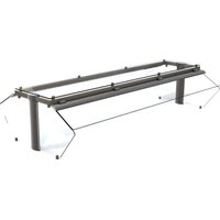
| Product Type | Articulated glass sneeze guard for buffet counter |
| Brand | Vollrath |
| Model | LP55278 |
| Use | Hygienic protection for counter, two-sided buffet, 3 compartments |
| Main material | Tempered glass, stainless steel uprights |
| Approximate dimensions | Length suitable for a 3-compartment counter (approx. 74 in / 188 cm) |
| Weight | Approximately 15-20 kg depending on configuration |
| Power supply | Not required for base sneeze guard; compatible with optional heating (120 V) and lighting |
| Main functions | Protection against droplets, separation of service areas, optimal visibility |
| Included components | Uprights, panels, gaskets, tie rods, nuts, drilling template, Allen key |
| Installation | Requires counter drilling, fixing with rods and nuts; two people recommended |
| Maintenance and cleaning | Clean with a soft cloth and non-abrasive cleaner; avoid harsh chemicals |
| Safety | Tempered glass resistant to impacts; NSF compliant gaskets and caps |
| Spare parts available | Gaskets, screws, caps, glass kits, optional heating/lighting ramps |
| Repairability | One-side conversion kit available; spare parts via Vollrath |
| Certifications | Compliant with NSF standards |
| Warranty | Standard manufacturer warranty (see manual) |
| Customer service | Vollrath: 800.628.0830 (USA); technical support: techservicereps@vollrathco.com |
| Compatibility | Signature Server® stainless steel counters or others with suitable preparation |
| Optional accessories | Heating ramp (no. 350752-350755); lighting ramp (no. 350744-350751) |
Frequently Asked Questions - LP55278 Vollrath
User questions about LP55278 Vollrath
0 question about this device. Answer the ones you know or ask your own.
Ask a new question about this device
Download the instructions for your Counter hygiene protection in PDF format for free! Find your manual LP55278 - Vollrath and take your electronic device back in hand. On this page are published all the documents necessary for the use of your device. LP55278 by Vollrath.
USER MANUAL LP55278 Vollrath
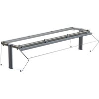
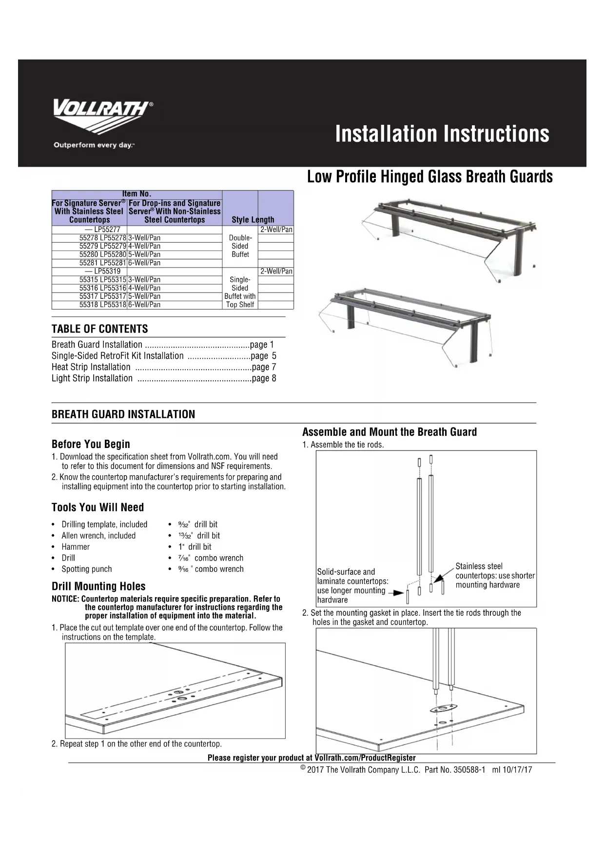
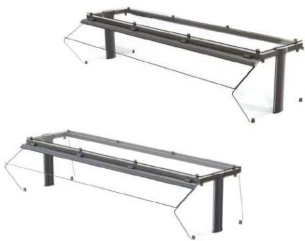
Low Profile Hinged Glass Breath Guards
| Item No. | Style Length | ||
| For Signature Server®With Stainless Steel Countertops | For Drop-ins and Signature Server®With Non-Stainless Steel Countertops | ||
| — LP55277 | Double-Sided Buffet | 2-Well/Pan | |
| 55278 LP55278 | 3-Well/Pan | ||
| 55279 LP55279 | 4-Well/Pan | ||
| 55280 LP55280 | 5-Well/Pan | ||
| 55281 LP55281 | 6-Well/Pan | ||
| — LP55319 | Single-Sided Buffet with Top Shelf | 2-Well/Pan | |
| 55315 LP55315 | 3-Well/Pan | ||
| 55316 LP55316 | 4-Well/Pan | ||
| 55317 LP55317 | 5-Well/Pan | ||
| 55318 LP55318 | 6-Well/Pan | ||
TABLE OF CONTENTS
Breath Guard Installation . page 1
Single-Sided RetroFit Kit Installation . page 5
Heat Strip Installation page 7
Light Strip Installation . page 8
BREATH GUARD INSTALLATION
Before You Begin
- Download the specification sheet from Vollrath.com. You will need to refer to this document for dimensions and NSF requirements.
- Know the countertop manufacturer's requirements for preparing and installing equipment into the countertop prior to starting installation.
Tools You Will Need
Drilling template, included drill bit
- Allen wrench, included 13132 drill bit
Hammer 1' drill bit
Drill 7/16* combo wrench
- Spotting punch
- 9 / 16 " combo wrench
Drill Mounting Holes
NOTICE: Countertop materials require specific preparation. Refer to the countertop manufacturer for instructions regarding the proper installation of equipment into the material.
- Place the cut out template over one end of the countertop. Follow the instructions on the template.
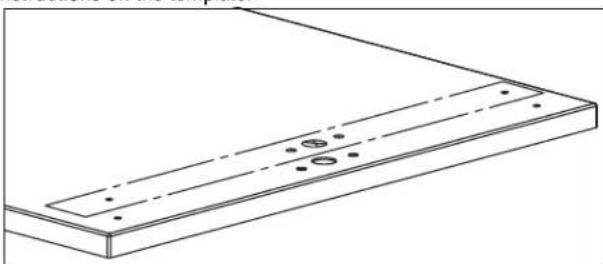
- Repeat step 1 on the other end of the countertop.
Assemble and Mount the Breath Guard
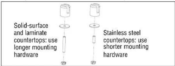
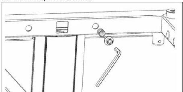
- Assemble the tie rods.
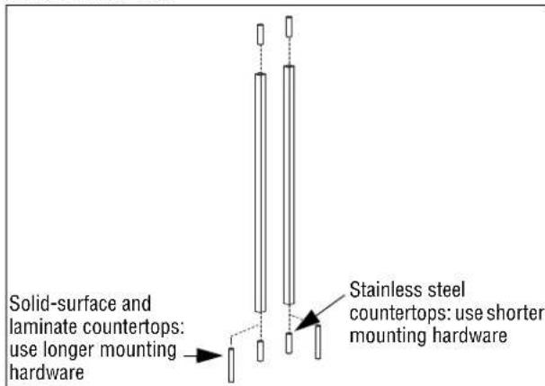
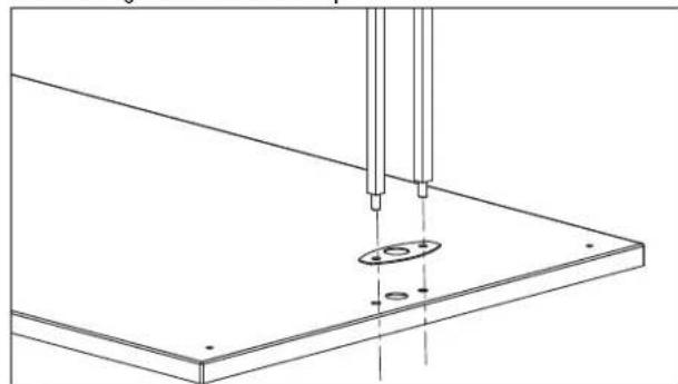
- Set the mounting gasket in place. Insert the tie rods through the holes in the gasket and countertop.
Please register your product at Vollrath.com/ProductRegister
BREATH GUARD INSTALLATION (CONTINUED)
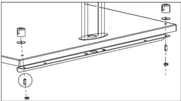
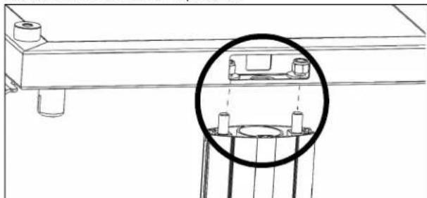
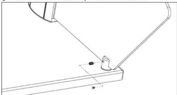
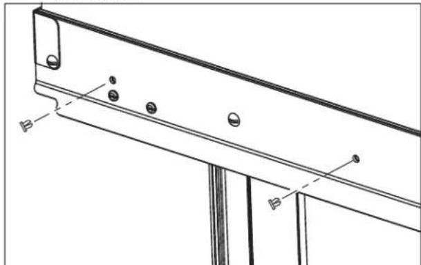
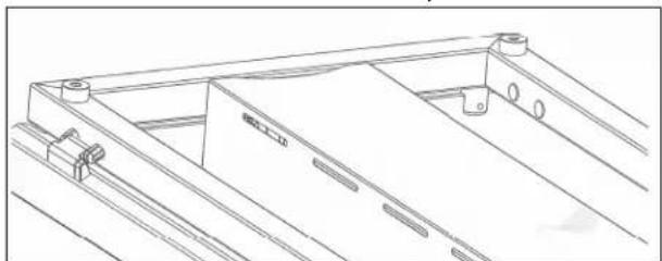
- Position the stiffening bracket on the underside of the countertop and over the tie rod extensions. Secure the tie rods to the base frame with the included nuts.
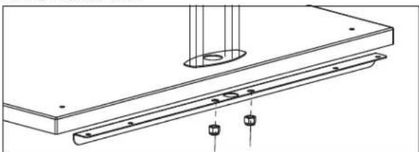
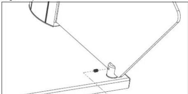
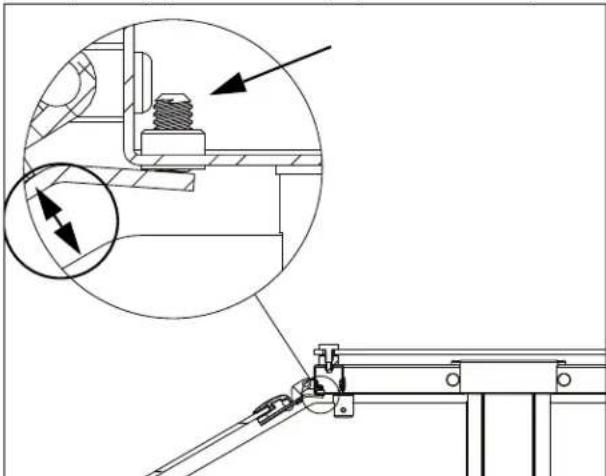
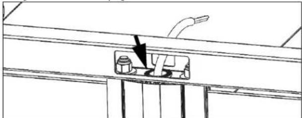
- Install the gaskets and standoffs to the countertop
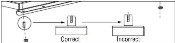
- Position the stud so it is flush with the bottom of the slot in the standoff.
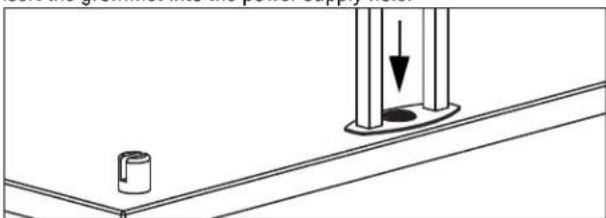
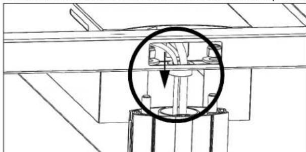
- Insert the grommet into the power supply hole.
-
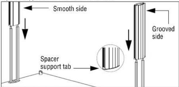
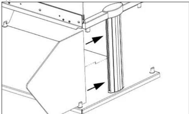
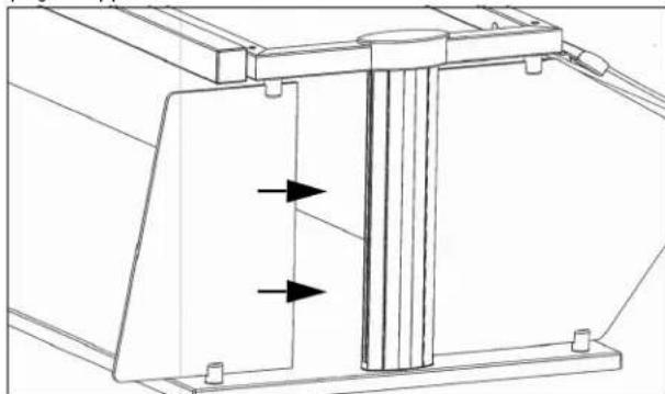
Slide the uprights over the tie rods:
-
Smooth side facing inward and the grooved side facing outward
- Spacer support tab must be at the bottom
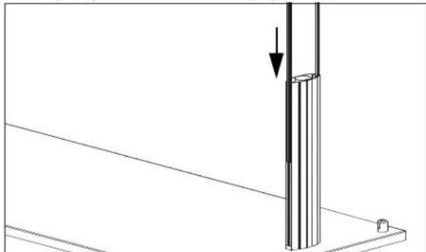
- Slide the glass gaskets into slots of the uprights.
If Your Breath Guard: Includes a heat strip and/or lights
- Thread the wires through the upright and into the cabinet below. Use the included washers and nuts to attach the tie rods to the top frame.
- If your breath includes a heat strip and/or lights, continue on page 7 with step 6.
11.If your breath guard contains only lights, continue below with step 13.
Does not include heat strips or lights
- Place the top frame over the uprights and thread the tie rods through the holes in the frame. Use the included washers and nuts to attach the tie rods to the top frame.
13.Install the end caps.
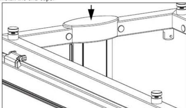
BREATH GUARD INSTALLATION (CONTINUED)
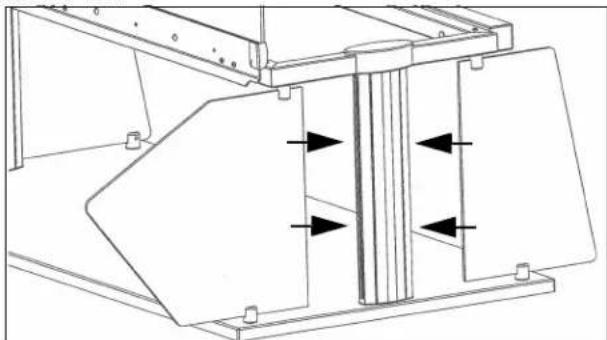
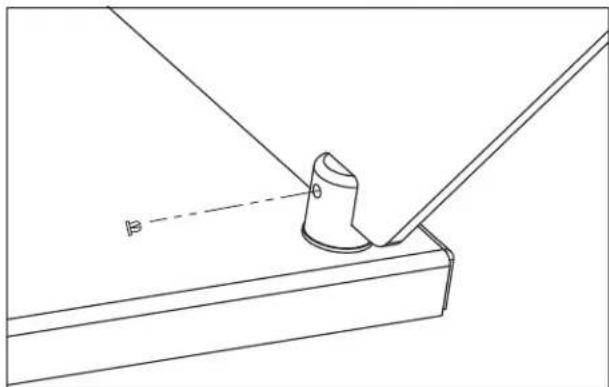
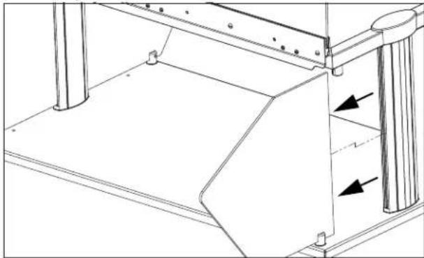
Install the Glass Panels Long Side Panel(s)
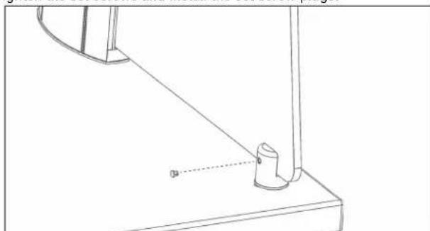
- Attach the gaskets to the square-cornered-side of the long-side glass panels.
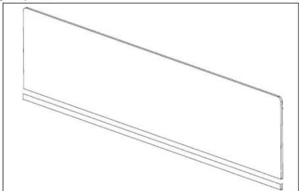
- Insert the gasket side of one long-side glass panel,
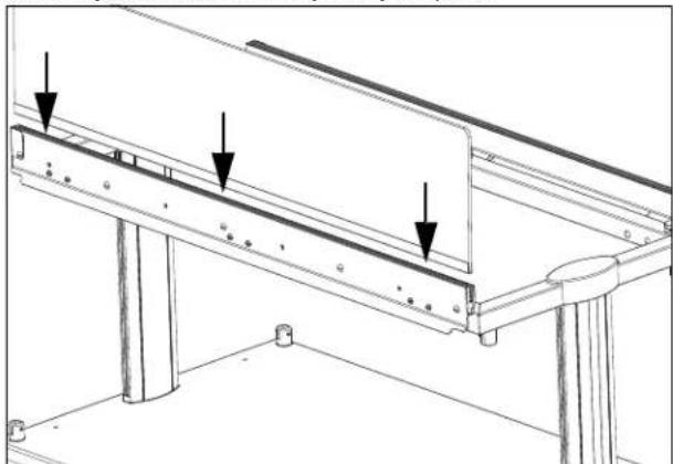
- Tighten the set screws to secure the glass in place.
- Repeat the steps for with long-side glass panel for the other side.
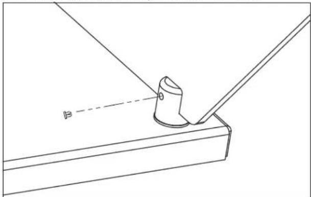
Short Side Panels
For Double Sided Breath Guards
- Insert one short-end glass panel into the gasket on the upright support.
- Tighten the sets screws on the top and bottom stand-offs.
- Repeat the steps for the other short-end panel.
For Single Sided Breath Guards
- Insert the wider end glass panel into the gasket on the upright support below the long side glass panel. Insert the narrow panel on the other side.
- Tighten the sets screws on the top and bottom stand-offs to secure the glass in place.
- Repeat for the other end.
BREATH GUARD INSTALLATION (CONTINUED)
Install the Glass Panels (Continued)
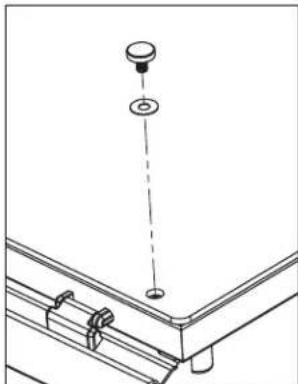
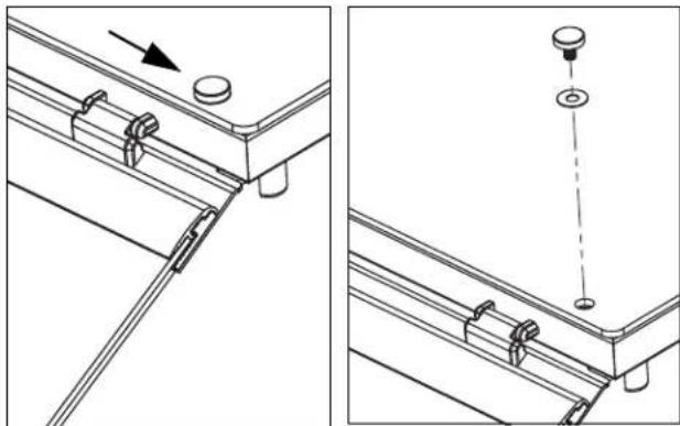
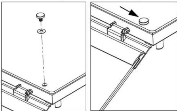
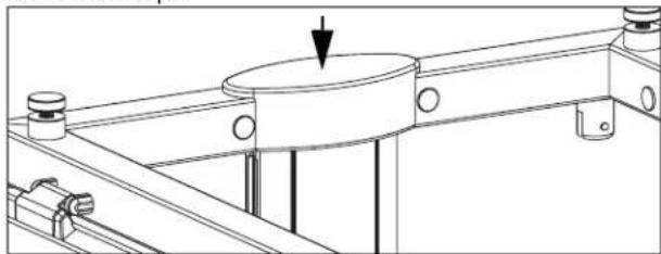
Top Panel
- Remove the caps from the stand-offs on the top of the breath guard.
- Set the top glass into place. Align the holes in the glass with the holes on the standoffs.
- Thread the vinyl washers onto the caps and insert into the holes. Tighten the caps. Do not over tighten.
- Adjust the set screws on both ends of the hinged glass panel to create a parallel gap between the hinged panel and the end glass.
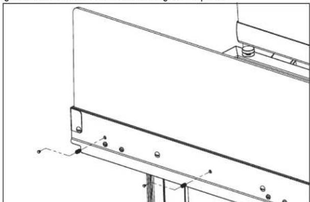
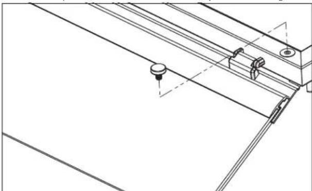
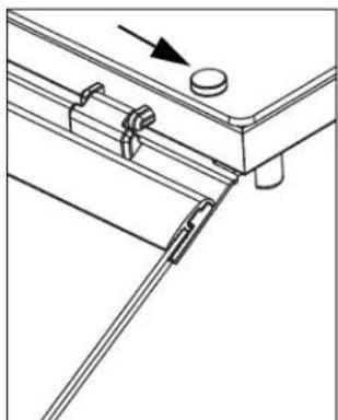
Install the Cover Plugs
- Insert a cover plug over each set screw in the glass mounting bracket and stand-offs.
NOTICE: Set screw covers plugs must be inserted to meet NSF certification.
SINGLE-SIDED RETROFIT KIT INSTALLATION
| Kit Item No. | Description | Kit Contents and Quantity | |||
| Ballast Bar | Narrow End Glass Panels | Mounting Bolts | Allen Wrenches | ||
| 350736 46" | 1 | 2 | 6 | 2 | |
| 350737 60" 6 | |||||
| 350738 74" 8 | |||||
| 350739 88" 8 | |||||
| 350740 2-Well 4 | |||||
| 350741 3-Well 6 | |||||
| 350742 4-Well 6 | |||||
| 350743 5-Well 8 | |||||
| 350744 6-Well 8 | |||||
Tools You Will Need
18 Allen wrench (supplied with breath guard)
% 山 Allen Wrench (supplied with breath guard)
- Standard Screwdriver
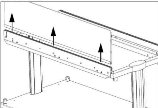
Remove the Top Glass
- Loosen and remove the stand-offs.
- Lift off the top glass.
Remove the End Panels
- Loosen the sets screws on the top and bottom stand-offs.
- Remove the glass.
Remove the Long Side Glass Panel
- Remove the cover plugs over the set screws in the glass mounting bracket.
- Loosen the set screws.
- Remove the glass.
SINGLE-SIDED RETROFIT KIT INSTALLATION (CONTINUED)
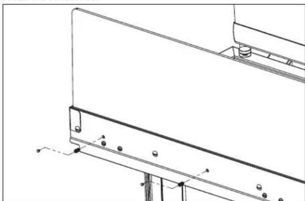
Remove the Mounting Bracket
- Remove the inner frame plugs. Save the plugs.
- Remove the hinge by removing the hinge assembly screws.
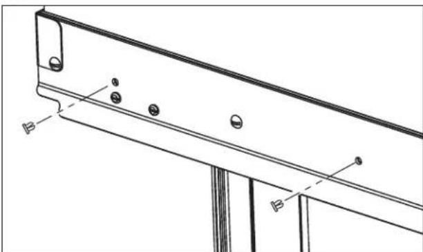
Install the Ballast Bar
- Attach the ballast bar using the included screws.
- Reinstall the frame plugs.
Install the End Glass
- Insert the included short-end glass panel into the gasket on the upright support.
- Tighten the set screws and install the set screw plugs.
- Repeat for the other end.
Reinstall the Top Glass
- Set the top glass into place. Align the holes on the glass with the holes on the stand-offs. Thread the vinyl washers onto the caps and insert into the holes. Tighten the caps. Do not over tighten.
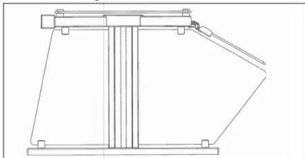
End Profile of Single Sided Breath Guard
HEAT STRIP INSTALLATION
| Kit Item No. | For Use Over |
| 350752 46' | |
| 350753 60' | |
| 350754 74' | |
| 350755 88' | |
| 350756 2 Well | |
| 350757 3 Well | |
| 350758 4 Well | |
| 350759 5 Well | |
| 350755 6 Well |
NOTICE: Heat strip connections must be performed by a licensed electrician.
NOTICE: Installation requires two people to lift the heat strip into place.
If this is a retrofit installation
Remove the upright caps and top glass before proceeding with the installation.
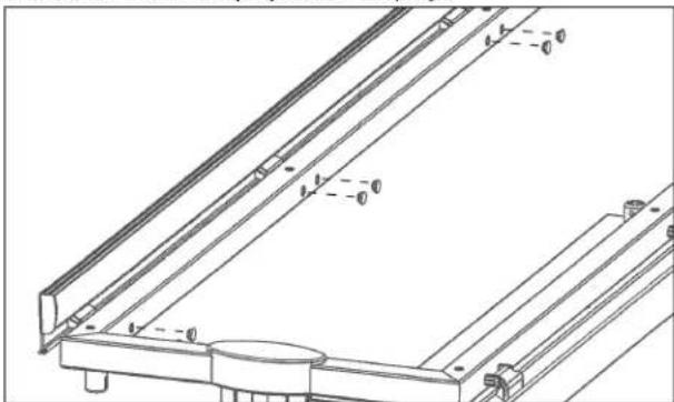
Installation
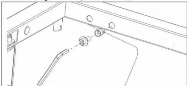
- Press the threaded inserts into frame holes next to the access hole. Install a bolt with a washer into an anchor. Tighten with the supplied allen wrench. Repeat for each hole.
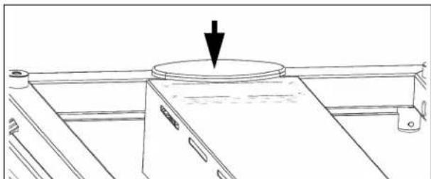
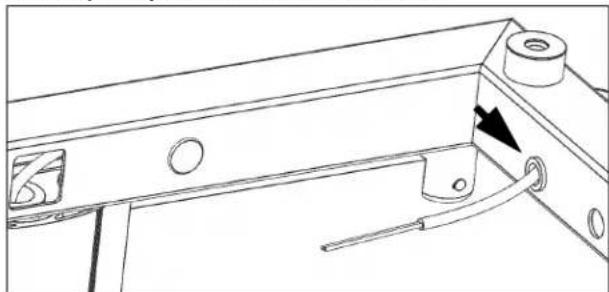
- Install the included large grommet into the frame hole on the power supply end. Pull the power supply wiring from the cabinet up through the hole in the upright.
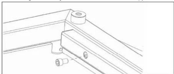
- With two people, lift up the heat strip assembly through the middle of frame until the shroud is flush with the top of frame.
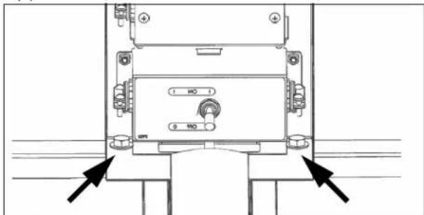
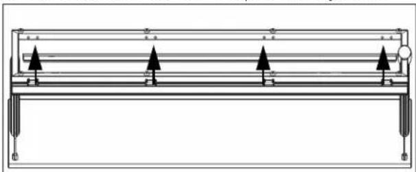
- Mount the heat strip by installing and tightening the four included hex bolts and washers through the ends of the shroud and into the threaded inserts. (Shown looking up at the underside of the heat strip.)
-
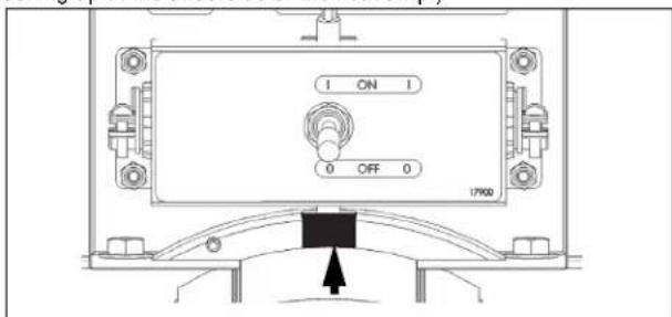
Wire the heat strip control box.
-
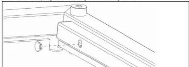
Attach the included rubber cord boot around the wire. The rounded side must face the top of the breath guard. Install the slotted end cap onto the frame and push the boot firmly into the slot. (Shown looking up at the underside of the heat strip.)
- Tighten the set screw until snug. (Shown looking up at the underside of the heat strip.)
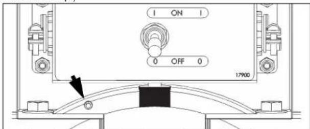
- Install the end cap without the slot onto the opposite end of the frame.
LIGHT STRIP INSTALLATION
| Kit Item No. | For Use With | Kit Item No. | For Use With |
| 350744 46' 350748 | 2 Well | ||
| 350745 60' 350749 | 3 Well | ||
| 350746 74' 350750 | 4 Well | ||
| 350747 88' 350751 | 5 Well | ||
| 350747 6 Well | |||
NOTICE: Light assembly connection must be performed by a licensed electrician.
If this is a retrofit installation
- Remove the upright caps and top glass before proceeding with the installation.
- Remove the frame plugs from the insides of the long sides of the top frame.
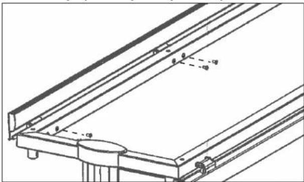
Installation
- Center and hold the light assembly up to the inside of the front or back frame tube. Mark holes that will require mounting anchor.
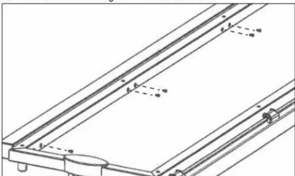
- Press the threaded inserts into the marked frame holes. Install a bolt with washer into an anchor and tighten with the supplied allen wrench until snug wrench. Repeat for each hole.
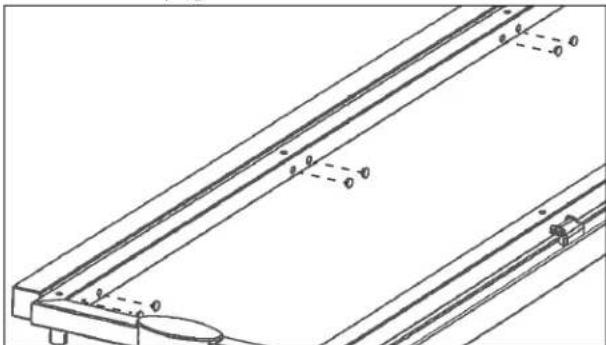
- Install the included large grommet into the frame hole on the power supply end. Pull the power supply wiring from the cabinet up through the hole in the upright.

- Install the included small grommet into the end frame hole nearest to the power supply. Pull the power supply wiring through the frame and through the grommet installed in the end hole.
-
Wire the light. Tuck the wire nuts into the back of the light assembly.
-
Attach the light assembly to the frame tube with the supplied bolts.
- Install the hole plugs into the light assembly holes.
- Install the end caps.

Outperform every day.
www.vollrath.com
The Vollrath Company, L.L.C.
1236 North 18th Street
Sheboygan.WI 53081-3201 U.S.A.
Main Tel: 800.624.2051 or 920.457.4851
Main Fax: 800.752.5620 or 920.459.6573
Customer Service: 800.628.0830
Canada Customer Service: 800.695.8560
Technical Services
techservicereps@vollrathco.com
Induction Products: 800.825.6036
Countertop Warming Products: 800.354.1970
Toasters: 1-800-309-2250
All Other Products: 800.628.0832
Outperform every day.
www.vollrath.com
The Vollrath Company, L.L.C.
1236 North 18th Street
Outperform every day.
www.vollrath.com
The Vollrath Company, L.L.C.
1236 North 18th Street