
ELPMBP05 - Projector EPSON - Free user manual and instructions
Find the device manual for free ELPMBP05 EPSON in PDF.
| Product Type | Ceiling mount for projector |
| Brand | Epson |
| Model | ELPMBP05 |
| Maximum load capacity | 113 kg (250 lb) |
| Plate material | Steel |
| Compatible column diameter | 38.1 mm (1½ in) NPT or NPSM (threading according to ANSI/ASME B1.20.1, Table 40) |
| Number of load cables | 4, with adjustable tensioners |
| Safety cable included | Yes, attaches to plate |
| Required tools | Phillips screwdriver, drill (for anchors), hammer |
| Supported ceiling types | Solid concrete, steel, wood (with appropriate anchors) |
| Installation | Above or in place of an existing ceiling tile |
| Compatible accessories | Poles ELPMBC02/03/04, ceiling plate ELPMBP07, projector mount ELPMBPRH |
| Warranty | 10 years (mechanical parts), 1 year (electrical components) |
| Use | Indoor only |
| Standards | Compliant with UL, ANSI/NFPA 70, CSA C22.1 |
Frequently Asked Questions - ELPMBP05 EPSON
User questions about ELPMBP05 EPSON
0 question about this device. Answer the ones you know or ask your own.
Ask a new question about this device
Download the instructions for your Projector in PDF format for free! Find your manual ELPMBP05 - EPSON and take your electronic device back in hand. On this page are published all the documents necessary for the use of your device. ELPMBP05 by EPSON.
USER MANUAL ELPMBP05 EPSON
INSTALLATION INSTRUCTIONS
natural_image
Technical line drawing of a structural frame assembly with hanging weights and supports (no text or symbols)Suspended Ceiling Tile Replacement Kit Trousse de remplacement de dalle de plafond suspendu Kit de reemplazo de panel de cielo raso suspendido Kit de substituição de placa de teto suspenso
ELPMBP05
LEGEND / LÉGENDE / REFERENCIAS / LEGENDA


Tighten Fastener
Phillips Screwdriver
Destornillador Phillips
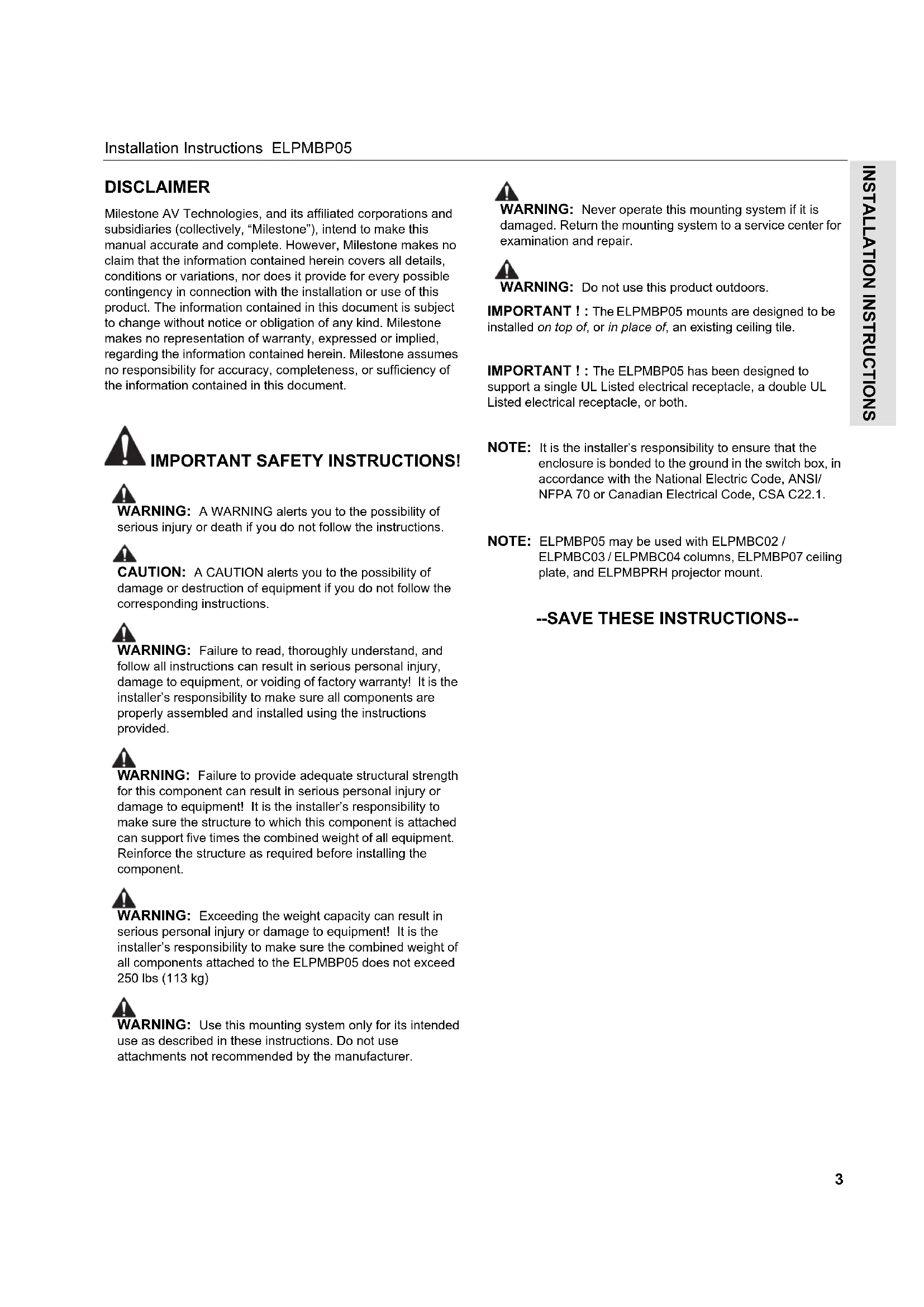
Milestone AV Technologies, and its affiliated corporations and subsidiaries (collectively, "Milestone"), intend to make this manual accurate and complete. However, Milestone makes no claim that the information contained herein covers all details, conditions or variations, nor does it provide for every possible contingency in connection with the installation or use of this product. The information contained in this document is subject to change without notice or obligation of any kind. Milestone makes no representation of warranty, expressed or implied, regarding the information contained herein. Milestone assumes no responsibility for accuracy, completeness, or sufficiency of the information contained in this document.

IMPORTANT SAFETY INSTRUCTIONS!

WARNING: A WARNING alerts you to the possibility of serious injury or death if you do not follow the instructions.

CAUTION: A CAUTION alerts you to the possibility of damage or destruction of equipment if you do not follow the corresponding instructions.

WARNING: Failure to read, thoroughly understand, and follow all instructions can result in serious personal injury, damage to equipment, or voiding of factory warranty! It is the installer's responsibility to make sure all components are properly assembled and installed using the instructions provided.

WARNING: Failure to provide adequate structural strength for this component can result in serious personal injury or damage to equipment! It is the installer's responsibility to make sure the structure to which this component is attached can support five times the combined weight of all equipment. Reinforce the structure as required before installing the component.

WARNING: Exceeding the weight capacity can result in serious personal injury or damage to equipment! It is the installer's responsibility to make sure the combined weight of all components attached to the ELPMBP05 does not exceed 250 lbs (113 kg)

WARNING: Use this mounting system only for its intended use as described in these instructions. Do not use attachments not recommended by the manufacturer.

WARNING: Never operate this mounting system if it is damaged. Return the mounting system to a service center for examination and repair.

WARNING: Do not use this product outdoors.
IMPORTANT ! : The ELPMBP05 mounts are designed to be installed on top of, or in place of, an existing ceiling tile.
IMPORTANT ! : The ELPMBP05 has been designed to support a single UL Listed electrical receptacle, a double UL Listed electrical receptacle, or both.
NOTE: It is the installer's responsibility to ensure that the enclosure is bonded to the ground in the switch box, in accordance with the National Electric Code, ANSI/NFPA 70 or Canadian Electrical Code, CSA C22.1.
NOTE: ELPMBP05 may be used with ELPMBC02 / ELPMBC03 / ELPMBC04 columns, ELPMBP07 ceiling plate, and ELPMBPRH projector mount.
--SAVE THESE INSTRUCTIONS--
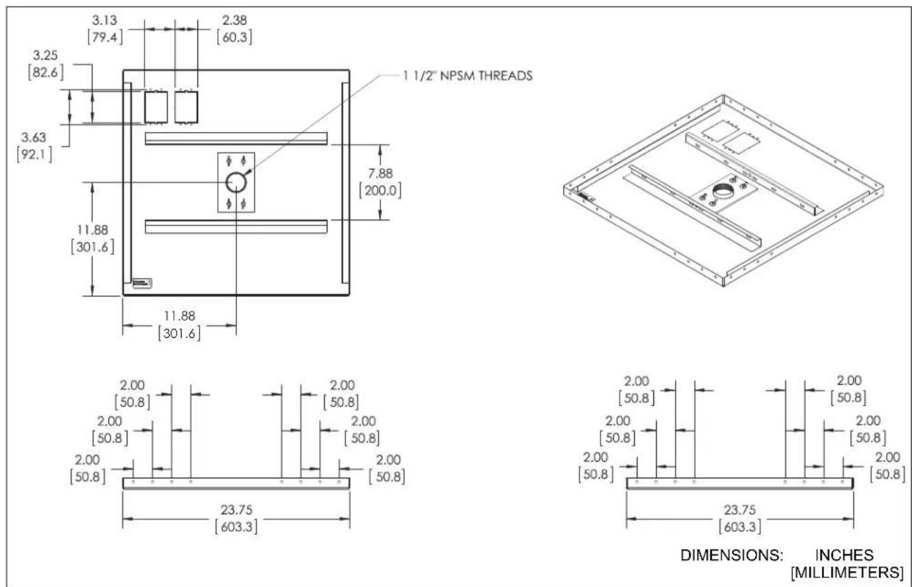
DIMENSIONS
TOOLS REQUIRED FOR INSTALLATION

PARTS
![A (1) [ELPMBP05 assembly] B (1) AWG #12 x 20ft [Support wire] C (1) 1/8" x 10ft [Safety cable] D (4) [Hanger bracket] E (4) [Ceiling framework clamp] F (4) 1/4" [Tumbuckle] G (2) [Wire clamp] H (4) 1/4" x 2" [Anchor] J (4) 0.262" x 1-5/16" [Eye lag] K (8) 1/4-20 x 3/8" L (4) 1/4-20 x 1" M (1) 10-24 x 1/4" N (1) 10-24 x 1/4" (security) P (1) [Locking collar] Q (1) 5/32" [security]](/content/2026/03/562739/images/1c7cd3c79d03e499b3d6fbd283316caa657ddb52f7b788a149acf8d34c338e53.jpg)
SITE PREPARATION / ASSEMBLY
NOTE: The ELPMBP05 may either be installed on top of, or in place of, an existing ceiling tile.
NOTE: The ELPMBP05 can accommodate one 1-1/2" NPT or NPSM following ANSI/ASME B1.20.1 (Schedule 40, 0.154" minimum thickness steel or aluminum - ASTM B221) threaded extension column (not included) located in center of assembly (See Figure 1). Threaded extension column must have a minimum of four threads engaged.

natural_image
Technical diagram of a ceiling-mounted air duct system with directional arrows indicating airflow or movement (no text or symbols present)Figure 1
-
Select the best mounting location based upon the following items (See Figure 2):
-
Dimensional offset of display/projector relative to column (due to mount and/or interface).
- For Projectors: Any recommended dimensions of projector relative to target (see installation instructions included with the projector).
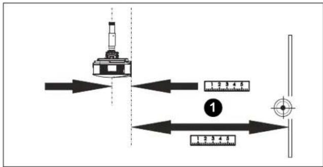
Figure 2
-
Remove adjacent ceiling tiles for access. Do NOT remove tile affected by installation of extension column.
-
Lay assembly (A) on top of ceiling tile so that extension column support is aligned with location noted in Step 1.
-
Mark locations for hanger brackets (D) on tray (A) with pencil (See Figure 3). Each hanger bracket (D) may be installed in one of 3 locations in each corner of tray (A), dependent upon specific installation requirements. Ensure brackets (D) are located as follows:
-
On sides of tray (A) adjacent to primary (1-1/2" (38mm) high) rails of ceiling framework.
- As close to corner of tray (A) as installation allows.
NOTE: Proceed to the appropriate installation situation.
- Installation on Top of Existing Tile only: Mark the following locations on ceiling tile with pencil (See Figure 3):
A. Extension column hole
B. OPTIONAL: Electrical cutout
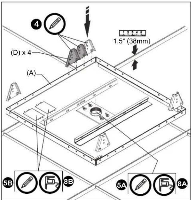
Figure 3
-
Examine ceiling structure (concrete, steel truss, or wood) above tray (A) to identify the following (See Figure 4):
-
Four support wire anchor locations, each approximately 15^ outboard of corresponding hanger bracket (D). Mark locations with pencil.
• One safety cable anchor location directly above center of tray (A). Mark location with pencil.
NOTE: Hanger brackets (D) and turnbuckles (F) are installed later; they are shown for reference only. (See Figure 4)
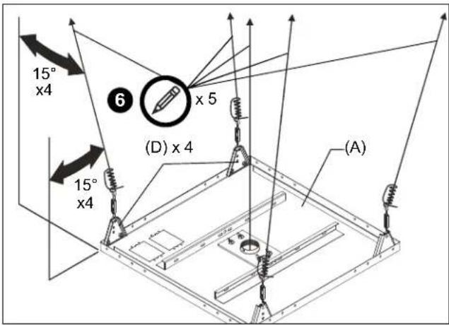
Figure 4
- Remove tray (A) and affected ceiling tile.
- Installation on Top of Existing Tile only: Cut the following holes in ceiling tile (See Figure 3):
A. Cut extension column hole in tile at marked location, 2" (51mm) minimum diameter.
B. OPTIONAL: Cut electrical box opening in tile at marked location. Install UL Listed electrical box (not included) to tray (A) following instructions included with electrical box.
- Install four hanger brackets (D) to tray (A) with eight 1/4-20 x 3/8" Phillips head screws (K) at marked locations (See Figure 5). Ensure brackets (D) are installed against inside flanges of tray (A).
NOTE: Some installations may require that one or more brackets (D) be installed after tray (A) is positioned in suspended ceiling framework.
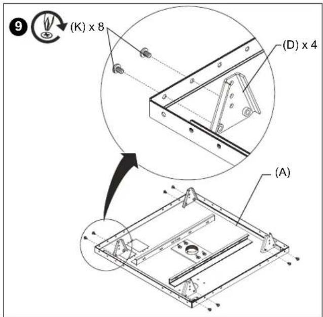
Figure 5
- Loosely install ceiling framework clamps (E) to hanger brackets (D) using 1/4-20 x 1" Phillips head screws (L). (See Figure 6)
• FOR INSTALLATION ON TOP OF EXISTING TILE: Use lower hole on bracket (D).
• FOR REPLACEMENT OF EXISTING TILE: Use middle hole on bracket (D).
NOTE: Top hole reserved for installation of turnbuckle (F).

Figure 6
- Cut support wire (B) into 4 pieces of equal length.
NOTE: Ceiling structure more than 3ft (0.91m) above tray (A) will require additional #12 annealed steel wire.
SUPPORT WIRE INSTALLATION

WARNING: Failure to provide adequate structural strength for this component can result in serious personal injury or damage to equipment! It is the installer's responsibility to make sure the structure to which this component is attached can support five times the combined weight of all equipment. Reinforce the structure as required before installing the component.
Solid Concrete Ceiling Structure

WARNING: Anchors must be installed into structurally sound solid concrete with a minimum thickness of 1.75" (44.5mm) or greater. Installation into concrete that exhibits cracking, spalling, or other defects may result in failure of anchor and serious personal injury or damage to equipment!
- Drill 1/4" (6.4mm) diameter x 1-3/8" (35mm) deep hole at each marked wire anchor support location. (See Figure 7) Ensure hole is at least 2-1/2" (64mm) from nearest concrete edge. Remove debris from hole.
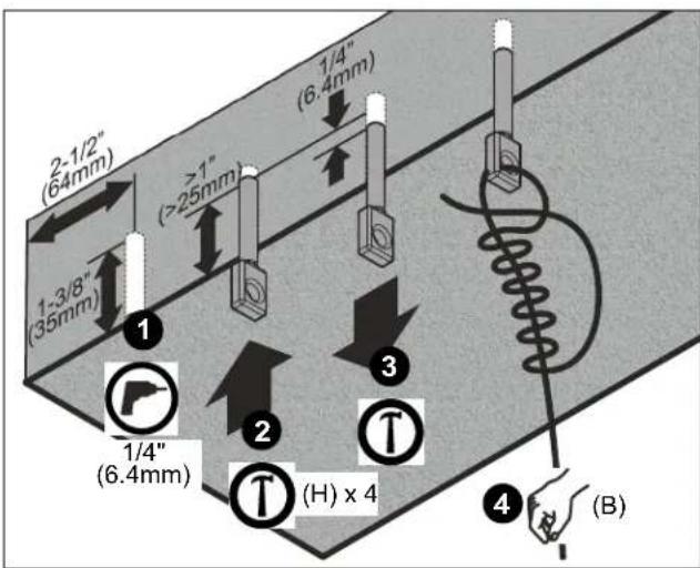
Figure 7
- Tap anchor (H) into each hole to a depth of at least 1" (25mm). (See Figure 7)

WARNING: Failure to properly set anchor may result in failure of anchor and serious personal injury or damage to equipment!
- Using claw portion of hammer, set each anchor (H) by pulling it out of hole approximately 1/4" (6.4mm). (See Figure 7)
- Insert support wire (B) through hole in anchor. Twist wire tightly around itself at least four complete turns, and then thread loose end between anchor and first turn. (See Figure 7) Repeat for three remaining support locations.
Steel Truss Ceiling Structure
- Route end of support wire (B) over truss at marked wire anchor support location. Twist wire tightly around itself at least four complete turns, and then thread loose end between truss and first turn. (See Figure 8) Repeat for three remaining support locations.
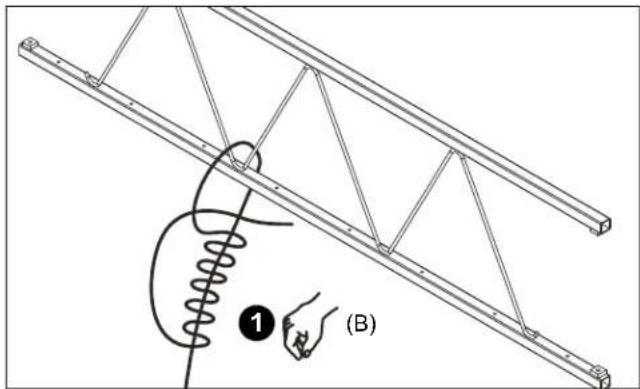
Figure 8
Wood Ceiling Structure

WARNING: Anchors must be installed into wood with a minimum thickness of 1-1/2" (3.81 cm) and a minimum depth of 3-1/2" (8.89 cm) or greater.
- Drill 5/32" (4.0mm) diameter x 2" (51mm) deep hole at each marked wire anchor support location. (See Figure 9) Remove debris from hole.

Figure 9
- Fully thread eye lag (J) into each hole. (See Figure 9)
- Insert support wire (B) through eye lag (J). Twist wire tightly around itself at least four complete turns, and then thread loose end between eye and first turn. (See Figure 9) Repeat for three remaining support locations.
TRAY INSTALLATION
- Reinstall ceiling tile (if applicable) and assembly (A). Ensure proper orientation for location of hole.
- Slip ceiling framework clamps (E) over primary (1-1/2" (38mm) high) rails of ceiling framework. (See Figure 10) Tighten 1/4-20 x 1" Phillips head screws (L) previously installed.

Figure 10
- Adjust hooks and eyes on turnbuckles (F) so that approximately 1/4-1/2" (6.4-12.7mm) of threads show on inside of turnbuckles (See Figure 11).
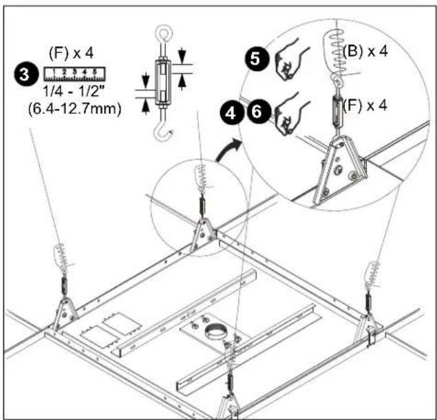
Figure 11
-
Attach the hook end of each turnbuckle (F) to the corresponding hanger bracket (D) upper hole. (See Figure 11)
-
Insert corresponding hanging wire (B) through eye in turnbuckle (F). Pull wire tight and twist back around itself at least 4 complete turns, then thread loose end between eye and first turn. (See Figure 11) Repeat for 3 remaining turnbuckles (F).

CAUTION: Failure to properly tension cables (B) may result in damage to ceiling tile framework!
- Adjust turnbuckles (F) until tray (A) is supported entirely and evenly by all four support wires (B), but not so tight as to distort suspended ceiling framework. (See Figure 11)
SAFETY CABLE INSTALLATION
- Attach safety cable (C) to steel truss ceiling structure at marked location.
NOTE: If no suitable steel truss structure exists, install concrete anchor (Simpson Tie-Wire concrete anchor #TWD25112, not included) or wood eye lag screw (ASTM F541-12 .262x1 5/16 x 1.00 zinc plated steel eye-bolt, not included) per manufacturer's installation instructions.
A. For ceiling structure less than 4ft (1.2m) from ceiling tray (A) (See Figure):
- Attach one end of cable (C) to channel in tray (A). Secure with wire clamp (G).
- Route opposite end of cable (C) over truss, and attach to opposite channel in tray (A). Remove cable slack and secure with wire clamp (G).
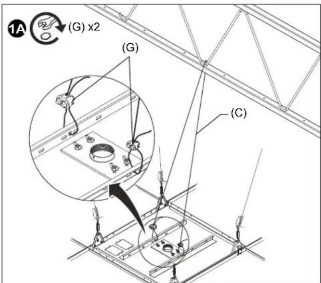
Figure 12
B. For ceiling structure from 4 - 7ft (1.2 - 2.1m) from ceiling tray (A) (See Figure 13):
- Route one end of cable (C) over truss and secure to itself with wire clamp (G).
- Route opposite end of cable (C) through both channels in tray (A). Remove cable slack and secure to itself with wire clamp (G).
C. For ceiling structure more than 7ft above tray (A):
• Additional 1/8" diameter steel safety cable will be required.
- Attach cable to tray (A) per step 1.A or 1.B
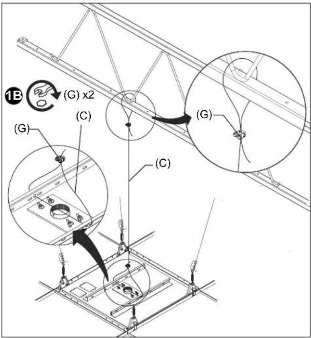
Figure 13
EXTENSION COLUMN INSTALLATION

WARNING: Exceeding the weight capacity can result in serious personal injury or damage to equipment! It is the installer's responsibility to make sure the combined weight of all components attached to the ELPMBP05 does not exceed 250 lbs (113 kg).
- Install 1-1/2" NPT or NPSM following ANSI/ASME B1.20.1 (Schedule 40, 0.154" minimum thickness steel or aluminum - ASTM B221) threaded extension column (not included) into extension column support until tight, with a minimum of four threads engaged.
NOTE: If installation instructions are not available, contact Chief for assistance.
- Install one 10-24 x 1/4" button head screw (M) into extension column support, tightening firmly against column. (See Figure 14)
- OPTIONAL: Install one 10-24 x 1/4" button head security screw (N) through locking collar (P) into extension column support, tightening firmly against column.
NOTE: Locking collar (P) is designed to spin, even when screw (N) is tight.
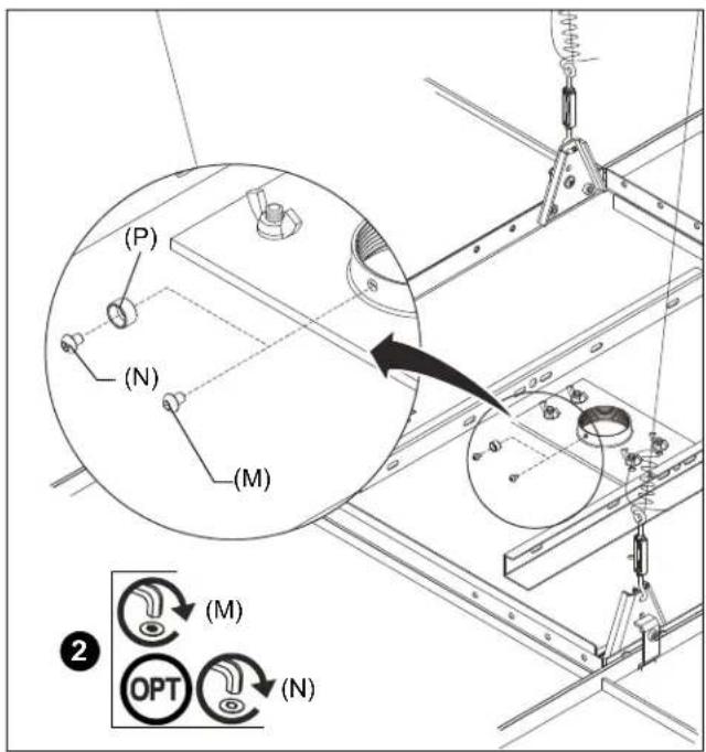
Figure 14
- Reinstall remaining ceiling tiles as required.
LIMITED WARRANTY
With the exception of electrical products, Milestone warrants its products to be free of defects in material and workmanship for 10 years. All warranties are in effect beginning the date the product was invoiced by Milestone. Electrical mechanisms (such as lift products) have a 1-year limited warranty. All warranties are in effect for the original purchaser only. Milestone disclaims liability for any modifications, improper installation and/or installations over the specified weight capacity. Milestone also disclaims liability for any modifications made to electrical mechanisms, improper installation, incorrect voltage connection and/or installations over the stated weight capacity. All Electrical Mechanisms are intended for indoor use only and failure to comply will void warranty. Milestone's sole warranty obligation to the owner of its products is to repair or replace (at Milestone's discretion) defective products at no charge to the original purchaser within the warranty period. The purchaser is responsible for returning the product to Milestone via prepaid shipping. To the maximum extent permitted by applicable law, Milestone disclaims any other warranties, express or implied, including warranties of fitness for a particular purpose and warranties of merchantability. Milestone will not be liable for any damages whatsoever arising out of the use or inability to use Milestone products, even if Milestone has been advised of the possibility of such damages. Milestone bears no responsibility for incidental or consequential damages. This includes, but is not limited to, any labor charges for the repair of Milestone products performed by someone other than a Milestone employee. Because some states and jurisdictions do not allow the exclusion or limitation of liability for consequential or incidental damages, the above limitation may not apply. Milestone will not be responsible for damage to Milestone products caused by misuse, abuse, failure to properly package the product for return to Milestone or for damage caused by carriers during shipment to or from Milestone. Any repairs to Milestone products required due to misuse, abuse or shipping damage or repairs of defective Milestone product outside the warranty period will be performed at the current rates established by Milestone for factory service.
Distributed by:
Epson America, Inc.
3840 Kilroy Airport Way
Long Beach, CA 90806
Manufactured by:
Milestone AV Technologies
A 6436 City West Parkway, Eden Prairie, MN 55344
P 800.582.6480
F 877.894.6918
E info@milestone.com (Tech Support 7:00am - 7:00pm CST)
www.milestone.com
8800-002776 Rev01
09/15

CLAUSE DE NON-RESPONSABILITÉ
natural_image
Technical diagram of a ceiling-mounted projector mounted on a grid-patterned floor, with no visible text or symbols.Figure 1
Figure 5
Figure 6
Figure 8
Figure 14
natural_image
Diagram of ceiling-mounted air duct system with directional arrows indicating airflow or movement (no text or symbols)Figura 1
Figura 5
Figura 6
Figura 8
Figura 14
D 6436 City West Parkway, Eden Prairie, MN 55344
T 800.582.6480
F 877.894.6918
natural_image
Technical diagram of a ceiling-mounted air duct system with directional arrows indicating airflow or movement (no text or symbols present)Figura 1
Figura 4
Figura 5
Figura 6
Figura 8
Figura 9
Figura 10
Figura 14
A 6436 City West Parkway, Eden Prairie, MN 55344
T 800.582.6480
F 877.894.6918
With the exception of electrical products, Milestone warrants its products to be free of defects in material and workmanship for 10 years. All warranties are in effect beginning the date the product was invoiced by Milestone. Electrical mechanisms (such as lift products) have a 1-year limited warranty. All warranties are in effect for the original purchaser only. Milestone disclaims liability for any modifications, improper installation and/or installations over the specified weight capacity. Milestone also disclaims liability for any modifications made to electrical mechanisms, improper installation, incorrect voltage connection and/or installations over the stated weight capacity. All Electrical Mechanisms are intended for indoor use only and failure to comply will void warranty. Milestone's sole warranty obligation to the owner of its products is to repair or replace (at Milestone's discretion) defective products at no charge to the original purchaser within the warranty period. The purchaser is responsible for returning the product to Milestone via prepaid shipping. To the maximum extent permitted by applicable law, Milestone disclaims any other warranties, express or implied, including warranties of fitness for a particular purpose and warranties of merchantability. Milestone will not be liable for any damages whatsoever arising out of the use or inability to use Milestone products, even if Milestone has been advised of the possibility of such damages. Milestone bears no responsibility for incidental or consequential damages. This includes, but is not limited to, any labor charges for the repair of Milestone products performed by someone other than a Milestone employee. Because some states and jurisdictions do not allow the exclusion or limitation of liability for consequential or incidental damages, the above limitation may not apply. Milestone will not be responsible for damage to Milestone products caused by misuse, abuse, failure to properly package the product for return to Milestone or for damage caused by carriers during shipment to or from Milestone. Any repairs to Milestone products required due to misuse, abuse or shipping damage or repairs of defective Milestone product outside the warranty period will be performed at the current rates established by Milestone for factory service.
Distributed by:
Epson America, Inc.
3840 Kilroy Airport Way
Long Beach, CA 90806
Manufactured by:
Milestone AV Technologies
A 6436 City West Parkway, Eden Prairie, MN 55344
P 800.582.6480
F 877.894.6918
E info@milestone.com (Tech Support 7:00am - 7:00pm CST)
www.milestone.com
8800-002776 Rev01
09/15


- INSTALLATION INSTRUCTIONS
- LEGEND / LÉGENDE / REFERENCIAS / LEGENDA
- Tighten Fastener
- Phillips Screwdriver
- IMPORTANT SAFETY INSTRUCTIONS!
- SITE PREPARATION / ASSEMBLY
- SUPPORT WIRE INSTALLATION
- Solid Concrete Ceiling Structure
- Steel Truss Ceiling Structure
- Wood Ceiling Structure
- TRAY INSTALLATION
- SAFETY CABLE INSTALLATION
- EXTENSION COLUMN INSTALLATION
- LIMITED WARRANTY
- CLAUSE DE NON-RESPONSABILITÉ
Brand : EPSON
Model : ELPMBP05
Category : Projector