
WALL05DTMWS - Speaker Monacor - Free user manual and instructions
Find the device manual for free WALL05DTMWS Monacor in PDF.
User questions about WALL05DTMWS Monacor
0 question about this device. Answer the ones you know or ask your own.
Ask a new question about this device
Download the instructions for your Speaker in PDF format for free! Find your manual WALL05DTMWS - Monacor and take your electronic device back in hand. On this page are published all the documents necessary for the use of your device. WALL05DTMWS by Monacor.
USER MANUAL WALL05DTMWS Monacor
natural_image
White outdoor speaker with mesh grille and front panel (no visible text or symbols)WALL-05DTM/WS
Bestellnummer • Order Number • Référence num. 1000788
BEDIENUNGSANLEITUNG
INSTRUCTION MANUAL
MODE D'EMPLOI
text_image
1 2 3 4 2 ①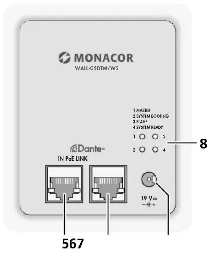
text_image
MONACOR WALL-05DTM/WS 1 MASTER 2 SYSTEM BOOTING 3 SLAVE 4 SYSTEM READY 1 ○ ○ 2 3 ○ ○ 4 Dante® IN PoE LINK 19 V= - + + 567 8English ..... Page 10
Français ..... Page 16
https://www.audinate.com/products/software/dante-controller
https://www.audinate.com/resources/technical-documentation

text_image
Dante Controller - Device View (WALL-05DTM-83ec27) File Device View Help Receive Status Latency Device Config Network Config AES67 Config WALL-05DTM-83ec27 Rename Device WALL-05DTM-83ec27 Apply Sample Rate Sample Rate: 48k Pull-up/down: This device does not support Pull-up/down configuration. Encoding Preferred Encoding: PCM 32 Clocking Unicast Delay Requests: Disabled Device Latency Latency: 1,0 msec Reset Device Reboot Clear Config③ Device-View vom WALL-05DTM
text_image
Dante Controller - Network View File Device View Help Primary Leader Clock: AKBWALL-837ec8 Routing Device Info Clock Status Network Status Events Dante® Filter Transmitters Filter Receivers Transmitters (2) DADC-144DT OUT 01 OUT 02 OUT 03 OUT 04 Messe2-PC 01 02 03 04 05 06 07 08 09 10 11 12 13 14 15 + Receivers (4) + AKBWALL-837ec8 + DADC-144DT + Messe2-PC + WALL-05DTM-83ec27 [Q-10.1] 30W Output P: Unmanaged Multicast Bandwidth: 0 bps Event Log: Clock Status Monitor:Abtastrate: 44,1–96 kHz
Datenschnittstelle
Active Speaker for Dante Networks
These instructions are intended for audio system installers with knowledge of network technology. Please read the instructions carefully prior to operation and keep them for later reference.
The figures relating to the text below can be found on page 2.
1 Overview
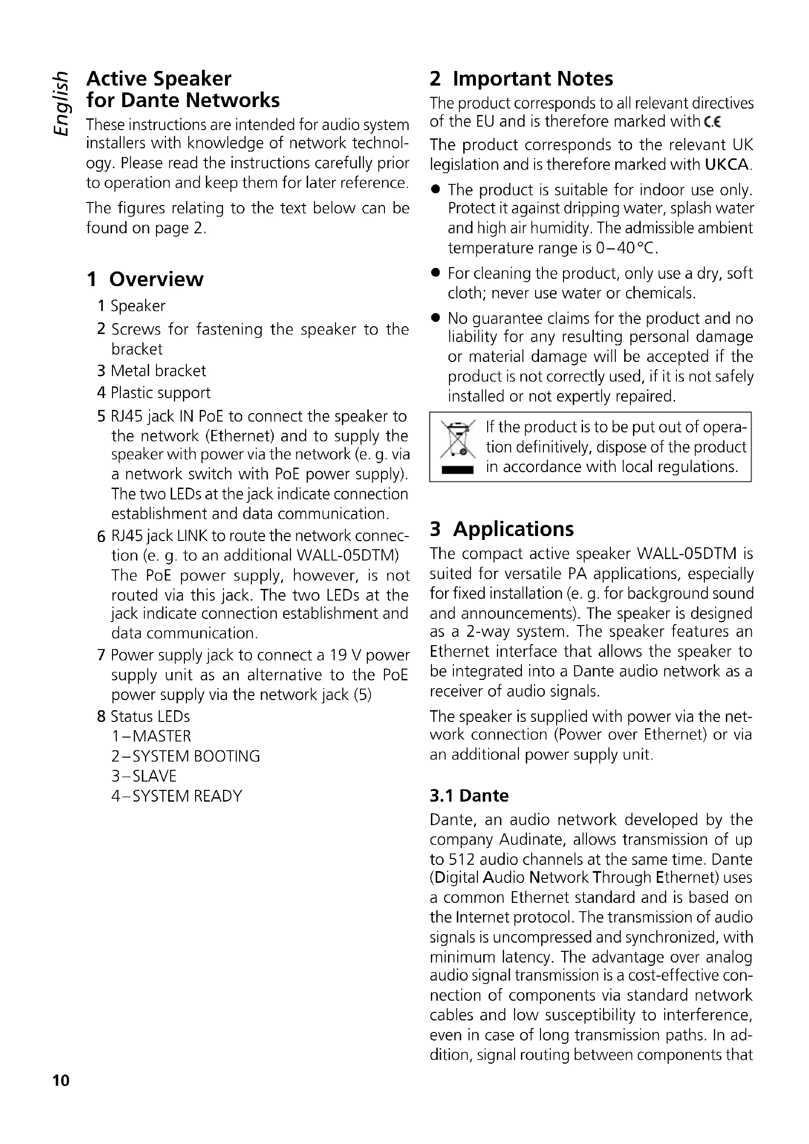
1 Speaker
2 Screws for fastening the speaker to the bracket
3 Metal bracket
4 Plastic support
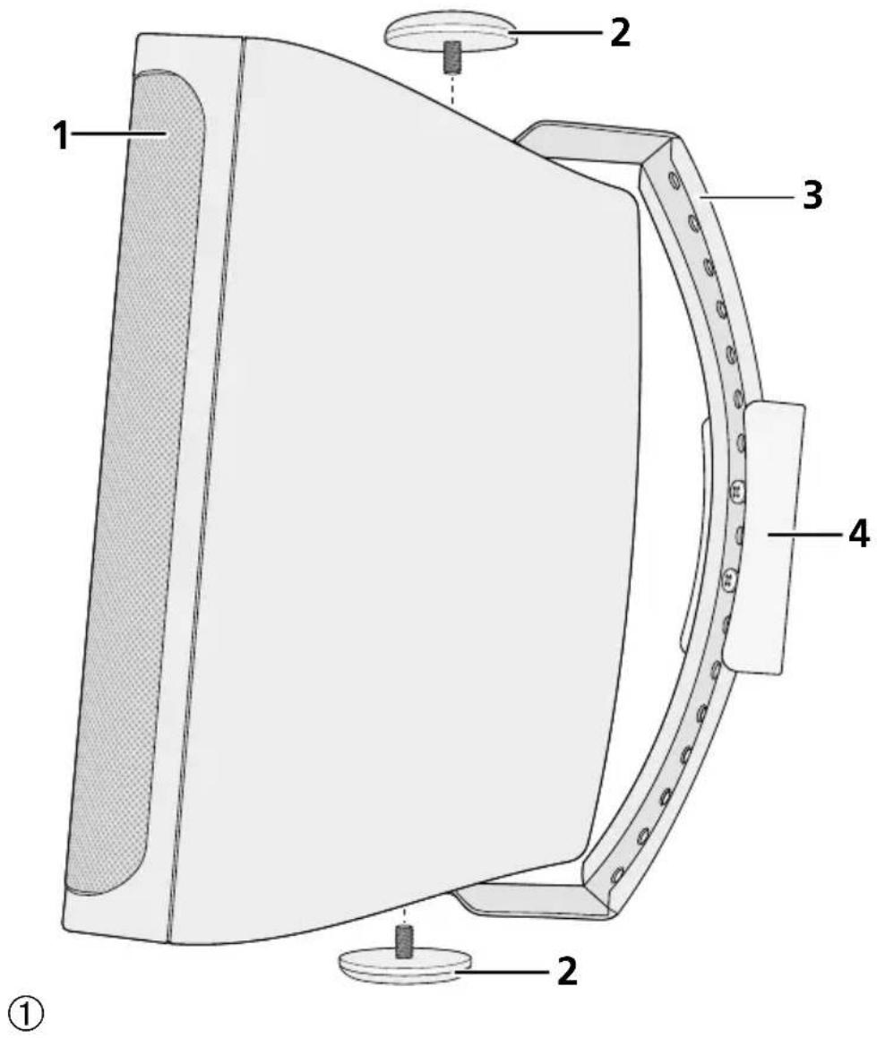
5 RJ45 jack IN PoE to connect the speaker to the network (Ethernet) and to supply the speaker with power via the network (e.g. via a network switch with PoE power supply). The two LEDs at the jack indicate connection establishment and data communication.
6 RJ45 jack LINK to route the network connection (e. g. to an additional WALL-05DTM) The PoE power supply, however, is not routed via this jack. The two LEDs at the jack indicate connection establishment and data communication.
7 Power supply jack to connect a 19 V power supply unit as an alternative to the PoE power supply via the network jack (5)
8 Status LEDs
1-MASTER
2-SYSTEM BOOTING
3-SLAVE
4-SYSTEM READY
2 Important Notes
The product corresponds to all relevant directives of the EU and is therefore marked with C.€
The product corresponds to the relevant UK legislation and is therefore marked with UKCA.
- The product is suitable for indoor use only. Protect it against dripping water, splash water and high air humidity. The admissible ambient temperature range is 0–40°C.
- For cleaning the product, only use a dry, soft cloth; never use water or chemicals.
- No guarantee claims for the product and no liability for any resulting personal damage or material damage will be accepted if the product is not correctly used, if it is not safely installed or not expertly repaired.

If the product is to be put out of operation definitively, dispose of the product in accordance with local regulations.
3 Applications
The compact active speaker WALL-05DTM is suited for versatile PA applications, especially for fixed installation (e.g. for background sound and announcements). The speaker is designed as a 2-way system. The speaker features an Ethernet interface that allows the speaker to be integrated into a Dante audio network as a receiver of audio signals.
The speaker is supplied with power via the network connection (Power over Ethernet) or via an additional power supply unit.
3.1 Dante
Dante, an audio network developed by the company Audinate, allows transmission of up to 512 audio channels at the same time. Dante (Digital Audio Network Through Ethernet) uses a common Ethernet standard and is based on the Internet protocol. The transmission of audio signals is uncompressed and synchronized, with minimum latency. The advantage over analog audio signal transmission is a cost-effective connection of components via standard network cables and low susceptibility to interference, even in case of long transmission paths. In addition, signal routing between components that
have once been connected can be changed by software at any time. In the Dante network, devices configured as transmitters are used as signal sources. By means of the program "Dante Virtual Soundcard" from the company Audinate, computers can also be used as signal sources, e.g. to feed audio files replayed on the computer to the Dante network.
The speaker WALL-05DTM is equipped with one Dante receiving channel. The receiving channel is assigned to any transmitting channel in the Dante network via the Dante configuration program "Dante Controller" (chapter 5).
Dante ^® is a trademark of Audinate Pty Ltd.
4 Installation
The speaker is designed for being installed on a wall, but it can also be set up on its own.
To install the speaker:
1) Remove the plastic support (4) from the metal bracket (3). Then use two screws to fasten the support at the desired location (e.g. wall or ceiling).
2) Fasten the metal bracket (3) to the plastic support, using the two recessed head screws of the bracket. Use the holes in the metal bracket which are most suitable for the desired speaker alignment.
3) Use the screws (2) to fasten the speaker (1) to the metal bracket. Align the speaker to the desired sound zone before fastening the screws.
4.1 Network
To feed in audio signals via a Dante network, connect the jack IN PoE (5) to an individual computer, a local computer network or (via a router, for example) to a large computer network. For correct configuration, knowledge of network technology is indispensable. The speaker can be supplied with power via the same connection jack (Chapter 4.2).
For integration into a Dante network, the speaker must be connected to an Ethernet switch that supports at least Fast Ethernet (transmission rate 100 Mbit /s).
The interface of the speaker is preset to automatic address assignment; configuration via the program "Dante Controller" is possible (chapter 5.1).
The jack LINK (6) can be used for routing the network connection, e. g. directly to an additional WALL-05DTM. The PoE power supply, however, is not routed via this jack.
4.2 Power supply
Power supply can be made via the network connection (Power over Ethernet): Connect the jack IN PoE (5) to a network connection providing PoE (e. g. PoE switch). If power supply via PoE is not possible or if a higher output power is required, use a DC power connector with the dimensions 5.5/2.5 mm(outside/insidediameter) to connect a regulated 19 V DC power supply unit with a permanent rating of 2.5 A to the jack 19 V = (7). Observe the correct polarity: inside contact = +.
Lower supply voltages are also possible, resulting in a corresponding reduction of the amplifier power that can be achieved.
| supply voltage nominal power | |
| 19V30W | |
| 15V21W | |
| 12V15W | |
| 9V8W | |
| PoE 20W | |
5 Configuration of the Dante Network
WALL-05DTM is configured as a receiver in the Dante network by means of the program “Dante Controller”, available as a free download on the website of the company Audinate. The settings made via the program will be saved in the corresponding transmitters and receivers of the Dante network so that the program is only required for network configuration but not for normal operation.
Download and install the program "Dante Controller" from the Audinate website via the following Internet address:
https://www.audinate.com/products/software/dante-controller
5.1 Configuration of the device with the Dante Controller
1) Start the Dante Controller.
2) Wait for the desired Dante transmitter and WALL-05DTM to appear in the matrix (under "Receivers").
Note: If WALL-05DTM or one of the devices fails to appear, the reason may be that
– the corresponding device has not been switched on
– the device is in a different subnet
– the device is not able to synchronize with the other Dante devices.
However, if one of the two last-mentioned reasons applies, the Dante device should at least appear under the tab "Device Info" or "Clock Status" in the network view. It may solve the problem to switch the device off and on again or to disconnect and reconnect the LAN connection. For further information please refer to the user manual of the Dante Controller from Audinate.
3) In the menu bar of the Dante Controller, select "Device/Device View" or use the shortcut Ctrl+D. The Device View window will open.
4) Select "WALL-05DTM" in the bar of the dropdown menu appearing beneath the menu bar.
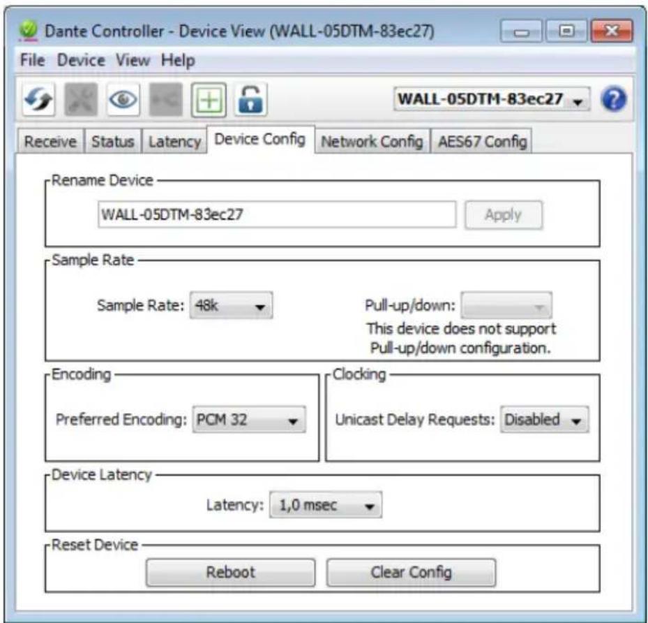
5) The third bar can be used to indicate information on the device and to make settings. Select the tab "Device Config" (fig. 3).
6) In the field "Rename Device", the name used for the device in the Dante network can be changed (e.g. to a specific name referring to the place of installation). Click "Apply" to confirm the change.
7) Adjust the "Sample Rate" to the desired Dante transmitter or set a different common sample rate for both devices, if required.
8) Use the tab "Network Config" to change the network settings for the Dante interface of WALL-05DTM, if required.
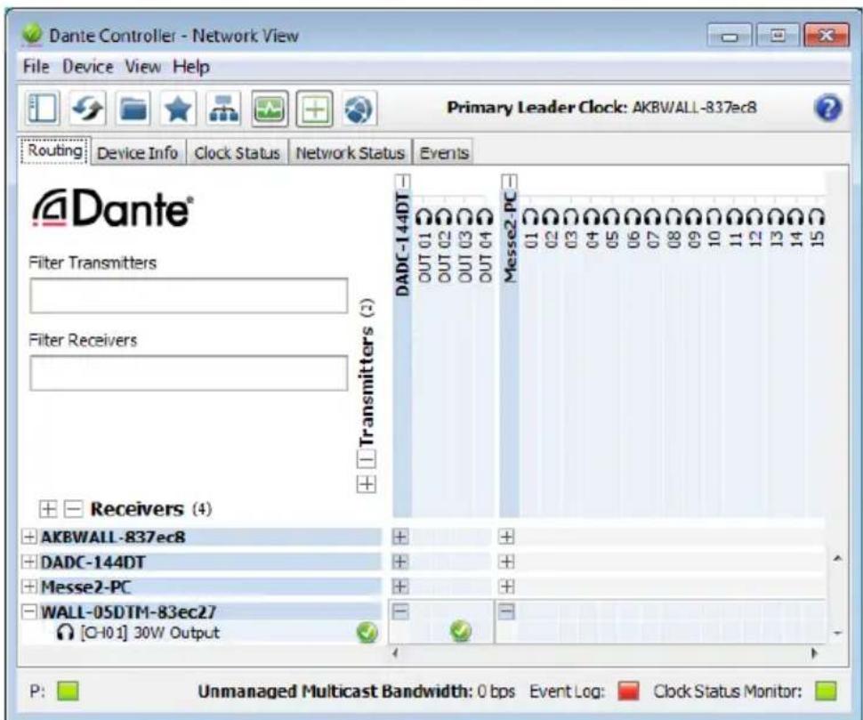
5.2 Routing with the Dante Controller
In the "Network View" window under the "Routing" tab, the transmitters of the Dante network are arranged in columns ("Transmitters") and the receivers in rows ("Receivers"). The transmitting and receiving channels of the devices can be assigned to each other via this matrix.
1) Click on the ⊕ in the column of the desired Dante transmitter to display its transmitting channels and click on the ⊕ in the row of WALL-05DTM to display its receiving channel (Fig. 4).
2) Navigate from the column of the desired transmitting channel to the row of the receiving channel of WALL-05DTM and click the field at the intersection point.
3) Wait for the field to show a green circle with a white check mark √.
An English user guide for the Dante Controller is available for download on the Audinate website:
https://www.audinate.com/resources/technical-documentation
text_image
Dante Controller - Device View (WALL-05DTM-83ec27) File Device View Help Receive Status Latency Device Config Network Config AES67 Config WALL-05DTM-83ec27 Rename Device WALL-05DTM-83ec27 Apply Sample Rate Sample Rate: 48k Pull-up/down: This device does not support Pull-up/down configuration. Encoding Preferred Encoding: PCM 32 Clocking Unicast Delay Requests: Disabled Device Latency Latency: 1,0 msec Reset Device Reboot Clear Config③ Device View of WALL-05DTM

text_image
Dante Controller - Network View File Device View Help Primary Leader Clock: AKBWALL-837ec8 Routing Device Info Clock Status Network Status Events Dante® Filter Transmitters Filter Receivers Transmitters (2) DADC-144DT OUT 01 OUT 02 OUT 03 OUT 04 Messe2-PC 01 02 03 04 05 06 07 08 09 10 11 12 13 14 15 + Receivers (4) + AKBWALL-837ec8 + DADC-144DT + Messe2-PC + WALL-05DTM-83ec27 [Q-10.1] 30W Output P: Unmanaged Multicast Bandwidth: 0 bps Event Log: Clock Status Monitor:④ Audio routing from the audio source DADC-144DT to the receiver WALL-05DTM
6 Before Operation
When connecting the device to the power supply (via external power supply unit or PoE), the status LEDs (8) light up briefly in the following order:
1) 2-SYSTEM BOOTING
2) 1-MASTER and 2-SYSTEM BOOTING
3) 1-MASTER and 4-SYSTEM READY
When the speaker is set up in the Dante network as a clock slave, the following LEDs are permanently on:
3-SLAVE and 4-SYSTEM READY
If both LEDs 1 and 2 flash, a connection error has occurred. In this case, disconnect WALL-05DTM from the power supply (or PoE connection) and reconnect after a minimum of 30 seconds.
6.1 Level adjustment
The speaker itself has no control elements. The volume is adjusted via an audio signal from a Dante signal source (transmitter) with a corresponding digital level value.
Only set the signal level at the audio source to such a value that the signal from the speaker is not distorted.
Note: The maximum possible signal level depends on the level of the supply voltage used. The higher the supply voltage, the higher the level values that can be reproduced without distortion.
CAUTION

Never adjust the audio system to a very high volume. Permanent high volumes may damage your hearing!
7 Specifications
System: 2-way system
Frequency range: 62–20 000 Hz
Speaker configuration
Bass speaker: 13 cm (5")
Tweeter: 13 mm ( 12 )
Sensitivity: 89dB/W/m
max. SPL: 105 dB
Amplifier power (nominal power)
with PoE power supply: ..... 20W
with 19 V power supply: ..... 30W
with 15 V power supply: ..... 21 W
with 12 V power supply: ..... 15W
with 9 V power supply: ..... 8 W
Dante input signal
Number of channels: ..... 1
Resolution: 16–32 bits
Sampling rate: 44.1–96 kHz
Data interface
Ethernet:.... RJ45 jack
Admissible ambient temperature: .. 0–40°C
Power supply
Power over Ethernet: ..... PoE+ in accordance with IEEE 802.3at-2009
or via power supply jack: ..... == 9 - 19V/2.5A
Dimensions
Width: 163 mm
Height: 252 mm
Depth: 165mm
Weight: 2.12 kg
Subject to technical modification.
https://www.audinate.com/products/software/dante-controller
https://www.audinate.com/resources/technical-documentation

text_image
Dante Controller - Device View (WALL-05DTM-83ec27) File Device View Help Receive Status Latency Device Config Network Config AES67 Config WALL-05DTM-83ec27 Rename Device WALL-05DTM-83ec27 Apply Sample Rate Sample Rate: 48k Pull-up/down: This device does not support Pull-up/down configuration. Encoding Preferred Encoding: PCM 32 Clocking Unicast Delay Requests: Disabled Device Latency Latency: 1,0 msec Reset Device Reboot Clear Config③ Device View de la WALL-05DTM
