
SDABS900 - Dashcam PIONEER - Free user manual and instructions
Find the device manual for free SDABS900 PIONEER in PDF.
| Product type | Blind spot detection and lane change assist system |
| Brand | Pioneer |
| Model | SDA-BS900 |
| Detection angle | 70° (horizontal) |
| Detection range | Up to 25 m (82 ft) rearward |
| Activation speed range | Above 29 km/h (18 mph) |
| Supply voltage | 9 VDC – 18 VDC |
| Power consumption | 400 mA |
| Protection rating (radar sensors) | IPX6/IPX7 |
| Operating temperature | -40 °C to 85 °C (-40 °F to 185 °F) |
| Fuse rating | 2 A |
| Box contents | 2 radar sensors, 2 LED indicators, 1 GPS antenna, 1 speaker, wiring harness, angle tool, brackets, rivets |
| Installation | Professional installation recommended (do not install yourself) |
| Warranty | 3-year limited warranty |
| Maintenance | Clean sensors with a soft cloth; avoid harsh chemicals |
| Safety | Do not obstruct sensors; do not mount indicators near airbags |
Frequently Asked Questions - SDABS900 PIONEER
User questions about SDABS900 PIONEER
0 question about this device. Answer the ones you know or ask your own.
Ask a new question about this device
Download the instructions for your Dashcam in PDF format for free! Find your manual SDABS900 - PIONEER and take your electronic device back in hand. On this page are published all the documents necessary for the use of your device. SDABS900 by PIONEER.
USER MANUAL SDABS900 PIONEER
Instruction Manual and Installation Guide
Important (Serial number)
The serial number is located on the bottom of the main unit. For your own security and convenience, be sure to record the number.
Contents
Thank you for buying this Pioneer product.
Please read through these instructions so you will know how to operate this product properly. After you have finished reading the instructions, keep this document in a safe place for future reference.
■ Precaution....3
Information to Customer....3
Important Safety Information....4
After-Sales Service ....5
Three Year Limited Warranty....5
Visit our Website ....5
■ Alert Conditions......6
System Indicators......6
Item List 7
■ Installation Diagram ....8
■ Wire Connection Diagram ......9
■ Installation Guide ....10
Step 1: Sensor heads Installation ....11
Step 2: Left/Right Turn Signal Installation....12
Step 3: LED Indicator Installation ....13
Step 4: Speaker Installation....13
Step 5: GPS Antenna Installation ....14
Step 6: Wires Installation ....14
■ Technical Specifications ....15
Troubleshooting......16
Precaution
Information to Customer
FCC ID: IYASDA-BS900
IC: 25782-SDABS900
- This device contains license-exempt transmitter(s)/receiver(s) that complies with Part 15 of FCC Rules and Innovation, Science, and Economic Development Canada license-exempt RSS(s). Operation is subject to the following two conditions: (1) this device may not cause interference, and (2) this device must accept any interference, including interference that may cause undesired operation of this device.
- The antenna cannot be removed (or replaced) by user.
- This equipment complies with FCC/ISED radiation exposure limits set forth for an uncontrolled environment and meets the FCC radio frequency (RF) Exposure Guidelines and RSS-102 of the ISED radio frequency (RF) Exposure rules. This equipment has very low levels of RF energy that are deemed to comply without Maximum Permissible Exposure evaluation (MPE), but the equipment should be installed and operated at least 20cm from a person's body.
Information to User
- Alteration or modifications carried out without appropriate authorization may invalidate the user's right to operate the equipment.
NOTE: This equipment has been tested and found to comply with the limits for a Class B digital device, pursuant to Part 15 of the FCC Rules. These limits are designed to provide reasonable protection against harmful interference in a residential installation. This equipment generates, uses and can radiate radio frequency energy and, if not installed and used in accordance with the instructions, may cause harmful interference to radio communications. However, there is no guarantee that interference will not occur in a particular installation. If this equipment does cause harmful interference to radio or television reception, which can be determined by turning the equipment off and on, the user is encouraged to try to correct the interference by one or more of the following measures:
- Reorient or relocate the receiving antenna.
- Increase the separation between the equipment and receiver.
- Connect the equipment into an outlet on a circuit different from that to which the receiver is connected.
- Consult the dealer or an experienced radio/TV technician for help.
FEDERAL COMMUNICATIONS COMMISSION SUPPLIER'S DECLARATION OF CONFORMITY
Product Name: BLIND SPOT DETECTION / LANE CHANGE ASSIST SYSTEM
Model Number: SDA-BS900
Responsible Party Name: PIONEER ELECTRONICS (USA) INC.
SERVICE SUPPORT DIVISION
Address: 2050 W. 190TH STREET, SUITE 100, TORRANCE, CA 90504, U.S.A.
Phone: 1-800-421-1404
URL: http://www.pioneerelectronics.com
- Special vehicle conditions that should be considered
During system startup and initialization, it may take up to 2 minutes for the system to establish a GPS connection. If the vehicle is driven before a GPS connection is established or if the GPS connection is interrupted (inside a tunnel, parking structure, etc.), the system may not function properly, producing incorrect or false warnings or failing to produce a warning. Once the GPS connection is established or re-established, both LED indicators will flash twice to indicate the system is ready for use.
This system can be used on any vehicle except vehicles with metal bumpers, i.e. Trucks. When mounting the sensors, assure that the sensors are not obstructed by any metal object as the operation of the product can be affected by the metal object interfering with the system.
The following may compromise the effectiveness of the system:
- Incorrect installation angle.
• Vehicles with metal obstructions in front of the sensor head.
Improperly mounted sensor location on vehicle, i.e. center of vehicles bumper location.
- Situations that cannot be detected
- Your vehicle is moving slower than the sensing speed setting, such as in slow moving traffic.
- When your vehicle is reversing, the relative speed between your vehicle and objects is less than 5 mph (8 km/h).
If a vehicle is approaching / overtaking your vehicle and the relative speed between your vehicle and the overtaking vehicle is greater than 37 mph (60 km/h). For example, if you are traveling at 41 mph (66 km/h), the system cannot detect vehicles approaching from behind if their speed exceeds 78 mph (126 km/h).
Situations that may affect system detection accuracy
- Metal objects are in the direct path of the sensing signal.
- Weather such as heavy rain and snow, and icy road conditions, which can cause changes in sensitivity.
Gravel roads, which may cause interference due to dust and flying stones.
Important Safety Information
WARNING
THIS PRODUCT FUNCTIONS AS AN AID
FOR NOTIFYING THE PRESENCE OF OBSTACLES IN VEHICLE BLIND SPOTS.
IT DOES NOT DETECT ALL DANGERS AND OBSTACLES
AND IS NOT A SUBSTITUTE FOR YOUR JUDGEMENT AND CAREFUL ATTENTION.
BEFORE ANY MANEUVER, VISUALLY CHECK BOTH SIDES OF THE VEHICLE TO CONFIRM.

WARNING
- Check sensor heads installation before driving.
- Are the screws loose?
- Is the unit firmly secured?
- If the unit comes loose while you are driving, it may cause an accident.
- Pioneer does not recommend that you install this product yourself. This product is designed for professional installation only. We recommend that only authorized Pioneer service company personnel who have specialized training and experience in mobile electronics set up and install this product. NEVER SERVICE THIS PRODUCT YOURSELF. Installing or servicing this product and its connecting cables may expose you to the risk of electric shock or other hazards, and can cause damage to this product that is not covered by warranty.
- Electrical shock, damage to the product, smoke, and overheating could result from contact with liquids. (The sensor heads are waterproof with IP65 rating)
- Do not disassemble or modify this product, as there are high-voltage components inside that may cause an electric shock. Be sure to consult your dealer or the nearest authorized Pioneer service company for internal inspection, adjustments or repairs.
- Always observe safe driving rules and follow all existing traffic regulations. If you experience difficulty in operating this product, pull over, park your vehicle in a safe location and apply the parking brake before making the necessary adjustments.
- Keep this manual handy as a reference for operating procedures and safety information.
After-Sales Service
Please contact the authorized Pioneer dealer from which you purchased this product for after-sales service (including warranty service) or any other information. If you still need help, please contact our Customer Support Division.
Please do not ship your product in for repair without first contacting Customer Support for return authorization. Please review the Limited Warranty for instructions on receiving warranty service.
-USA & CANADA
Pioneer Electronics (USA) Inc.
CUSTOMER SUPPORT DIVISION
P.O. Box 1720 Long Beach, CA 90801-1720
Three Year Limited Warranty
When purchased from an authorized Pioneer dealer, this product is covered by Pioneer's Three Year Limited Warranty. Please visit http://pioneerelectronics.com/warranty to review and download the full terms and conditions of the Limited Warranty, or you can receive a copy by calling 1-800-421-1404 or writing to the address below.
Customer Support:
Pioneer Electronics (USA) Inc.
P.O. Box 1720, Long Beach, California 90801 U.S.A.
Visit our Website
Visit us at the following sites:
In the U.S.: http://www.pioneerelectronics.com
In Canada: http://www.pioneerelectronics.ca
1 Register your product.
2 Receive updates on the latest products and technologies.
3 Download owner's manuals, order product catalogs, research new products, and much more.
Alert Conditions
When the system is on and functioning, the system is designed to detect the following events:
- Blind spots while driving: Objects in the blind spot areas around your vehicle-in the lanes on the left/right and directly behind the vehicle at a distance of up to 82 ft (approximately 25 m).
- Blind spots while being passed / overtaken: When vehicles are approaching / overtaking your vehicle from behind, or when your vehicle approaches and passes a moving vehicle.
- Cross-Traffic Detection: When your vehicle is reversing, vehicles approaching from your left and right.
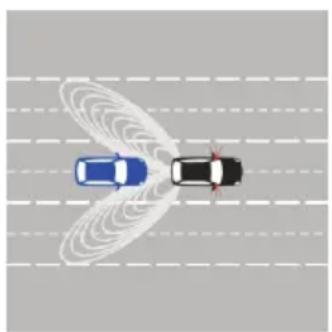
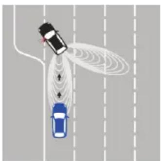
CAUTION
The SDA-BS900 can detect only objects approaching your vehicle from behind, but also detect objects your vehicle is approaching or overtaking. Under certain driving scenarios, the SDA-BS900 may detect objects in an unintended way. The following conditions below are examples of scenarios where fault notifications may occur.
natural_image
Top-down diagram of two cars with sensor waves on a road (no text or symbols)Fig 1
natural_image
Top-down illustration of a car with sensor waves interacting with a road, showing airflow patterns (no text or symbols)Fig 2

natural_image
Illustration of a fly and a car on a road with dashed lane lines (no text or symbols)Fig 3

natural_image
Top-down diagram of three cars on a road with visible motion trails (no text or symbols)Fig 4
System Indicators
A. When the system is turned on each time (your vehicle ignition or ACC is switched on), both LED indicators will flash once to indicate system start up and initialization. Once a GPS connection is established, which may take up to 2 minutes, both LED indicators will flash twice to indicate the system is ready for use. The GPS connection is used to calculate your vehicle's speed. When your vehicle is traveling slower than the start speed setting 18mph(29km/h), the system will not produce warnings.
B. Blind spot detection toward the right rear of your vehicle:
- The Right LED indicator will illuminate and remain illuminated when there is an object or vehicle approaching, or when your vehicle approaches and passes a moving vehicle.
- If your vehicle's right turn signal is activated when there is an object or vehicle approaching, or when your vehicle approaches and passes a moving vehicle, the Right LED indicator will flash repeatedly and the included speaker will beep (bi-bi-bi) one time
C. Blind spot detection toward the left rear of your vehicle:
- The Left LED indicator will illuminate and remain illuminated when there is an object or vehicle approaching, or when your vehicle approaches and passes a moving vehicle.
- If your vehicle's left turn signal is activated when there is an object or vehicle approaching, or when your vehicle approaches and passes a moving vehicle, the Left LED indicator will flash repeatedly and the included speaker will beep (bi-bi-bi) one time
D. Cross-Traffic Detection:
-
When your vehicle is reversing and the system detects an object or vehicle approaching from your right, the right LED indicator will illuminate and remain illuminated and the included speaker will beep repeatedly.
-
When your vehicle is reversing and the system detects an object or vehicle approaching from your left, the Left LED indicator will illuminate and remain illuminated and the included speaker will beep repeatedly.
Note: The system will not detect or warn of standing objects or objects moving under 5 mph (8 km/h).
Item List
| Number | Item Name | Quantity | Pictures |
| 1 | Radar sensor | 2 PC |  |
| 2 | Main Harness | 1 SET | 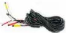 |
| 3 | LED Extension Cable | 1 SET | 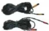 |
| 4 | GPS Tieline | 1 PC |  |
| 5 | LED Indicators | 1 SET | 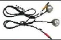 |
| 6 | Extra LED Indicator Lens and Double Sided Tape | 2 SET | 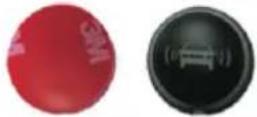 |
| 7 | GPS Antenna | 1 PC | 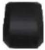 |
| 8 | Speaker | 1 PC | 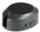 |
| 9 | Installation Angle Tool | 1 PCS |  |
| 10 | Drill Bit, Rivets and Mounting bracket | Drill 1PC& Rivets 12PCS Mounting Bracket 1SET | 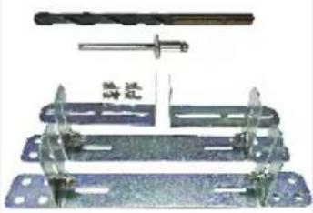 |
Required tools for installation: Insulation tape; Multi-meter; Screwdriver; Cleaning cloth; ;Drill Bit Rivets; Mounting bracket, electric drill ; Rivet gun; Clamps; Pry Tools.
Installation Diagram

Note: If you cannot connect to the rear tail lamp (turn signal lights combined with brake lights), then connect at the front fuse box.
Wire Connection Diagra

flowchart
graph TD
    A["Left sensor"] --> B["GPS Antenna"]
    C["Right sensor"] --> D["FUSE (2 A)"]
    B --> E["Left LED indicator"]
    D --> F["Right LED indicator"]
    E --> G["Speaker"]
    F --> G
    style A fill:#000,stroke:#fff,color:#fff
    style C fill:#000,stroke:#fff,color:#fff
    style B fill:#000,stroke:#fff,color:#fff
    style D fill:#000,stroke:#fff,color:#fff
    style E fill:#000,stroke:#fff,color:#fff
    style F fill:#000,stroke:#fff,color:#fff
    style G fill:#000,stroke:#fff,color:#fff
    note1["① Left sensor cable - 1.1"]
    note2["② Right sensor cable - 1.3"]
    note3["③ Left sensor connector"]
    note4["④ Right sensor connection"]
    note5["⑤ Sensor extension cable"]
    note6["⑥ Main connector cable"]
    note7["⑦ GPS circuit board"]
    note8["⑧ Left LED extension cable"]
    note9["⑨ Right LED extension cable"]
    note10["⑩ Speaker cable - 10.5"]
    note11["⑪ Green reverse trigger"]
    note12["⑫ Pink left-turn signal t"]
    note13["⑬ Orange right-turn sig 7.5 ft (230 cm)"]
    note14["⑭ Black GND - 7.5 ft (23"]
    note15["⑮ Red ACC/IGN - 15.7 ft"]
    note16["⑯ GPS antenna - 10.5 ft"]
    note17["⑰ Red Left LED indicator"]
    note18["⑱ Yellow Right LED indi"]
    note19["If cannot be connected to signal lights maybe com then connect at the front"]
English
① Left sensor cable - 1.6 ft (50 cm)
② Right sensor cable - 1.6 ft (50 cm)
③ Left sensor connector - 5.5 ft (170 cm)
④ Right sensor connector - 5.5 ft (170 cm)
⑤ Sensor extension cable - 16.4 ft (500 cm)
⑥ Main connector cables - 1.4 ft (45 cm)
⑦ GPS circuit board cable - 1.3 ft (40cm)
⑧ Left LED extension cable - 22.9 ft (700 cm)
⑨ Right LED extension cable - 22.9 ft (700 cm)
⑩ Speaker cable - 10.5 ft (320 cm)
⑪ Green reverse trigger wire - 7.5 ft (230 cm)
⑫ Pink left-turn signal trigger wire - 7.5 ft (230 cm)
⑬ Orange right-turn signal trigger wire - 7.5 ft (230 cm)
⑭ Black GND - 7.5 ft (230 cm)
⑮ Red ACC/IGN - 15.7 ft (480 cm)
⑯ GPS antenna - 10.5 ft (320 cm)
⑰ Red Left LED indicator cable - 1.6 ft (50 cm)
⑱ Yellow Right LED indicator cable - 1.6 ft (50 cm) If cannot be connected to rear tail lamp (turn signal lights maybe combined with brake lights) then connect at the front fuse box.
Installation Guide
WARNING
- For professional installation only by personnel with specialized training and experience in mobile electronics.
- Do not install the LED Indicators where it may (i) obstruct the driver's vision, (ii) impair the performance of any of the vehicle's operating systems or safety features, including air bags or hazard lamp buttons or (iii) impair the driver's ability to safety operate the vehicle.
- Never install this product in front of or next to the place in the dashboard, door, or pillar from which one of your vehicle's airbags would deploy. Please refer to the vehicle's owner's manual for reference to the deployment area of the airbags.
- Secure all wiring with cable clamps or electrical tape. Do not allow any bare wiring to remain exposed.
• Make sure that the cables and wires will not interfere with or become caught in any of the vehicle's moving parts, especially brake, doors, or any of the vehicle's controls. - If the wiring of this unit is located under a front seat, make sure it does not obstruct seat movement. Route all leads and cords carefully around the sliding mechanism so they do not get caught or pinched in the mechanism and cause a short circuit.
- Do not shorten any leads. If you do, the protection circuit (fuse holder, fuse resistor or filter, etc.) may fail to work properly.
- When replacing the fuse, be sure to use a fuse only of the rating prescribed on this product.
- Use only the parts included with the unit to ensure proper installation. The use of unauthorized parts can cause malfunctions.
- Never feed power to other electronic products by cutting the insulation of the power supply lead of this product and tapping into the lead. The current capacity of the lead will be exceeded, causing overheating.
- Use this unit with a 12-volt battery and negative grounding only. Failure to do so may result in a fire or malfunction.
- The graphical symbol placed on the product means direct current.
- Disconnect the negative terminal of the battery before installation.
- Secure the wiring with cable clamps or adhesive tape. Wrap adhesive tape around wiring that comes into contact with metal parts to protect the wiring.
- Do not perform installation in rain or fog.
CAUTION
- Ensure that the connector is inserted correctly and according to the corresponding label and the arrow marks of the wire connector at the connection point. When connecting, ensure that the KEY or raised area of the connector mates with the opposite connector. Do not force any connection and ensure that the connector mates properly.
• To avoid any damage to the connectors, align the arrows on each of the corresponding items, then firmly press connectors together to ensure a good connection. Failure to properly install and connect the system components may cause damage to the product and operation of the system.
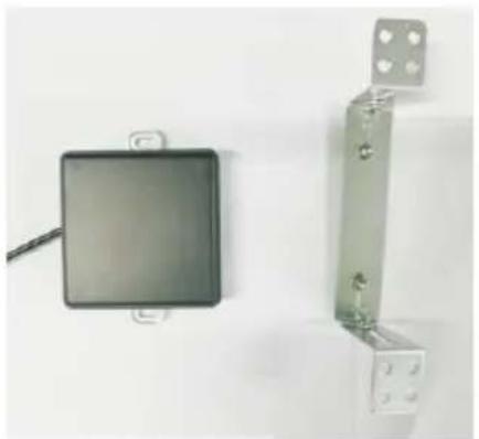
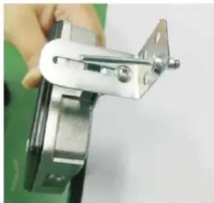
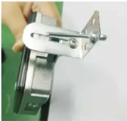
Step 1: Sensor heads Installation
Mounting Radar Pucks with Provided Adjustable Brackets:
1) Prepare Materials brackets and radar heads (see Fig 5).
2) Mount the sensor module on the bracket with screws of the assemble bag (see Fig 6).
3) After found angle is set, firmly screw or bolt the bracket to the car (see Fig 7).
natural_image
Two wall-mounted electronic components: a black square sensor and a metallic bracket with mounting holes (no text or symbols visible)Fig 5

natural_image
Close-up of a black square electronic component mounted on a metal frame with a cable, against a plain white background (no text or symbols visible)Fig 6
natural_image
Close-up of a hand holding a metallic mechanical clamp or bracket (no visible text or symbols)Fig 7
Use Supplied Tool to Set Proper Radar Puck Angle: the default installation angle is: 38 degree. Depending on actual situation, the install angle could be adjusted accordingly.
Please following installation guide view to installed the sensors as below:
Two sensors will respectively installed the vehicle rear left and right corner parts, in the bumper (see Fig 8).
Height of sensor installation should be between the lowest line of tail lights and the highest line of fog lights (see Fig 9).
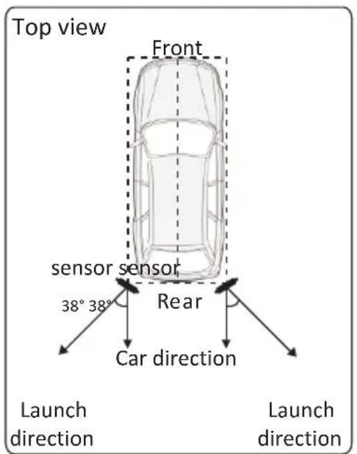
Fig 8
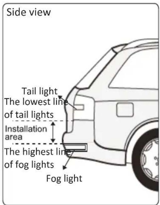
Fig 9
Please see illustration below, for correct guidance and mounting position of sensors with angle tool (see Fig 10, Fig 11).
Note: Place the flat side of angle tool on the front of the sensor head, align the arrow of the angle tool to point towards the back of the vehicle (see Fig10, Fig 11).
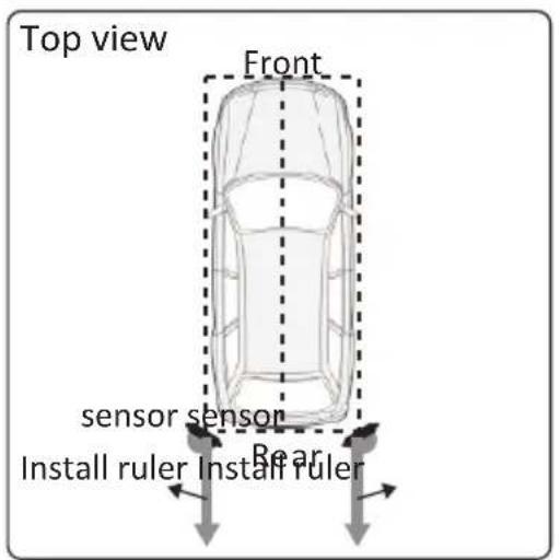
Fig 10
natural_image
Line drawing of a car interior showing the engine compartment and dashboard (no text or symbols)Fig 11
When installing the sensor, keep the metal back side close to the mounting surface, keep both sides of the sensor perpendicular to the ground (see Fig 12).
To make sure the sensor is correctly oriented, make sure the wire is exiting from the left/right side of the sensor specific to their mounting side. The sensor should be installed as shown in the figure below (The cable can be routed on the top or bottom of the sensor as shown in the figure below, but do not route the cable in front of the sensor surface) (see Fig 13, Fig 14, Fig 15, Fig 16, Fig 17).

Fig 12

Fig 13

Fig 14
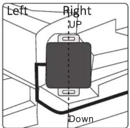
Fig 15
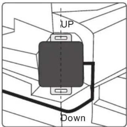
Fig 16

Fig 17
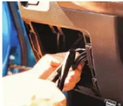
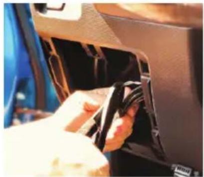
Step 2: Left/Right Turn Signal Installation
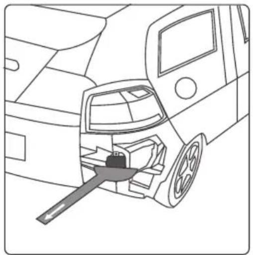
Using a voltage multi-meter, locate the isolated left and isolated right turn signal trigger wires, commonly found behind the vehicle's left and right tail lamp assemblies. If turn signal lights are combined with brake lights, then connect the turn signal trigger wires at the front fuse box.
Once verified, connect the left and right turning signal wires to the appropriate corresponding input wires of the SDA-BS900 wire harness (see Fig 18, Fig 19, Fig 20). Turn signal inputs of SDA-BS900 is +12VDC only (not switchable to -12VCD); please check with a voltage multi-meter.

natural_image
Top-down view of a blue car trunk cab with open rear compartment (no visible text or symbols)Fig 18

natural_image
Close-up of a car's dashboard control knob showing settings like END, 34T, and 5+ (no readable text or symbols beyond basic labels)Fig 19
natural_image
Close-up of a hand inserting a black plastic bag into a car interior (no visible text or symbols)Fig 20
Step 3: LED Indicator Installation
Install the Left LED indicator and Right LED indicator in a location that is visible to the driver, ideally in or around the vehicle's A-pillars (see Fig 21, Fig 22). Place the LED indicators away from the side curtain air bags, so as not to hinder the deployment of airbag function. Appropriate placement is usually at the lowest part of the A-pillars, but you must consult the vehicle manual.

natural_image
Close-up of a car's front window with a hand adjusting the lid panel (no visible text or symbols)Fig 21

natural_image
Close-up of a hand cleaning a car door panel, no visible text or symbolsFig 22
NOTE:
• Changing the LED housing color
The system includes two options for the LED indicator housing. Depending on the customer's choice and/or vehicle's interior color, you may change the LED cover from grey (default) to black.
- First peel back 3M ^® tape from the LED indicator housing.
- Using a small flat head screwdriver, remove the cover.
- Align wire notch from the new cover, and snap into place.
- Use the supplied 3M tape and re-apply behind LED.
Step 4: Speaker Installation
While installing the speaker, make sure it is not obstructed by any panels inside the vehicle(see Fig 23).
NOTE:
To adjust volume on the speaker, toggle the switch to the desired setting, "HI/LOW/OFF".

natural_image
Close-up of a car seatbelt component with a metallic knob (no visible text or symbols)Fig 23
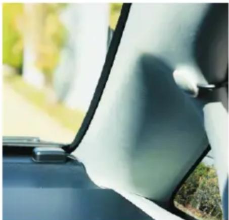
Step 5: GPS Antenna Installation
When installing the GPS Antenna, make sure it is not obstructed by any panels inside the vehicle (see Fig 24).
natural_image
Close-up of a car's front window and side door, showing white plastic sheeting and green grass near the window (no text or symbols visible)Fig 24
Step 6: Wires Installation
Soldering all wiring is recommended. Securely tape and insulate all connections soldered.
- Secure all wires neatly to hide and prevent wire pinch.
- +12 VDC ACC/IGN - Locate the +12 VDC (ACC/IGN) and connect the red wire from the Main harness.
- Chassis Ground (Black) - Connect the black wire from the Main harness to chassis ground.
- +12 VDC reverse signal (Green) - Locate the +12 VDC reverse signal (reverse light or other location) and connect the green wire from the Main harness.
- Orange Right-Turn signal Trigger - Locate the +12 VDC Isolated turn signal and connect the Right (Orange) wire from the Main harness.
- Pink Left-Turn Signal Trigger - Locate the +12 VDC Isolated turn signal and connect the Left (Pink) wire from the Main harness.
- Connect the Main harness into the sensors.
- Make all the appropriate connections (LED's, Speaker, sensors) on the Main harness.
- Connect the negative terminal of the battery to the vehicle.
- Test the system's operation, ensuring that all features operate according to this manual. After operation is tested, finalize connections and secure wires.
Technical Specifications
| 70 degrees ( ) HorizontalDetection Range | |
| Speed Range 0.5 mph (-36 km/h) 37 mph (60 km/h) ~ | |
| Speed Accuracy | < 0.5 mph (0.8 km/h) |
| Direction of Movement | Approached by vehicles, Following by vehicles, Overtaking vehicles |
| Detection Range | -6.5 ft (-2 m) ~ 82ft (25m) |
| Operating Voltage | 9~18V |
| Waterproof | Radar sensor: IPX6/IPX7Other items such as cables: NOT waterproof |
| Working Current | 400mA |
| Working Temperature | -40°F ~ 185°F (-40°C ~ 85°C) |
| FUSE rating value | 2 A |
| Speed Restriction | The system will activate the sensors once the vehicle reaches a speed above 18mph(29km/h). |
Troubleshooting
| NO. | Issues | Reasons | Solutions |
| 1 | LED light does not work | Incorrect connection or pins not making contact | Check the harness and make sure connection is correct |
| LED light is broken Replace LED | light | ||
| 2 | Opposite LED indicator | Microwave sensor or LED indicators are plugged in to the opposite connector | Make sure the LED indicator with RED color is on driver side and YELLOW is on the passenger side, also the sensor with RED color is on driver side YELLOW is on the passenger sideMake sure the signal wires are connecting correctly |
| 3 | Speaker does not work | Wrong connection or pins not making contact | Check the harness and make sure connection is correct |
| Defective Speaker | Replace Speaker | ||
| 4 | Sensor or GPS does not work | Sensor or GPS Antenna module is covered by the metal bumper or other metal | Find the best location where the sensor or GPS Antenna cannot be blocked by any metal |
| 5 | Unit does not work | Blind spot system does not trigger the sensor if the speed is less than 18 mph (29 km/h) | Keep the speed of your vehicle higher than 18 mph (29 km/h) |
| 6 | FUSE is blown | Over current / Power surge Exchange FUSE (2 A) | |
| 7 | Blind area object detection not consistent or unstable | Not Installed correct location | Find the correct location to install Find the location where the radar sensing area is not blocked by objects(s) |
| Installed with wrong angle (pointing upward) | |||
| Installed at a location with object in front | |||
SDA-BS900
DÉTECTION DES ANGLES MORTS / SYSTÈME D'ASSISTANCE AU CHANGEMENT DE VOIE
URL: http://www.pioneerelectronics.com
Pioneer Electronics (USA) Inc.
SERVICE À LA CLIENTÈLE
P.O. Box 1720 Long Beach, CA 90801-1720
Pioneer Electronics (USA) Inc.
P.O. Box 1720, Long Beach, California 90801 U.S.A.
natural_image
Four-panel illustration showing a car with sensor waves interacting on a road, including a fly and a drone (no text or symbols)natural_image
Two electronic components: a black square sensor and a metallic bracket with four holes (no text or symbols visible)Fig.5

natural_image
Close-up of a black square electronic component mounted on a metal bracket with mounting holes (no visible text or symbols)Fig. 6
natural_image
Close-up of a hand holding a metallic mechanical clamp or bracket (no visible text or symbols)Fig. 7
natural_image
Line drawing of a car interior showing a hand tool inserted into the dashboard (no text or symbols)Fig. 11
natural_image
Top-down view of a blue car trunk with open lid and internal compartments (no visible text or symbols)Fig. 18

natural_image
Close-up of a car headrest lever with rotary knob (no visible text or symbols)Fig. 19
natural_image
Close-up of a hand inserting a black plastic component into a car interior (no visible text or symbols)Fig. 20
natural_image
Close-up of a car's front window showing the lid and side panel, with a hand adjusting the panel (no visible text or symbols)Fig. 21

natural_image
Close-up of hands cleaning a car's door panel, no visible text or symbolsFig. 22
NOTE:
natural_image
Close-up of a car seatbelt with a metallic knob (no visible text or symbols)Fig. 23
natural_image
Close-up of a car's side window showing the roof and window frame, with blurred greenery in the background (no text or symbols visible)Fig. 24
PIONEER ELECTRONICS (USA) INC.
P.O. Box 1540, Long Beach, California 90801-1540, U.S.A.
TEL: (800) 421-1404


- Important (Serial number)
- Contents
- ■ Precaution....3
- Precaution
- Information to Customer
- Information to User
- - Special vehicle conditions that should be considered
- - Situations that cannot be detected
- Situations that may affect system detection accuracy
- Important Safety Information
- WARNING
- After-Sales Service
- Three Year Limited Warranty
- Customer Support:
- Visit our Website
- Alert Conditions
- CAUTION
- System Indicators
- Item List
- Installation Diagram
- Wire Connection Diagra
- Installation Guide
- Step 1: Sensor heads Installation
- Mounting Radar Pucks with Provided Adjustable Brackets:
- Step 2: Left/Right Turn Signal Installation
- Step 3: LED Indicator Installation
- NOTE:
- Step 4: Speaker Installation
- Step 5: GPS Antenna Installation
- Step 6: Wires Installation
- Technical Specifications
- Troubleshooting
- SDA-BS900
- PIONEER ELECTRONICS (USA) INC.
Brand : PIONEER
Model : SDABS900
Category : Dashcam