
K 7000 - Saw HUSQVARNA - Free user manual and instructions
Find the device manual for free K 7000 HUSQVARNA in PDF.

| Product Type | Electric hand-held cut-off saw |
| Brand | Husqvarna |
| Model | K 7000 / K 7000 SmartGuard |
| Intended Use | Cutting of hard materials: concrete, brick, stone, steel |
| Motor | High frequency (HF), three-phase or single-phase |
| Maximum Power (three-phase) | 5.5 kW |
| Maximum Power (single-phase) | 3 kW |
| Supply Voltage | 120-240 V |
| Max Spindle Speed | 4,300 rpm |
| Max Blade Diameter | 400 mm (16 in) |
| Max Cutting Depth | 155 mm (6 in) |
| Weight (without blade and cable) | 9.8 kg (K 7000) / 10.8 kg (SmartGuard) |
| Weight of Cable | 1.9 kg |
| Cooling | Water (recommended pressure 0.5-8 bar) |
| Sound Power Level | 104 dB(A) |
| Sound Pressure Level | 93 dB(A) |
| Vibrations (front handle) | 1.8 m/s² |
| Vibrations (rear handle) | 1.6 m/s² |
| Anti-Vibration System | Yes |
| Overload Protection | Elgard™ (electronic) |
| Safety Devices | Trigger lock, blade guard, SmartGuard (optional) |
| Required Protective Equipment | Helmet, ear protection, safety glasses, gloves, respiratory protection |
| Daily Maintenance | External cleaning, checking safety devices |
| Belt Tension | Adjustable via adjusting screw, mark on cover |
| Spare Parts | Use only genuine Husqvarna parts |
| Warranty / Compliance | CE, RoHS, Machinery Directive 2006/42/EC |
| Manufacturer | Husqvarna AB, SE-561 82 Huskvarna, Sweden |
Frequently Asked Questions - K 7000 HUSQVARNA
User questions about K 7000 HUSQVARNA
0 question about this device. Answer the ones you know or ask your own.
Ask a new question about this device
Download the instructions for your Saw in PDF format for free! Find your manual K 7000 - HUSQVARNA and take your electronic device back in hand. On this page are published all the documents necessary for the use of your device. K 7000 by HUSQVARNA.
USER MANUAL K 7000 HUSQVARNA
K 7000, K 7000 SmartGuard
EN Operator's manual 2-31
Transportation, storage and disposal.... 27
Technical data.... 28
Declaration of Conformity.... 30
Introduction
Product description
These HUSQVARNA K 7000 and K 7000 SmartGuard are electric portable handheld cut-off machines. To operate the product, connect the product to the necessary power pack.
Intended use
The product is used to cut hard materials as concrete, masonry, stone and steel. Do not use the product for
other tasks. The product must only be used by professional operators with experience.
Work is constantly in progress to increase your safety and efficiency during operation. Speak to your servicing dealer for more information.
Note: National/Local regulations could restrict the use of this product.
Product overview K 7000
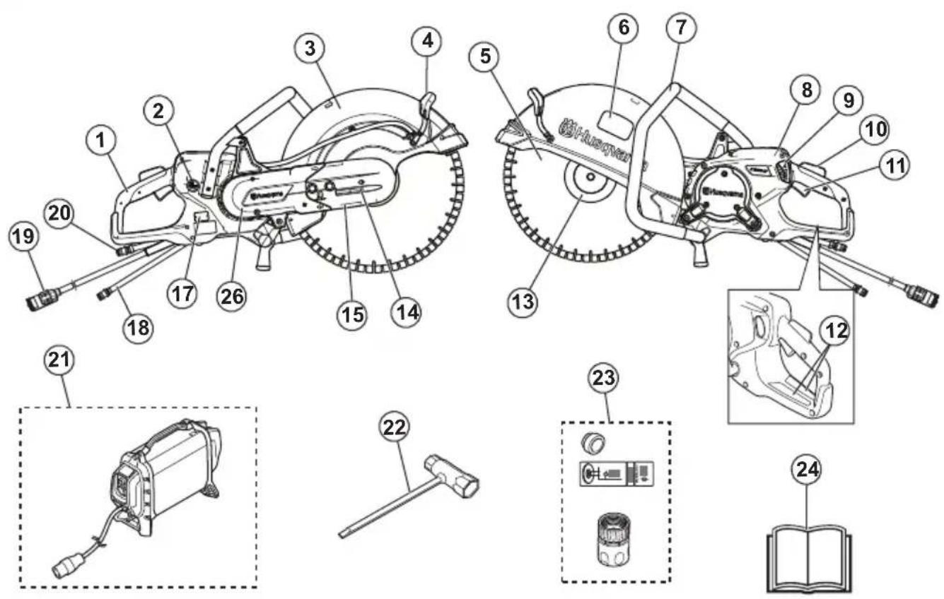
- Rear handle
- Switch for water supply
- Blade guard
- Adjustment handle for the blade guard
- Cutting blade (not supplied)
- Cutting equipment decal
-
Front handle
-
Display
- Water flow adjustment valve
- Power trigger lockout
- Power trigger
- Information and warning decal
- Flange, spindle and arbor bushing
-
Belt tensioner
-
Front belt guard
- Rear belt guard
- Type plate
- Water connection with filter, inlet
- Power pack connection
-
Water connection, outlet (return hose)
-
HUSQVARNA high frequency power pack, (necessary, not supplied)
- Combination wrench
- Bushing, decal and water connector
- Operator's manual
Product overview K 7000 SmartGuard
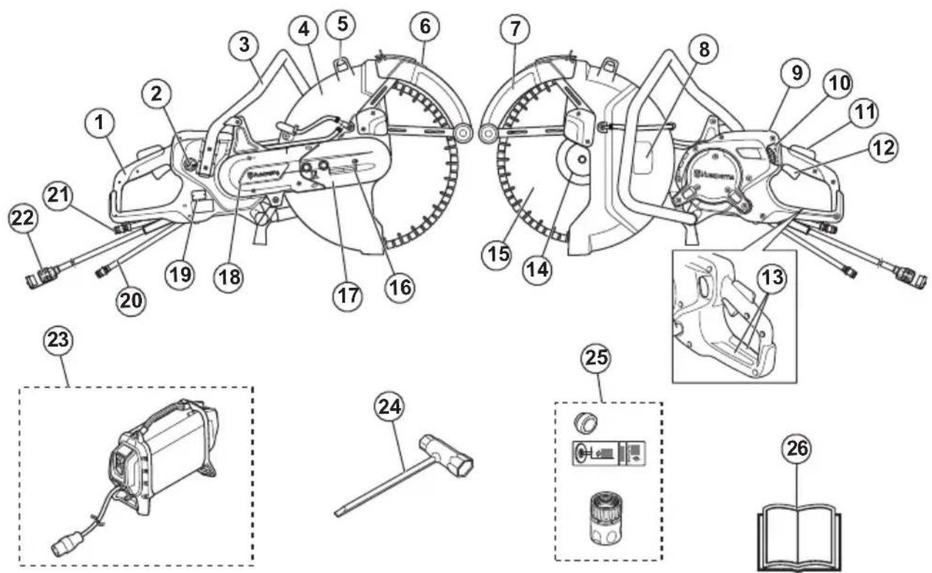
- Rear handle
- Switch for water supply
- Front handle
- Blade guard
- Adjustment handle for the blade guard
- SmartGuard handle
- SmartGuard
- Cutting equipment decal
- Display
- Water flow adjustment valve
- Power trigger lockout
- Power trigger
- Information and warning decal
- Flange, spindle and arbor bushing
- Cutting blade (not supplied)
- Belt tensioner
- Front belt guard
- Rear belt guard
-
Type plate
-
Water connection with filter, inlet
- Water connection, outlet (return hose)
- Power pack connection
- HUSQVARNA high frequency power pack, (necessary, not supplied)
- Combination wrench
- Bushing, decal and water connector
- Operator's manual
Symbols on the product

WARNING: This product can be dangerous and cause serious injury or death to the operator or others. Be careful and use the product correctly.

Read the operator's manual carefully and make sure that you understand the instructions before you use this product.

Use approved protective helmet, hearing protection, eye protection and respiratory protection. Refer to Personal protective equipment on page 8.
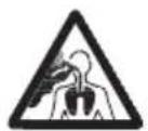
Dust forms when cutting. The dust can cause injuries if inhaled. Use an approved respiratory protection. Always provide for good ventilation.
Sparks from the cutting blade can cause fire in fuel, wood, clothes, dry grass or other flammable materials.
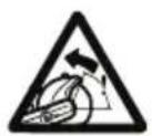
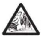
WARNING! Kickbacks can be sudden, rapid and violent and can cause life threatening injuries. Read and understand the instructions in the manual before using the product. Refer to Kickback on page 17.

Make sure that the cutting blade does not have cracks or other damages.

Do not use circular saw blades.

This product complies with applicable EU Directives.
Environmental mark. The product or package of the product is not domestic waste. Recycle it at a recycling location for electrical and electronic equipment.
Note: Other symbols/decals on the product refer to certification requirements for some markets.
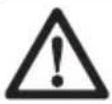
Cutting equipment decal
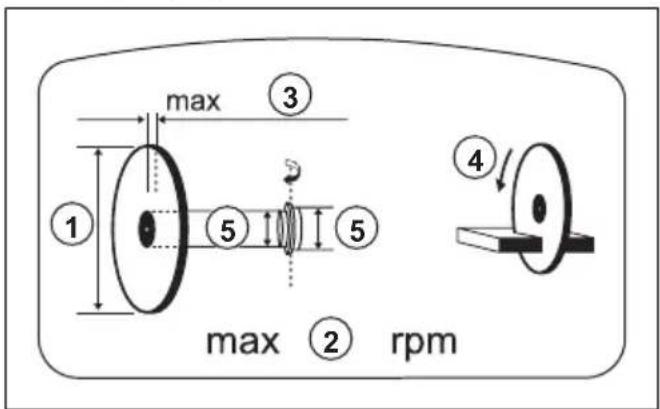
- Cutting blade diameter
- Max. speed of output shaft
- Max. blade thickness
- Direction of rotation
- Bushing dimension
Type plate
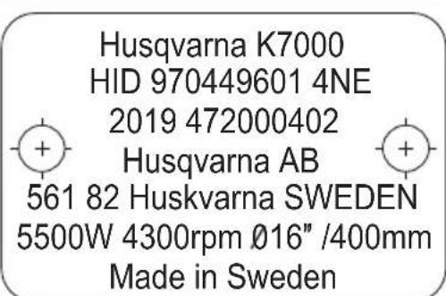
Row 1: Brand, Model
Row 2: Product id
Row 3: Manufacturing year, Serial No
Row 4: Manufacturer
Row 5: Manufacturer address
Row 6: Output power, Cutting blade rpm, Blade capacity
Row 7: Country of origin
Product liability
As referred to in the product liability laws, we are not liable for damages that our product causes if:
• the product is incorrectly repaired.
• the product is repaired with parts that are not from the manufacturer or not approved by the manufacturer.
• the product has an accessory that is not from the manufacturer or not approved by the manufacturer.
- the product is not repaired at an approved service center or by an approved authority.
Safety
Safety definitions
Warnings, cautions and notes are used to point out specially important parts of the manual.

WARNING: Used if there is a risk of injury or death for the operator or bystanders if the instructions in the manual are not obeyed.

CAUTION: Used if there is a risk of damage to the product, other materials or the adjacent area if the instructions in the manual are not obeyed.
Note: Used to give more information that is necessary in a given situation.
General power tool safety warnings

WARNING: Read all safety warnings and all instructions. Failure to follow the warnings and instructions may result in electric shock, fire and/or serious injury.
Note: Save all warnings and instructions for future reference. The term "power tool" in the warnings refers to your mains-operated (corded) power tool or battery-operated (cordless) power tool.
Work area safety
- Keep work area clean and well lit. Cluttered or dark areas invite accidents.
- Do not operate power tools in explosive atmospheres, such as in the presence of flammable liquids, gases or dust. Power tools create sparks which may ignite the dust or fumes.
- Keep children and bystanders away while operating a power tool. Distractions can cause you to lose control.
Electrical safety
- Power tool plugs must match the outlet. Never modify the plug in any way. Unmodified plugs and matching outlets will reduce risk of electric shock.
- Avoid body contact with earthed or grounded surfaces, such as pipes, radiators, ranges and refrigerators. There is an increased risk of electric shock if your body is earthed or grounded.
-
Do not expose power tools to rain or wet conditions. Water entering a power tool will increase the risk of electric shock.
-
Do not abuse the cord. Never use the cord for carrying, pulling or unplugging the power tool. Keep cord away from heat, oil, sharp edges or moving parts. Damaged or entangled cords increase the risk of electric shock.
- When operating a power tool outdoors, use an extension cord suitable for outdoor use. Use of a cord suitable for outdoor use reduces the risk of electric shock.
- If operating a power tool in a damp location is unavoidable, use a residual circuit interrupter (RCD) protected supply. Use of a RCD reduces the risk of electric shock
CAUTION: Do not pressure wash the machine, as water can enter the electrical system or the motor and cause damage to the machine or short circuit.
Personal safety
- Stay alert, watch what you are doing and use common sense when operating a power tool. Do not use a power tool while you are tired or under the influence of drugs, alcohol or medication. A moment of inattention while operating power tools may result in serious personal injury.
- Use personal protective equipment. Always wear eye protection. Protective equipment such as dust mask, non-skid safety shoes, hard hat, or hearing protection used for appropriate conditions will reduce personal injuries.
- Prevent unintentional starting. Ensure the switch is in the OFF-position before connecting to a power source and/or battery pack, picking up or carrying the tool. Carrying power tools with your finger on the switch or energizing power tools that have the switch on invites accidents.
- Remove any adjusting key or wrench before turning the power tool on. A wrench or a key left attached to a rotating part of the power tool may result in personal injury.
- Do not overreach. Keep proper footing and balance at all times. This enables better control of the power tool in unexpected situations.
- Dress properly. Do not wear loose clothing or jewellery. Keep your hair, clothing and gloves away from moving parts. Loose clothes, jewellery or long hair can be caught in moving parts.
- If devices are provided for the connection of dust extraction and collection facilities, ensure these are connected and properly used. Use of dust collection can reduce dust-related hazards.
- Do not let familiarity gained from frequent use of tools allow you to become complacent and ignore
tool safety principles. A careless action can cause severe injury within a fraction of a second.
- The vibration emission during actual use of the power tool can differ from the declared total value depending on the ways in which the tool is used. Operators should identify safety measures to protect themselves that are based on an estimation of exposure in the actual conditions of use (taking account of all parts of the operating cycle such as the times when the tool is switched off and when it is running idle in addition to the trigger).
- Remain at a distance from the blade when the motor is running.
Power tool use and care
- Do not force the power tool. Use the correct power tool for your application. The correct power tool will do the job better and safer at the rate for which it was designed.
- Do not use the power tool if the switch does not turn it on and off. Any power tool that cannot be controlled with the switch is dangerous and must be repaired.
- Disconnect the plug from the power source and/or the battery pack from the power tool before making any adjustments, changing accessories, or storing power tools. Such preventive safety measures reduce the risk of starting the power tool accidentally.
- Store idle power tools out of the reach of children and do not allow persons unfamiliar with the power tool or these instructions to operate the power tool. Power tools are dangerous in the hands of untrained users.
- Maintain power tools. Check for misalignment or binding of moving parts, breakage of parts and any other condition that may affect the power tool's operation. If damaged, have the power tool repaired before use. Many accidents are caused by poorly maintained power tools.
- Keep cutting tools sharp and clean. Properly maintained cutting tools with sharp cutting edges are less likely to bind and are easier to control.
- Use the power tool, accessories and tool bits etc. in accordance with these instructions, taking into account the working conditions and the work to be performed. Use of the power tool for operations different from those intended could result in a hazardous situation.
- Keep handles and grasping surfaces dry, clean and free from oil and grease. Slippery handles and grasping surfaces do not allow for safe handling and control of the tool in unexpected situations.
-
Under no circumstances should you modify the original design of the machine without approval from the manufacturer. Always use original spare parts. Unauthorized modifications and/or accessories may lead to serious injury or death to the user or others.
-
Make sure that no pipes or electrical cables are routed in the working area or in the material to be cut.
• Always check and mark out where gas pipes are routed. Cutting close to gas pipes always entails danger. Make sure that sparks are not caused when cutting in view of the risk of explosion. Remain concentrated and focused on the task. Carelessness can result in serious personal injury or death.
Service
- Have your power tool serviced by a qualified repair person using only identical replacement parts. This will ensure that the safety of the power tool is maintained.
Cut-off machine safety warning
- The guard provided with the tool must be securely attached to the power tool and positioned for maximum safety so the least amount of wheel is exposed towards the operator. Position yourself and bystanders away from the plane of the rotating wheel. The guard helps to protect operator from broken wheel fragments and accidental contact with the wheel.
- Use only bonded reinforced or diamond cut-off wheels for your power tool. Just because an accessory can be attached to your power tool, it does not assure safe operation.
- The rated speed of the accessory must be at least equal to the maximum speed marked on the power tool. Accessories running faster than their rated speed can break and fly apart.
- Wheels must be used only for recommended applications. For example, do not grind with the side of the cut-off wheel. Abrasive cut-off wheels are intended for peripheral grinding, side forces applied to these wheels may cause them to shatter.
- Always use undamaged wheel flanges that are of correct diameter for your selected wheel. Proper wheel flanges support the wheel thus reducing the possibility of wheel breakage.
- Do not use worn down reinforced wheels from larger power tools. Wheels intended for a larger power tool are not suitable for the higher speed of a smaller tool and may burst.
- The outside diameter and the thickness of your accessory must be within the capacity rating of your power tool. Incorrectly sized accessories cannot be adequately guarded or controlled.
- The arbour size of wheels and flanges must properly fit the spindle of the power tool. Wheels and flanges with arbour holes that do not match the mounting hardware of the power tool will run out of balance, vibrate excessively and may cause loss of control.
- Do not use damaged wheels. Before each use, inspect wheels for chips and cracks. If power tool or wheel is dropped, inspect for damage or install an undamaged wheel. After inspecting and installing the
wheel, position yourself and bystanders away from the plane of the rotating wheel and run the power tool at maximum no load speed for one minute. Damaged wheels will normally break apart during this test time.
- Wear personal protective equipment. Depending on application, use face shield, safety goggles or safety glasses. As appropriate, wear dust mask, hearing protectors, gloves and shop apron capable of stopping small workpiece fragments. The eye protection must be capable of stopping flying debris generated by various operations. The dust mask or respirator must be capable of filtrating particles generated by your operation. Prolonged exposure to high intensity noise may cause hearing loss.
- Keep bystanders a safe distance away from work area. Anyone entering the work area must wear personal protective equipment. Fragments of workpiece or a broken wheel may fly away and cause injury beyond immediate area of operation.
- Hold the power tool by insulated gripping surfaces only, when performing an operation where the cutting accessory may contact hidden wiring. Cutting accessory contacting a "live" wire may make exposed metal parts of the power tool "live" and could give the operator an electric shock.
- Position the cord clear of the spinning accessory. If you lose control, the cord may be cut or snagged and your hand or arm may be pulled into the spinning wheel.
- Never lay the power tool down until the accessory has come to a complete stop. The spinning wheel may grab the surface and pull the power tool out of your control.
- Do not run the power tool while carrying it at your side. Accidental contact with the spinning accessory could snag your clothing, pulling the accessory into your body.
- Regularly clean the power tool's air vents. The motor's fan will draw the dust inside the housing and excessive accumulation of powdered metal may cause electrical hazards.
- Do not operate the power tool near flammable materials. Sparks could ignite these materials.
Kickback and related warnings
- Kickback is a sudden reaction to a pinched or snagged rotating wheel. Pinching or snagging causes rapid stalling of the rotating wheel which in turn causes the uncontrolled power tool to be forced in the direction opposite of the wheel's rotation at the point of the binding.
- For example, if an abrasive wheel is snagged or pinched by the workpiece, the edge of the wheel that is entering into the pinch point can dig into the surface of the material causing the wheel to climb out or kick out. The wheel may either jump toward or away from the operator, depending on direction of the wheel's movement at the point of pinching.
Abrasive wheels may also break under these conditions.
- Kickback is the result of power tool misuse and/or incorrect operating procedures or conditions and can be avoided by taking proper precautions as given below.
- Maintain a firm grip on the power tool and position your body and arm to allow you to resist kickback forces. Always use auxiliary handle, if provided, for maximum control over kickback or torque reaction during start-up. The operator can control torque reactions or kickback forces, if proper precautions are taken.
- Never place your hand near the rotating accessory. Accessory may kickback over your hand.
- Do not position your body in line with the rotating wheel. Kickback will propel the tool in direction opposite to the wheel's movement at the point of snagging.
- Use special care when working corners, sharp edges etc. Avoid bouncing and snagging the accessory. Corners, sharp edges or bouncing have a tendency to snag the rotating accessory and cause loss of control or kickback.
- Do not attach a saw chain, woodcarving blade, segmented diamond wheel with a peripheral gap greater than 10 mm or toothed saw blade. Such blades create frequent kickback and loss of control.
- Do not "jam" the wheel or apply excessive pressure. Do not attempt to make an excessive depth of cut. Overstressing the wheel increases the loading and susceptibility to twisting or binding of the wheel in the cut and the possibility of kickback or wheel breakage.
- When wheel is binding or when interrupting a cut for any reason, switch off the power tool and hold the power tool motionless until the wheel comes to a complete stop. Never attempt to remove the wheel from the cut while the wheel is in motion otherwise kickback may occur. Investigate and take corrective action to eliminate the cause of wheel binding.
- Do not restart the cutting operation in the workpiece. Let the wheel reach full speed and carefully re-enter the cut. The wheel may bind, walk up or kickback if the power tool is restarted in the workpiece.
- Support panels or any oversized workpiece to minimize the risk of wheel pinching and kickback. Large workpieces tend to sag under their own weight. Supports must be placed under the workpiece near the line of cut and near the edge of the workpiece on both sides of the wheel.
- Use extra caution when making a “pocket cut” into existing walls or other blind areas. The protruding wheel may cut gas or water pipes, electrical wiring or objects that can cause kickback.
General safety instructions
WARNING: Read the warning instructions that follow before you use the product.
- A power cutter is a dangerous tool if used carelessly or incorrectly and can cause serious injury or death. It is very important that you read and understand the contents of this operator's manual. It is also recommended that first time operators also obtain practical instruction before using the product.
- Do not do modifications to this product. Modifications that are not approved by the manufacturer, can cause serious injury or death.
- Do not operate the product if it is possible that other persons have done modifications to the product.
• Always use original accessories and spare parts. Accessories and spare parts that are not approved by the manufacturer, can cause serious injury or death. - Keep the product clean. Make sure that you can clearly read signs and decals.
- Never allow children or other persons not trained in the use of the product to use or service it.
- Do not let a person operate the product unless they read and understand the contents of the operator's manual.
- Only let approved persons operate the product.
- This product produces an electromagnetic field during operation. This field can under some circumstances interfere with active or passive medical implants. To decrease the risk of serious injury or death, we recommend persons with medical implants to speak to their physician and the medical implant manufacturer before operating this product.
• The information in this operator's manual is never a substitute for professional skills and experience. If you are in a situation where you feel unsafe, stop and get expert advice. Speak to your servicing dealer. Do not try any task that you feel unsure of.
Safety instructions for operation

WARNING: Read the warning instructions that follow before you use the product.
- Before you use a power cutter, you must understand the effects of kickback and how to prevent them. Refer to Kickback on page 17.
- Do the safety checks, maintenance and servicing as given in this operator's manual. Some maintenance and servicing must be done by an approved service center. Refer to Safety instructions for maintenance on page 12.
-
Do not use the product if it is defective.
-
Do not use the product if you are tired, ill, or under the influence of alcohol, drugs or medicine. These conditions can have an unwanted effect on your vision, alertness, coordination or judgment.
- Do not start the product without the belt and the belt guard installed. The clutch can become loose and cause injury.
- Sparks from the cutting blade can cause fire in flammable materials such as gasoline, gas, wood, clothes and dry grass.
- Do not cut asbestos material.
Personal protective equipment
WARNING: Read the warning instructions that follow before you use the product.
• Always use approved personal protective equipment during operation. Personal protective equipment cannot eliminate the risk of injury but it will reduce the degree of injury if an accident does happen. Ask your servicing dealer for help in choosing the right equipment.
- Use an approved protective helmet.
- Use approved hearing protection. Long-term exposure to noise can result in permanent hearing impairment. Be aware of warning signals or shouts when you are wearing hearing protection. Always remove your hearing protection as soon as the motor stops.
- Use approved eye protection to decrease the risk of injury from thrown objects. If you use a face shield then you must also wear approved protective goggles. Approved protective goggles must comply with standard ANSI Z87.1 in the USA or EN 166 in EU countries. Visors must comply with standard EN 1731.
- Use heavy duty gloves.
- Use approved respiratory protection. The use of products such as cutters, grinders, drills, that sand or form material can generate dust and vapours which may contain hazardous chemicals. Check the nature of the material you intend to process and use appropriate breathing mask.
- Use tight-fitting, heavy-duty and comfortable clothing that permits full freedom of movement. Cutting generates sparks that can ignite clothing. HUSQVARNA recommends that you wear flame-retardant cotton or heavy denim. Do not wear clothing made of material such as nylon, polyester or rayon. If ignited such material can melt and cling to the skin. Do not wear shorts.
- Use boots with steel toe-cap and non-slip sole.
• Always keep a first aid kit near.
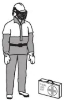
natural_image
Illustration of a person wearing full-body protective gear and a first aid kit (no text or symbols)- Sparks can come from the cutting blade. Always have a fire extinguishing available.
Vibration safety
WARNING: Read the warning instructions that follow before you use the product.
- During operation of the product, vibrations go from the product to the operator. Regular and frequent operation of the product can cause or increase the degree of injuries to the operator. Injuries can occur in fingers, hands, wrists, arms, shoulders, and/or nerves and blood supply or other body parts. The injuries can be debilitating and/or permanent, and can increase gradually during weeks, months or years. Possible injuries include damage to the blood circulation system, the nervous system, joints, and other body structures.
- Symptoms can occur during operation of the product or at other times. If you have symptoms and continue to operate the product, the symptoms can increase or become permanent. If these or other symptoms occur, get medical aid:
- Numbness, loss of feeling, tingling, pricking, pain, burning, throbbing, stiffness, clumsiness, loss of strength, changes in skin color or condition.
- Symptoms can increase in cold temperatures. Use warm clothing and keep your hands warm and dry when you operate the product in cold environments.
- Do maintenance on and operate the product as given in the operator's manual, to keep a correct vibration level.
- The product has a vibration damping system that decreases the vibrations from the handles to the operator. Let the product do the work. Do not push the product with force. Hold the product at the handles lightly, but make sure that you control the product and operate it safely. Do not push the handles into the end stops more than necessary.
- Keep your hands on the handle or handles only. Keep all other body parts away from the product.
- Stop the product immediately if strong vibrations suddenly occurs. Do not continue the operation
before the cause of the increased vibrations is removed.
- To cut granite or hard concrete causes more vibration in the product than if you cut soft concrete. Cutting equipment that is blunt, defective, of incorrect type or incorrectly sharpened, increases the vibration level
Safety devices on the product

WARNING: Read the warning instructions that follow before you use the product.
- Do not use a product with defective safety devices.
- Do a check of the safety devices regularly. If the safety devices are defective, speak to your HUSQVARNA approved service agent.
- Do not change the safety devices.
- Do not use the product if protective plates, protective covers, safety switches or other protective devices are defective or not attached.
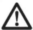
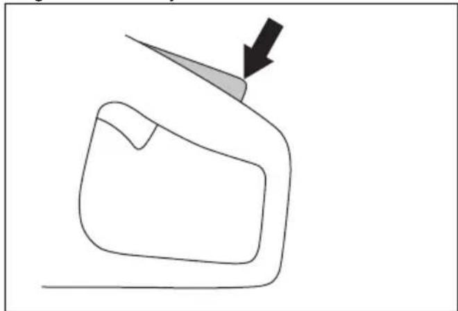
Power trigger lockout and ON/OFF valve for the water
The power trigger lockout prevents accidental operation of the power and adjust the water ON/OFF valve.
If you put your hand around the handle and push the power trigger lockout (A), it releases the power trigger (B) and opens the water valve.
If you release the handle, the power trigger and the power trigger lockout move back to their initial positions.
This function locks the power trigger and stops the product. The water valve goes back to closed position.
natural_image
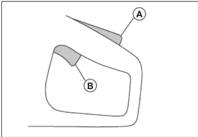
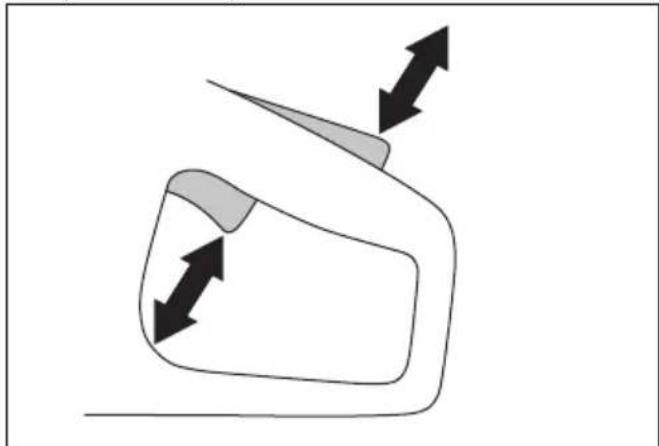
Simple line drawing of a vehicle or road with directional arrows indicating movement (no text or symbols)To do a check of the power trigger lockout
- Make sure that the power trigger is locked at the idle position when the power trigger lockout is released.
natural_image
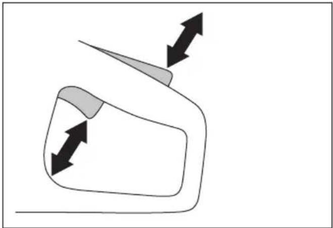
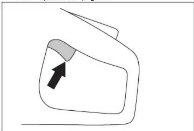
Simple line drawing of a car's front view with a directional arrow (no text or symbols)- Push the power trigger lockout and make sure that it goes back when you release it.
natural_image
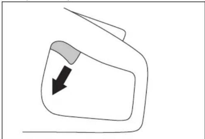
Simple line drawing of a mechanical part with an arrow pointing to a tip (no text or symbols)- Make sure that the power trigger and power trigger lockout move freely and that the return springs operate correctly.
natural_image
Simple line drawing of a vehicle or road with directional arrows indicating movement (no text or symbols)- Start the product and apply full speed. Refer to To start the product on page 23.
natural_image
Simple line drawing of a car's front and side view with an arrow indicating the direction (no text or symbols)- Release the power trigger and make sure that the cutting blade stops in less than 10 seconds and stays stationary.
natural_image
Simple line drawing of a car's side view with a black arrow indicating direction (no text or symbols)Blade guard and SmartGuard (Optional)
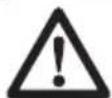
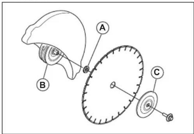
WARNING: Make sure that the blade guard and SmartGuard are correctly attached before you start the product. Do not use the product if the blade guard or SmartGuard is missing, defective or has cracks.
The blade guard (A) and SmartGuard (B) are installed above the cutting blade (C). They prevent injury if pieces of the blade or cut material are thrown in the direction of the operator.
The SmartGuard is spring loaded and must always move freely and retract to its initial position by spring force.
To examine the blade and the blade guard
WARNING: A damaged cutting blade can cause injury.
- Make sure that the cutting blade is attached correctly and does not show signs of damage.
- Make sure that the blade guard has no cracks or is damaged.
- Replace the blade guard if it is damaged.
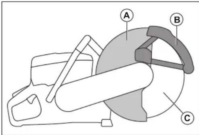
To do a check of the SmartGuard

WARNING: A damaged SmartGuard can cause injury.

CAUTION: The SmartGuard is a plastic guard and can become damaged by heat during intense dry cutting of metal with bonded abrasive blades. Do not do intense dry metal cutting and let the product become cool between the cuts. For intense metal cutting with SmartGuard, we recommend wet cutting together with vacuum brazed diamond blades, such as VARI-CUT FR3.
-
Make sure that the SmartGuard has no cracks or damage.
-
Make sure that the SmartGuard moves freely without much play and retracts by spring force.
natural_image
Diagram of a car steering wheel and steering wheel assembly with directional arrows indicating rotation (no text or labels)- Clean or replace the SmartGuard if it does not retract immediately when pushed in, or is damaged.
Start and overload protection
The product has an electronically controlled start and overload protection, Elgard ™ . The electronics stop the current immediately if the blade does not move freely.
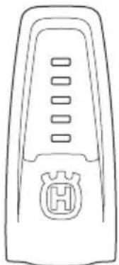
natural_image
Line drawing of a remote control device with a stylized 'H' logo on the side (no text or symbols)For explanation of the indication lamps, refer to the table in Lamp indicators in the product on page 24.
Vibration damping system
Your product is equipped with a vibration damping system that is designed to minimize vibration and make operation easier. The product's vibration damping system reduces the transfer of vibration between the motor unit/cutting equipment and the product's handle unit.
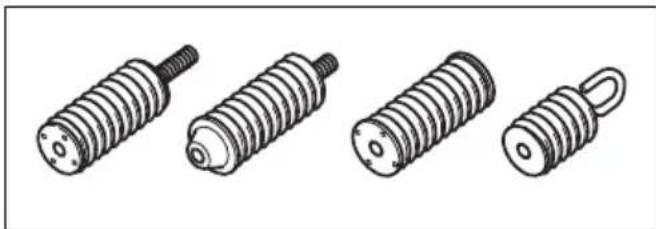
natural_image
Illustration of four different types of screwdrivers, shown in line drawings without any text or symbols.To do a check of the vibration damping system

WARNING: Make sure that the motor is off and that the power plug is disconnected.
- Make sure that there are no cracks or deformation on the vibration damping units. Replace the vibration damping units if they are damaged.
- Make sure that the vibration damping units are correctly attached to the motor unit and handle unit.
Safety instructions for maintenance
WARNING: Read the warning instructions that follow before you use the product.
• Make sure that the motor is off and that the power plug is disconnected.
- Use personal protective equipment. Refer to Personal protective equipment on page 8.
- If the maintenance is not done correctly and regularly, the risk of injury and damage to the product increases.
- Only do the maintenance as given in this operator's manual. Let an approved service center do all other servicing.
- Let an approved HUSQVARNA service agent do servicing on the product regularly.
- Replace damaged, worn or broken parts.
• Always use original accessories.
Assembly
Cutting blades

WARNING: Always use protective gloves when you assemble the product.
WARNING: A cutting blade can break and cause injury to the operator.

WARNING: Examine the cutting blade for cracks, lost segments distortion or unbalance prior to use and immediately after striking an unintended object. Do not use a damaged cutting blade. After inspecting and installing the cutting blade, position yourself and bystanders away from the plane of the rotating cutting blade and run the power tool at maximum no load speed for one minute.
WARNING: The cutting blade manufacturer gives warnings and recommendations for the operation and correct maintenance of the cutting blade. Those warnings are supplied with the cutting blade. Read and obey the instructions that are supplied with the cutting blade.
Diamond blades
WARNING: Diamond blades become very hot when used. A diamond blade that is too hot gives bad performance, blade damage and is a safety risk.
WARNING: Do not use diamond blades to cut plastic material. The hot diamond blade can melt the plastic, which can cause a kickback.
- Diamond blades have a steel core with segments that are made of industrial diamonds.
- Diamond blades are used for masonry, reinforced concrete and stone.
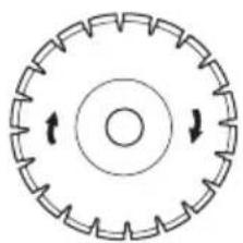
• Make sure that the diamond blade rotates in the direction of the arrows shown on the diamond blade.
natural_image
Circular mechanical gear or wheel diagram with directional arrows indicating rotational motion (no text or symbols)• Always use a sharp diamond blade.
- Diamond blades can become blunt if you use an incorrect feeding pressure or when you cut materials such as hard reinforced concrete. If you use a blunt diamond blade it becomes too hot, which can cause the diamond segments to come loose.
Cutting blades for handheld high speed power cutters
WARNING: Only use diamond blades. Do not use blades with serrations such as circular wood cutting blades or blades with carbide tips. The risk of kickback is increased and carbide tips can come off and
be thrown at high speed. This can result in injury or death.
WARNING: Incorrect use can cause the blade to become too hot. A blade that is too hot can cause malfunction, which can cause damage and injury.

WARNING: Do not use a cutting blade with a lower maximum speed than that of the power cutter. Only use cutting blades that are in compliance with national or regional standards.
Note: Only cut materials approved in the instruction supplied with the blade.
Check that the blade is approved for the same or higher speed written on the type plate of the power cutter.
Cutting blade vibration

CAUTION: If you use the product with too much force, the cutting blade can become too hot, bend and cause vibrations. Use the product with less force. If the vibrations continue, replace the cutting blade.
To sharpen the cutting blade
Note: For the best cutting results, use a sharp cutting blade.
- To sharpen the cutting blade, cut into soft material, such as sandstone or brick.
Diamond blades for wet cutting

WARNING: Always use a blade flange dimension that is specified for the current blade dimension. Do not use blade flanges that are damaged.
During the operation, the friction causes the diamond blade to become very hot. If the diamond blade becomes too hot, it will decrease the blade tension or make the core crack.
Let the diamond blade become cool before you touch it.
- Diamond blades for wet cutting must be used with water to keep the diamond blade core and segments cool during cutting. Diamond blades for wet cutting can not be used dry.
- If you use diamond blades for wet cutting without water, the diamond blade can become too hot. This gives bad performance, blade damage and is a safety risk.
Diamond blades for dry cutting
- For diamond blades for dry cutting it is necessary to have a sufficient airflow around the cutting blade to decrease the temperature. Because of this, diamond blades for dry cutting are recommended only for intermittent operation. After some seconds of operation, it is necessary to let the diamond blade rotate freely, away from the cut. This lets the airflow around the blade decrease the temperature of the diamond blade.
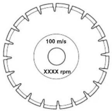
Diamond blade - requirements

WARNING: Make sure the diamond segment (T1) is wider than the blade (T2). This is to prevent pinching in the cutting slot and a kickback.
WARNING: Do not use diamond blades with positive rake angles.
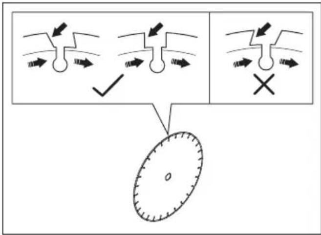

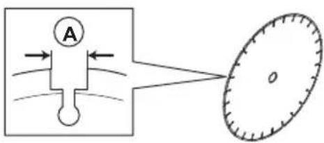
WARNING: Do not use diamond blades with greater gap between segments than max 10 mm (A).

WARNING: Do not use diamond blades with greater blade thickness than recommended maximum, refer to Recommended cutting blade dimensions on page 29.

WARNING: Some cutting situations and worn blades may cause increased wear on the side of the segments. Replace the blade before it is worn out.
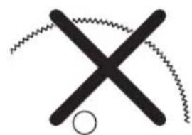
Toothed blades
WARNING: Never use toothed blades such as wood cutting blades, circular toothed blades, carbide tipped blades, etc. The risk of kickback is significantly increased and tips can be torn off and thrown at high speed. Carelessness can result in serious personal injury or even death.
WARNING: Government regulation requires a different type of guarding for carbide tipped blades not available on power cutters – a 360 degree guard. Power Cutters (this saw) use diamond blades and have a different guarding system which does not provide protection against the dangers presented by wood cutting blades.
natural_image
Simple black cross symbol with zigzag lines above and a small circle below (no text or symbols)Use of this power cutter with a carbide tipped blade is a violation of work safety regulations.
Due to the hazardous nature and exigent circumstances involved with fire fighting and rescue operations conducted by the various highly trained public safety forces, safety professionals (fire departments), Husqvarna is aware that they may use this power cutter with carbide tipped blades in certain emergency situations due to the ability of carbide tipped blades to cut many different types of obstructions and materials in combination without having to take time to switch blades or machines. When using this power cutter be aware at all times that carbide tipped blades are more kickback prone than diamond blades if not used properly. Carbide tipped blades can also throw pieces of material away from the blade.
For these reasons, a power cutter equipped with a carbide tipped blade should never be used except by highly trained public safety professionals who are aware of the risks associated with its use and then only in those exigent circumstances when other tools are deemed inefficient and ineffective for fire or rescue operations. A power cutter equipped with a carbide tipped blade should never be used to cut wood in non-rescue operations.
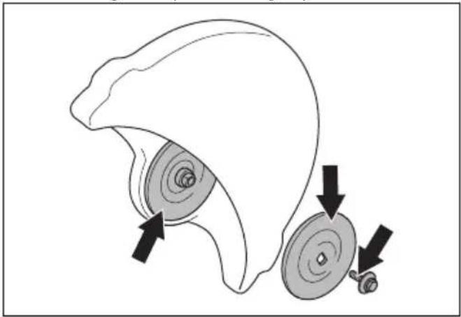
To examine the spindle shaft and the flange washers

CAUTION: Use only HUSQVARNA flange washers with a minimum diameter of 105 mm/4.1 in.

WARNING: Do not use defective, worn or dirty flange washers. Use only flange washers of the same dimension. Incorrect flange washers can cause the cutting blade to become damaged or come loose.
Examine the spindle shaft and the flange washers when you replace the cutting blade.
- Make sure that the threads on the spindle shaft are not damaged. Replace damaged parts.
natural_image
Diagram of a mechanical component with two circular parts and directional arrows indicating motion (no text or symbols)- Make sure that the areas of contact on the cutting blade and the flange washers are not damaged. Replace damaged parts.
- Make sure that the flange washers are clean and of the correct dimension.
- Make sure that the flange washers move freely on the spindle shaft.
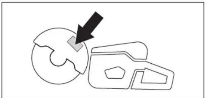
To do a check of the arbor bushing
The arbor bushings are used to attach the product to the center hole of the cutting blade. The product is supplied with one of these two types of arbor bushings:
- An arbor bushing that can be turned to the other side and be applicable for 20 mm/0.79 in. or 25.4 mm/1 in. center holes.
• A 25.4 mm/1 in. arbor bushing. - A decal on the blade guard shows installed arbor bushing and specification for applicable cutting blades.
natural_image
Diagram showing a gear mechanism with a black arrow pointing to a circular component (no text or symbols)- Make sure that the dimension of the center hole of the cutting blade agrees with the installed arbor bushing. The diameter of the center hole is printed on the cutting blade.
- Use only HUSQVARNA arbor bushings.
To examine the direction of rotation of the cutting blade
- Find the arrows on the rear belt guard that show the direction of rotation of the spindle shaft.
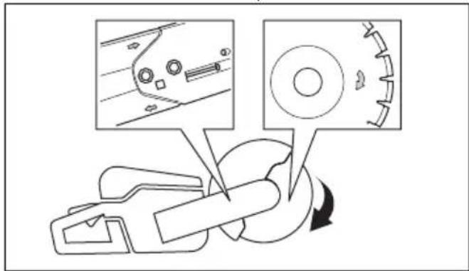
- Find the arrow on the cutting blade that shows the direction of rotation of the cutting blade.
- Make sure that the direction arrows of the cutting blade and the spindle shaft have the same direction.
To install the cutting blade
WARNING: Make sure that the engine is off and that the stop switch is in the STOP position.
WARNING: Always use protective gloves when you assemble the product.
- Examine the flange washers and the spindle shaft. Refer to To examine the spindle shaft and the flange washers on page 14.
- Push back and hold the SmartGuard in the retracted position.
natural_image
Diagram showing a car interior with steering wheel and directional arrows indicating motion (no text or symbols)Note: This step only applies to K 7000 SmartGuard.
- Put the cutting blade on the arbor bushing (A) between the inner flange washer (B) and the flange washer (C). Turn the flange washer until it holds on to the shaft.
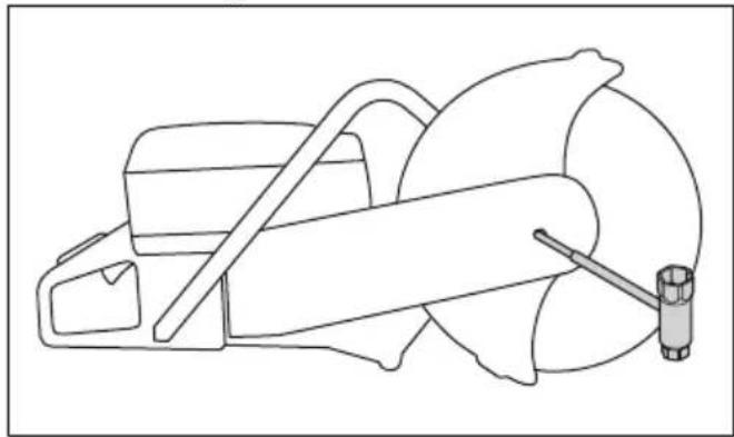
- Put a tool into the hole in the front belt guard and turn the cutting blade until the shaft is locked.
natural_image
Line drawing of a mechanical device with a tool and base (no text or symbols)- Tighten the cutting blade bolt to 25 Nm/18.5 ft-lb.
natural_image
Technical line drawing of a mechanical tool interacting with a saw (no text or symbols present)To reverse the cutting head
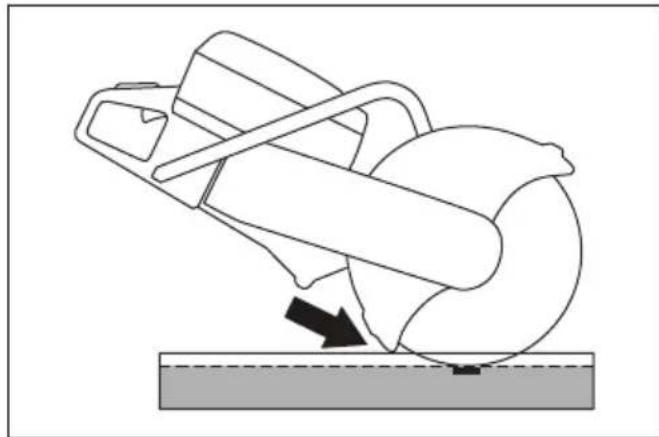
WARNING: Only cut with the cutting head reversed if a standard procedure is not possible.
The product has a reversible cutting head that lets you cut near a wall or at ground level. Only cut with the cutting head reversed if a standard procedure is not possible. If a kickback occurs, it is more difficult to control the product if the cutting head is reversed. The distance between the cutting blade and the center of the product is longer, which means that the handle and the cutting blade do not align. This has a negative effect on the balance in the product and it is more difficult to hold
the product if the cutting blade is pinched or stalled in the kickback zone. Refer to Kickback zone on page 17.
WARNING: Make sure that the motor is off and that the power plug is disconnected.

WARNING: Always use protective gloves when you assemble the product.
- Remove the cutting blade, refer to To install the cutting blade on page 15.
- Loosen the 2 bolts and the adjuster to release the belt tension.
natural_image
Technical line drawing of a mechanical device with arrows indicating assembly or component (no text or symbols)- Remove the bolts and release the belt guard.
natural_image
Technical line drawing of a mechanical assembly with no visible text or symbols-
Disconnect the water hose nipple, the water hose and the handle from the blade guard. Remove the stop.
-
Remove the belt from the pulley.
natural_image
Technical line drawing of a mechanical assembly with no visible text or symbols- Turn the bearing housing to opposite direction and assemble the stop.
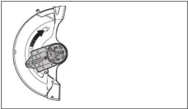
natural_image
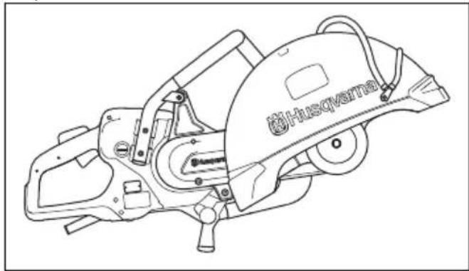
Technical line drawing of a mechanical component with no visible text or symbols- Attach the cutting head to the other side of the product.
natural_image
Technical line drawing of a mechanical device with 'Husqerna' branding (no text or symbols on the diagram itself)-
Tighten the drive belt. Refer to To adjust the tension of the drive belt on page 25.
-
Connect the water hose nipple and the water hose on the top of the blade guard.
Operation
Introduction
WARNING: Read and understand the safety chapter before you use the product.
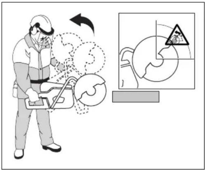
Kickback

WARNING: Kickbacks are sudden and can be very violent. The power cutter can be thrown up and back towards the user in a rotating motion causing serious or even fatal injury. It is vital to understand what causes kickback and how to avoid it before using the product.
Kickback is the sudden upward motion that can occur if the blade is pinched or stalled in the kickback zone. Most kickbacks are small and pose little danger.
However a kickback can also be very violent and throw the power cutter up and back towards the user in a rotating motion causing serious or even fatal injury.
Reactive force
A reactive force is always present when cutting. The force pulls the product in the opposite direction to the blade rotation. Most of the time this force is insignificant. If the blade is pinched or stalled, the reactive force will
be strong and you might not be able to control the power cutter.
natural_image
Diagram showing a mechanical component interacting with a globe and directional arrow (no text or symbols)Never move the product when the cutting equipment is rotating. Gyroscopic forces can obstruct the intended movement
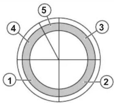
Kickback zone
Never use the kickback zone of the blade for cutting. If the blade is pinched or stalled in the kickback zone, the reactive force will push the power cutter up and back towards the user in a rotating motion causing serious or even fatal injury.
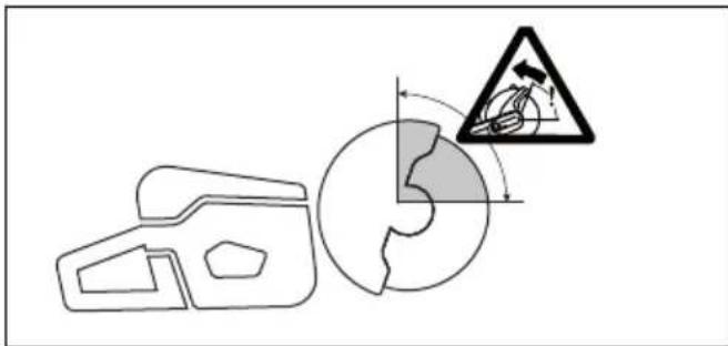
Rotational kickback
A rotational kickback occurs when the cutting blade does not move freely in the kickback zone.
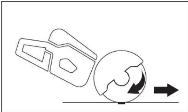
Climbing kickback
If the kickback zone is used for cutting, the reactive force drives the blade to climb up in the cut. Do not use the kickback zone. Use the lower quadrant of the blade to avoid climbing kickback.
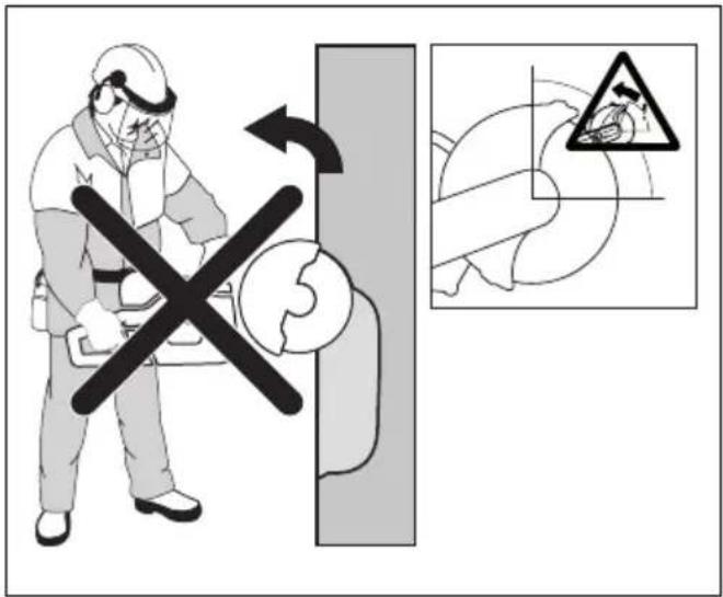
Pinching kickback
Pinching is when the cut closes and pinches the blade. If the blade is pinched or stalled the reactive force will be
strong and you might not be able to control the power cutter.
natural_image
Diagram of a medical procedure with a cross symbol crossed over a device on a table (no text or labels)If the blade is pinched or stalled in the kickback zone, the reactive force will push the power cutter up and back towards the user in a rotating motion causing serious or even fatal injury. Be alert for potential movement of the work piece. If the work piece is not properly supported and shifts as you cut, it might pinch the blade and cause a kick back.
Pipe cutting
Special care should be taken when cutting in pipes. If the pipe is not properly supported and the cut kept open throughout the cutting, the blade might be pinched. Be especially alert when cutting a pipe with a belled end or a pipe in a trench that, if not properly supported, may sag and pinch the blade.
If the pipe is allowed to sag and close the cut, the blade will be pinched in the kick back zone and a severe kick back might develop. If the pipe is properly supported, the end of the pipe will move downward, the cut will open and no pinching will occur.
Secure the pipe so it does not move or roll during cutting. Make sure that the cut opens to avoid pinching the blade.
To cut in smaller pipes
WARNING: If the blade is pinched in the kickback zone, it will cause a severe kickback.
If the pipe is smaller than the maximum cutting depth of the product, the cutting operation can be done in 1 step from top to bottom.
- Cut the pipe from top to bottom.
natural_image
Simple line drawing of a car outline and a circular diagram with a downward arrow (no text or symbols)To cut in larger pipes
WARNING: If the blade is pinched in the kickback zone it will cause a severe kickback.
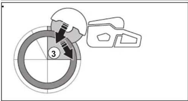
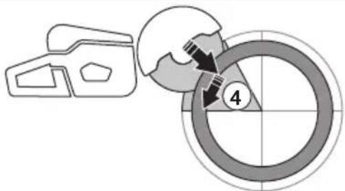
If the pipe is larger than the maximum cutting depth of the product, and can not be rolled, the cutting operation needs to be divided in 5 steps.
- Divide the pipe into 5 sections. Do a mark of those sections and of a cutting line. Cut a shallow guide groove around the pipe.
- Cut those sections in 5 steps with the cutting directions shown by the arrows in each step.
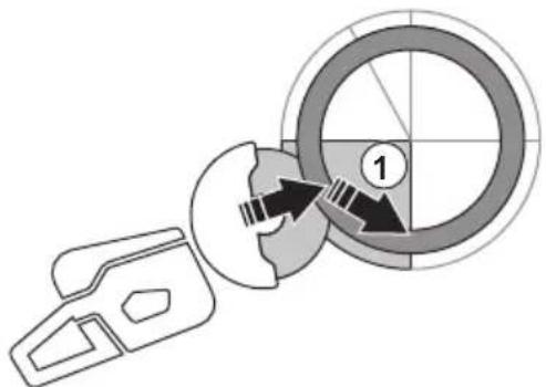
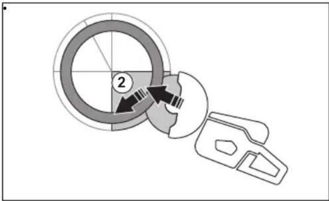

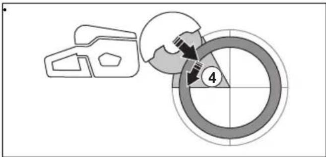
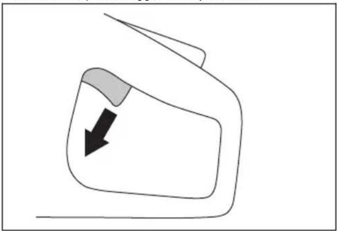
- Make the final separating cut from the top of the pipe pulling backwards, without involving the upper quadrant of the blade. Adjust the blade guard to full forward position for maximum protection.
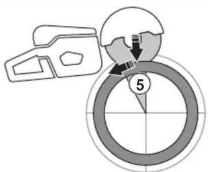
WARNING: If the pipe is properly supported, it should not pinch the blade when separated in section 5. However be alert if the blade is pinched during the final separation. If the blade is pinched in the lower section, the product may pull forward away from the operator, rather then resulting in a rotating kickback.
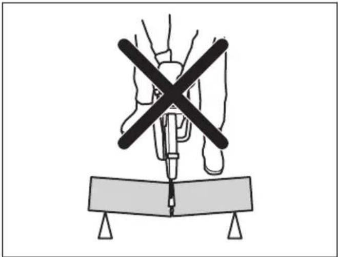
To prevent a kickback

WARNING: Avoid situations where there is a risk of kickback. Take care when using your power cutter and make sure that the blade is never pinched in the kickback zone.

WARNING: Be careful when you put the blade in an existing cut.

WARNING: Make sure that the work piece cannot move during a cutting operation.

WARNING: Only you and proper working technique can eliminate kickback and its dangers.
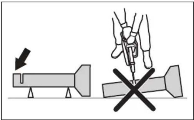
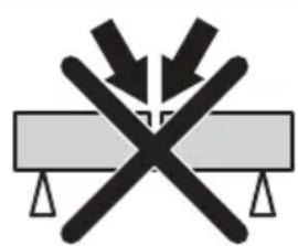
- Always support the work of piece so that the cut can keep open when cutting through. When the cut is open there is no kickback. If the cut is closed and pinches the blade, there is a risk of kickback.
natural_image
Symbolic illustration of crossed-out black-and-white lines crossing over a gray rectangular block, with no text or symbols present.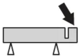
natural_image
Simple diagram of a beam with supports and a downward arrow indicating force or direction (no text or symbols)To do before you start the product
- Read the operator's manual carefully and make sure that you understand the instructions.
- Do the daily maintenance. Refer to Maintenance schedule on page 25.
- Make sure that the power pack is connected to a grounded power outlet.
- Make sure that the mains voltage agrees with the specification on the rating plate on the product.
- Make sure that only approved persons are in the work area.
- Make sure that you are in a safe and stable position during operation.
- Always use a power pack with RCD. Refer to the operator's manual for the power pack.
- Make sure that the water connector is connected with a water supply. Refer to To connect the water supply on page 22.
To decrease dust during operation
The product has a wet cutting kit to decrease harmful dust in the air during operation. The wet cutting kit has low water consumption.
- When possible, use wet cutting blades with water cooling. Refer to Diamond blades for wet cutting on page 13.
- Adjust the water flow with the valve. The correct flow is different for different types of tasks.
- Make sure that the water pressure is correct. Refer to Technical data on page 28. If the water hose comes off at the supply source, the supplied water pressure can be too high.
Basic working techniques

WARNING: Do not pull the product to one side. This can prevent the free movement of the cutting blade. The cutting blade can break and cause injury to the operator or bystanders.

WARNING: Do not grind with the side of the cutting blade. The cutting blade can break and cause injury to the operator or bystanders. Only use the cutting edge.
WARNING: Make sure that the cutting blade is installed correctly and does not show signs of damage.
WARNING: Before cutting in an existing cut made by a different blade, make a sure that the slot is not thinner than your blade as that can result in binding in the cutting slot and a kickback.

WARNING: Cutting metal generates sparks that can cause fire. Do not use the product near flammable material or gases.
- The product is made to cut with diamond blades made for high speed handheld product. The product must not be used with other types of blade, or for other types of operation.
- Do a check that the correct cutting blade is used for the material to be cut. Refer to Cutting blades on page 12 for instructions.
- Do not cut asbestos materials.
- Keep a safe distance from the cutting blade when the motor is on. Do not try to stop a rotating blade with a part of your body. To touch a rotating blade, although the motor is off, can result in serious injury or death.
- Make sure that only approved persons are in the work area.
- The cutting blade continues to rotate for a while after the power trigger is released. Make sure that the cutting blade has stopped before the product is moved or put down. If it is necessary to stop the
cutting blade quickly, let the cutting blade lightly touch a hard surface.
- Do not move the product with the motor on.
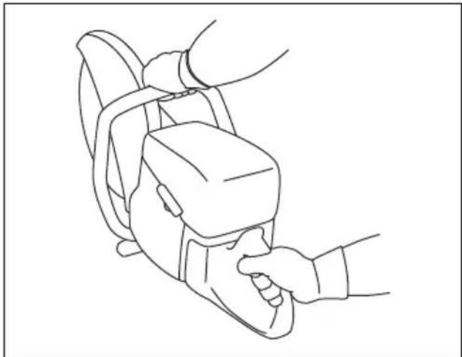
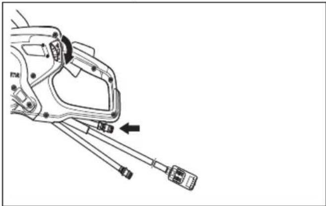
- Hold the product with 2 hands. Hold the product tightly with thumbs and fingers fully around the plastic handles with insulation. The right hand must be on the rear handle and the left hand on the front handle. All operators must use this hold. Do not operate a power cutter with only 1 hand.
natural_image
Line drawing of a person using a handheld device to interact with another person (no text or symbols present)• Make sure that you stay in a safe position and that the cutting blade can move freely.
- Stand parallel to the cutting blade. Avoid standing straight behind. If a kickback occur, the saw will move in the plane of the cutting blade.
- Do not go away from the product with the motor on. Before you go away from the product, stop the motor and make sure that there is no risk of accidental start.
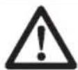
- Use the adjustment handle of the blade guard to adjust the rear section of the guard flush with the work piece. Spatter and sparks from the cut material are then collected up by the guard and led away from the operator. The guards for the cutting
equipment must always be installed when the product is on.
natural_image
Diagram of a mechanical device with a rotating arm and base, showing motion direction (no text or symbols)- Do not use the kickback zone of the blade for cutting. Refer to Kickback zone on page 17 for instructions.
- Do not operate the product before the work area is clear and your feet and body are in a stable position.
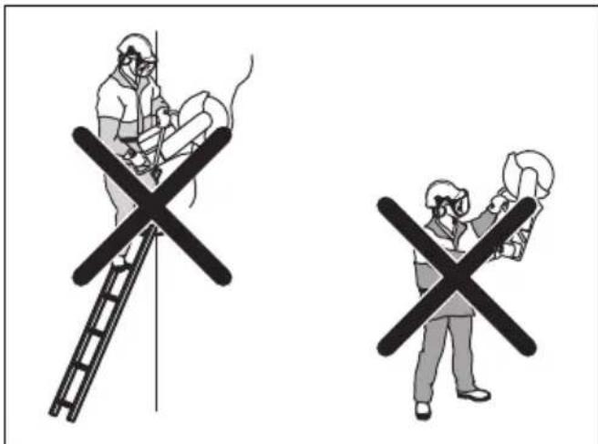
- Do not cut above shoulder height.
- Do not cut from a ladder. Use a platform or scaffold if the cut is above shoulder height. Do not overreach.
- Stay at a comfortable distance from the work piece.
- Make sure that the cutting blade can move freely when the motor is started.
- Apply the cutting blade carefully with high rotating speed (full power). Keep full speed until cutting is complete.
- Let the product do the work. Do not push the cutting blade.
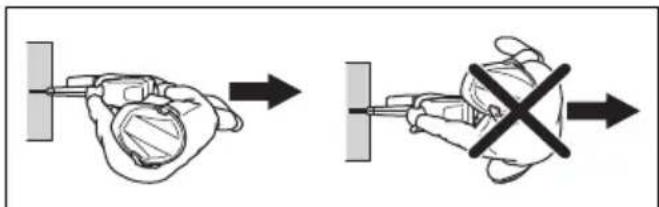
- Feed the product down in line with the blade. Pressure from the side can cause damage to the blade and is very dangerous.
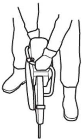
natural_image
Line drawing of a person using a handheld device to lift a foot (no text or symbols)- Move the blade slowly forward and rearward to get a small contact area between the blade and the material to be cut. This decreases the temperature of the blade and is an effective way to cut.
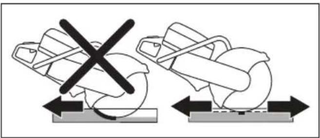
natural_image
Diagram showing two mechanical components with a crossed X-axis, no text or symbols presentBasic working techniques with K 7000 SmartGuard
WARNING: The SmartGuard function is disengaged if the SmartGuard is manually retracted. Only retract the SmartGuard manually if you must and there are no risks of kickback.
SmartGuard gives more coverage of the blade. This decreases the risk that you touch the blade if a kickback occurs.
- You can retract the SmartGuard manually with the SmartGuard handle.
- Hold the SmartGuard handle with a left hand finger while the remaining fingers hold the front handle at the same time.
natural_image
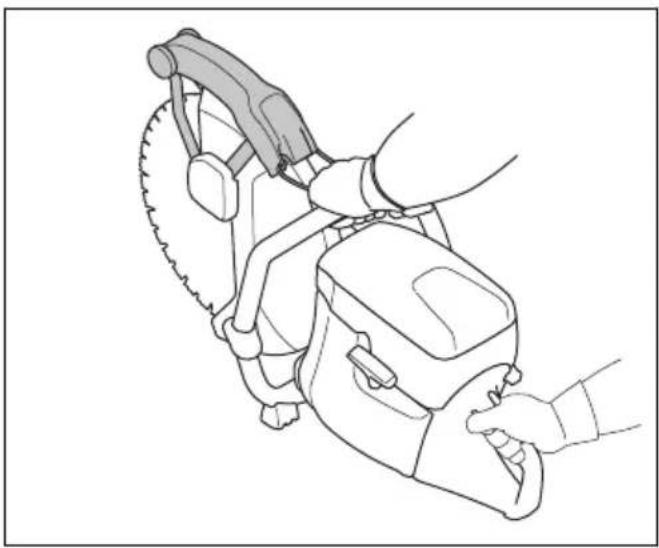
Line drawing of a person using a chain saw to cut a saw (no text or symbols present)To do a check of the RCD 3 phase
- Start the product, refer to page 23.
To start the product on - Look into the inspection holes and push the RCD test button.
- Make sure that the RCD moves and that it disconnects the product from the power supply.
- Turn the RCD reset knob to reset the RCD.
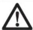
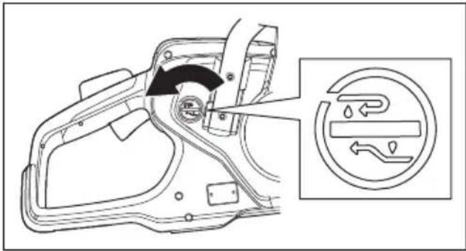
To connect the water supply
CAUTION: Always use water when you operate the product. The temperature of the product is decreased by water also during dry cutting.
CAUTION: Use correct water pressure to keep the diamond blade core and segments cool when you cut. Diamond blades for wet cutting cannot be used dry.
- Connect the water hose to the water supply. Refer to Technical data on page 28 for the lowest permitted water flow.
natural_image
Line drawing of a hand holding a connector with a threaded cable inserted (no text or symbols)Note: The hose nipple of the product has a filter.
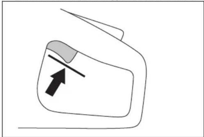
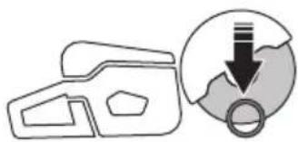
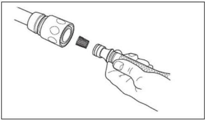
- Push the power trigger lockout to open the water valve.
natural_image
Simple line drawing of a mechanical part with an arrow pointing to a tip (no text or symbols)- Adjust the water flow with your thumb during the operation.
natural_image
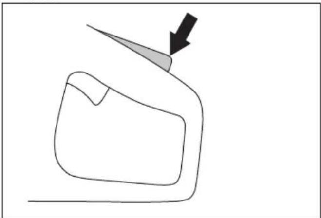
Technical line drawing of a mechanical component with no visible text or symbolsTo dry cut
CAUTION: Diamond blades for dry cutting are recommended only for intermittent operation.

CAUTION: Always use sufficient airflow around the cutting blade to decrease the temperature.
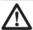
- Turn the button 180irc to adjust the direction of the water.
- Push the knob to stop the flow of water.
natural_image
Technical line drawing of a mechanical linkage component with connectors and a directional arrow (no text or symbols)The water goes through the return hose.
To start the product
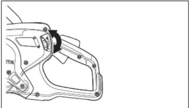
- Hold the rear handle with your right hand.
natural_image
Line drawing of a mechanical device with hands operating it, no text or symbols present- Push the power trigger lockout and hold in the power trigger.
- Let the product operate with no load for 30 seconds.
To stop the product

WARNING: The cutting blade continues to rotate for a while after the motor stops. Make sure that the cutting blade can rotate freely until it fully stops. If it is necessary to stop the cutting blade quickly, let the cutting blade lightly touch a hard surface. Risk of serious injury.
There are 2 procedures to stop the motor.
- Release the power trigger to stop the motor.
- Push the machine stop button on the power pack. Refer to the operator's manual for the power pack.
natural_image
Simple line drawing of a car's side view with a black arrow indicating direction (no text or symbols)Lamp indicators in the product
| Indication Cause Step | ||
| 1 green lamp flashes. | The product is connected to a power pack and is prepared for operation.The power output is less than 70% of the maximum available output in operation. | N/A |
| 2 green lamps flash. | The power output is 70-90 % of the maximum available output in operation. | N/A |
| 3 green lamps flash. | The cutting speed is at its best performance.The power output is 90 % of the maximum available output in operation. | N/A |
| 3 green and 1 yellow lamps flash. | The power output drops. Decrease the load. | |
| 3 green, 1 yellow and 1 red lamps flash. | The product is too hot. Decrease the load or increase | the water flow or airflow to decrease the temperature. |
| All the status indication lamps flash. | The product is too hot. Decrease the load or increase | the water flow or airflow to decrease the temperature. |
| The power is decreased. Increase the water flow or airflow to decrease the temperature. | ||
| The system is in automatic shutdown. Put the power pack in a location with lower temperature. | ||
| Replace the air filter. |
Maintenance
Introduction

WARNING: Read and understand the safety chapter before you do maintenance on the product.
For all servicing and repair work on the product, special training is necessary. We guarantee that professional repairs and servicing is available. If your dealer is not a
service agent, speak to them for information about the nearest service agent.
For spare parts, speak to your HUSQVARNA dealer or service agent.
Maintenance schedule
The maintenance schedule shows the necessary maintenance of the product. The intervals are calculated on daily use of the product.
| Daily Weekly or every 40 hours Monthly | |||
| Clean External cleaning | |||
| Function inspection | General inspection Vibration damping system* | ||
| Water delivery system Drive belt | |||
| Throttle lockout* | |||
| Blade guard and SmartGuard* | |||
| Cutting blade** Drive wheel | |||
| * Refer to Safety devices on the product on page 9. ** Refer to To install the cutting blade on page 15. | |||
To clean externally
WARNING: Do not use a high-pressure washer to clean the product.
- Flush the product externally with clean water after each day of operation. If it is necessary, use a brush.
To do a general inspection
• Make sure that the nuts and screws on the product are tightened.
- Make sure that the cables on the product are not in a position where they can become damaged.
- Examine the electrical parts for damage. Do not operate a product that has damaged electrical parts.
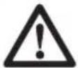
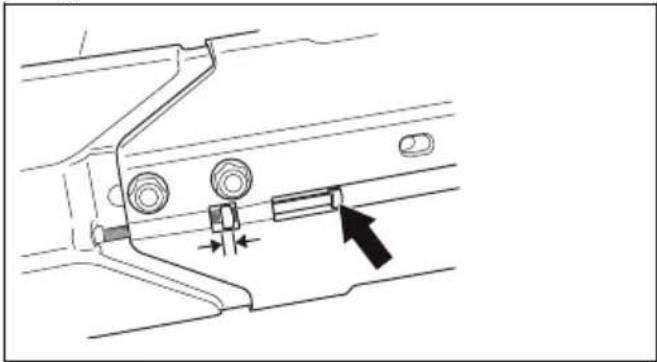
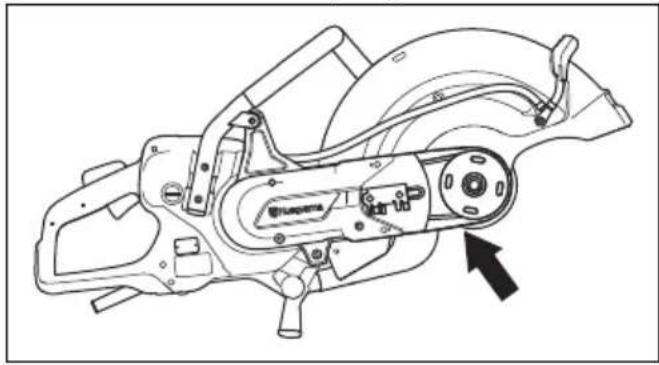
To adjust the tension of the drive belt
The tension of the drive belt is correct when the adjustment nut is opposite the mark on the drive belt cover.
natural_image
Technical diagram of a mechanical component with a black arrow indicating a specific feature (no text or symbols present)Tighten a new drive belt after 1 hour of operation.
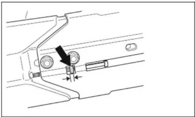
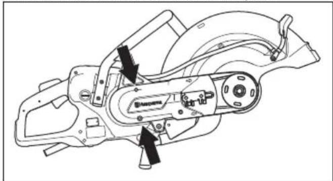
- Loosen the 2 bolts that hold the cutting head to the product.
natural_image
Technical line drawing of a mechanical device with two black arrows pointing to specific components (no text or symbols present)- Turn the adjuster screws until the adjustment nut is opposite the mark on the drive belt cover.
natural_image
Technical diagram of a mechanical component with no visible text or symbols- Use a combination wrench and tighten the 2 bolts that hold the cutting head to the product.
To replace the drive belt
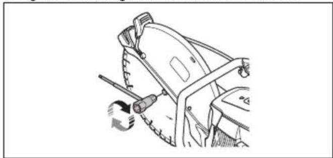
- Turn the bolt for the cutting blade counterclockwise with a wrench to remove the cutting blade.
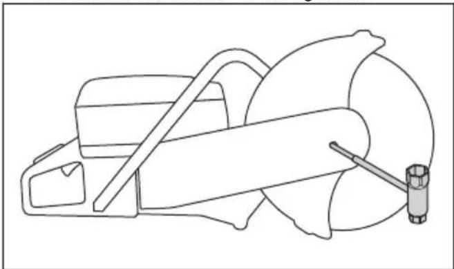
natural_image
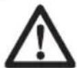
Line drawing of a mechanical device with a handle and lever (no text or symbols)- Loosen the 2 bolts and then the adjuster screw to release the belt tension.
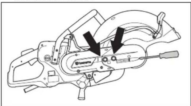
- Remove the 2 bolts and remove the belt guard.
natural_image
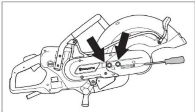
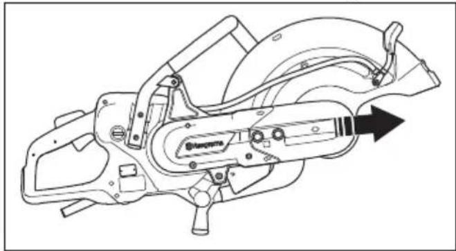
Technical line drawing of a mechanical assembly with no visible text or symbols- Remove the belt from the pulley.
natural_image
Technical line drawing of a mechanical assembly with no visible text or symbolsNote: The cutting head can be removed from the product.
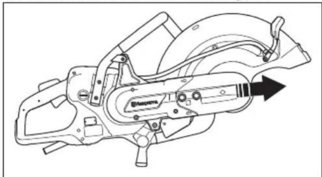
- Loosen the 2 screws that hold the belt guard.
natural_image
Technical line drawing of a mechanical assembly with no visible text or symbols-
Remove the rear belt guard.
-
Replace the drive belt.
-
Assemble in opposite sequence. To install the cutting blade, refer to To install the cutting blade on page 15.
Transportation, storage and disposal
Transportation and storage
- Secure the product during transportation to prevent damage and accidents.
- Remove the cutting blade before transportation or storage of the product.
- Keep the product in a locked area to prevent access for children or persons that are not approved.
- Keep the cutting blades in dry, frost free conditions.
- Disconnect the power source from the product.
- Examine all new and used blades for transport and storage damage before assembly.
Disposal
Symbols on the product or the packaging of the product indicate that this product cannot be handled as domestic waste. It must be submitted to an appropriate recycling station for the recovery of electrical and electronic equipment.
By ensuring that this product is taken care of correctly, you can help to counteract the potential negative impact on the environment and people that can otherwise result through the incorrect waste management of this product. For more detailed information about recycling this product, contact your municipality, your domestic waste service or the shop from where you purchased the product.
natural_image
Symbol of a trash bin crossed out by two diagonal lines, no text or numbers presentTechnical data
Technical data
| Motor | |
| Electric motor HF High Frequency | |
| 3-phase operation, Motor output - max kW 5.5 | |
| 1-phase operation, Motor output - max kW 3 | |
| 1-phase, V 120-240 | |
| Weight | |
| K 7000 without cutting blade and cable package, lbs/kg 2 | .6/9.8 |
| K 7000 SmartGuard without cutting blade and cable package, lbs/kg | 23.8/10.8 |
| K 7000 cable package, lbs/kg 4.2/1.9 | |
| Spindle, output shaft | |
| Max. spindle speed, rpm 4300 | |
| Max. peripheral speed, ft/min or m/s 18000 or 90 | |
| Water cooling | |
| Water cooling of blade Yes | |
| Recommended water pressure, PSI/bar 7-116 / 0.5-8 | |
| Min. recommended water flow, l/min, qt/min 0.5 at water temperature 15°C, 0.5 at water temperature 59F | |
| Connecting nipple Type Gardena | |
| Noise emission1 | |
| Sound power level, measured dB(A) | 104 |
| Sound levels2 | |
| Sound pressure level at the operators ear, dB(A) | 93 |
| Equivalent vibration levels , ahveq3 | |
| Front handle, m/s2 | 1.8 |
| Rear handle, m/s2 | 1.6 |
| 1. Noise emissions in the environment measured as sound power (LWA) conforming to EN 60745-2-22.Reported data for noise power level has an uncertainty of 3 dB(A).2. Noise pressure level according to EN 60745-2-22. Reported data for noise pressure level has an uncertainty of 3 dB(A).3. Equivalent vibration level, according to EN 60745-2-22, is calculated as the time-weighted energy total for vibration levels. Reported data for vibration levels has an uncertainty of 1.5 m/s2. | |
Recommended cutting blade dimensions
| Max. cutting blade diameter, in./mm | Max. cutting depth in./mm | Blade speed rat-ing, rpm | Blade speed rat-ing, ft/min or m/s | Blade center hole diameter, in./mm | Max. blade thickness, in./mm |
| 16/400 6/155 4775 | 19600 or 100 0.79/20 or 1/25.4 0.2/5 |
Declaration of Conformity
EU Declaration of Conformity
We, Husqvarna AB, SE-561 82 Huskvarna, Sweden, tel: +46-36-146500, declare on our sole responsibility that the product:
| Description Portable cut-off machine | |
| Brand HUSQVARNA | |
| Type/Model K 7000, K 7000 SmartGuard | |
| Identification Serial numbers dating from 2021 and onwards |
complies fully with the following EU directives and regulations:
| Directive/Regulation Description | |
| 2006/42/EC "relating to machinery" | |
| 2014/30/EC "relating to electromagnetic compatibility" | |
| 2011/65/EU "relating to restriction of hazardous substances" |
EN ISO 12100:2010, EN 60745-1:2009, EN 60745-2-22:2011/A11:2013, EN 61000-3-2:2014, EN 61000-3-3:2013, EN 55014-1:2017, EN 55014-2:2015, EN IEC 63000:2018
Partille, 2021-04-29
Erik Silfverberg
R&D Director, Concrete Sawing & Drilling Equipment
Husqvarna AB, Construction Division
Responsible for technical documentation

UK Declaration of Conformity
We, Husqvarna AB, SE-561 82 Huskvarna, Sweden, tel:
+46-36-146500, declare on our sole responsibility that
the product:
| Description Portable cut-off machine | |
| Brand HUSQVARNA | |
| Type/Model K 7000, K 7000 SmartGuard | |
| Identification Serial numbers dating from 2021 and onwards |
complies fully with the following UK directives and
regulations:
| Regulation Description | |
| S.I. 2008/1597 The Supply of Machinery (Safety) Regulations 2008 | |
| S.I. 2016/1091 Electromagnetic Compatibility Regulations 2016 | |
| S.I. 2012/3032 The Restriction of the Use of Certain Hazardous Substances in Electrical and Electronic Equipment Regulations 2012 | |
EN ISO 12100:2010, EN 60745-1:2009, EN
60745-2-22:2011/A11:2013, EN 61000-3-2:2014, EN
61000-3-3:2013, EN 55014-1:2017, EN 55014-2:2015,
EN IEC 63000:2018
Partille, 2021-04-29

Erik Silfverberg
R&D Director, Concrete Sawing & Drilling Equipment
Husqvarna AB, Construction Division
Responsible for technical documentation

UK Importer:
Husqvarna UK Limited
Preston Road, Aycliffe
Business Park Newton
Aycliffe, County Durham
UK DL5 6UP
Inhalt
Einleitung.... 32
Sicherheit....35
Montage....43
Betrieb....49
Wartung....57
natural_image
Illustration of a person wearing full-body protective gear and a first aid kit (no text or symbols)natural_image
Simple line drawing of a vehicle or road with directional arrows indicating movement (no text or symbols)natural_image
Simple line drawing of a device with an arrow pointing to a section (no text or symbols)natural_image
Simple line drawing of a mechanical part with an arrow pointing to a tip (no text or symbols)natural_image
Simple line drawing of a vehicle or road with directional arrows indicating movement (no text or symbols)natural_image
Simple line drawing of a car's front and side view with an arrow indicating the direction (no text or symbols)natural_image
Simple line drawing of a vehicle or container with an arrow indicating direction (no text or symbols)natural_image
Diagram of a car steering wheel and dashboard with directional arrows indicating rotation (no text or symbols)natural_image
Line drawing of a remote control device with a stylized 'H' logo on the front panel (no text or symbols)natural_image
Illustration of four different types of threaded fasteners or connectors, shown in line drawings without any text or symbols.natural_image
Circular mechanical component with evenly spaced teeth and central bore, no text or symbols present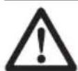

natural_image
Simple black cross symbol with a zigzag line above and a circle below, no text or symbols present.natural_image
Diagram of a mechanical component with two circular parts and directional arrows indicating motion (no text or symbols)natural_image
Diagram showing a gear mechanism with a black arrow pointing to a specific component (no text or symbols present)natural_image
Diagram of a mechanical device with rotating components and directional arrows (no text or symbols)natural_image
Line drawing of a mechanical device with a handle and lever (no text or symbols)natural_image
Technical line drawing of a mechanical tool or cutting machine (no text or symbols visible)natural_image
Technical line drawing of a mechanical device with no visible text or symbolsnatural_image
Technical line drawing of a mechanical assembly with no visible text or symbolsnatural_image
Technical line drawing of a mechanical assembly with no visible text or symbolsnatural_image
Technical line drawing of a mechanical component with curved and straight sides, no visible text or symbolsnatural_image
Technical line drawing of a mechanical device with 'Hasqerna' branding on the cover (no other text or symbols)natural_image
Diagram showing a mechanical device interacting with a circular component, with directional arrows indicating motion (no text or symbols)Blockierung
natural_image
Diagram of a medical procedure with a surgical tool and X-shaped cross symbol above a table (no text or labels)natural_image
Simple line drawing of a device and a circular diagram with a downward arrow (no text or symbols)natural_image
Diagram showing a mechanical component interacting with a circular target, with arrows indicating motion or force direction (no text or symbols present)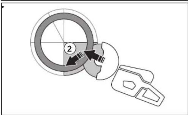
natural_image
Symbolic illustration of crossed black lines crossing a horizontal bar with triangular supports (no text or labels)
natural_image
Simple diagram of a beam with supports and a downward arrow indicating force or direction (no text or symbols)natural_image
Line drawing of a person using a handheld device to interact with another person (no text or symbols present)natural_image
Diagram of a mechanical device with a rotating shaft and base, showing motion direction (no text or symbols)natural_image
Line drawing of a person using a bicycle to lift a foot (no text or symbols)natural_image
Diagram showing two mechanical components with a cross symbol, no text or labels presentnatural_image
Line drawing of a person using a cutting tool on a machine (no text or symbols)natural_image
Line drawing of a hand holding a connector with a cable, showing the cable being inserted (no text or symbols present)natural_image
Simple line drawing of a mechanical part with an arrow indicating direction (no text or symbols)natural_image
Technical line drawing of a mechanical component with no visible text or symbolsnatural_image
Technical line drawing of a mechanical assembly with connectors and a directional arrow (no text or symbols)natural_image
Line drawing of a mechanical tool with hands operating it, no text or symbols presentnatural_image
Simple line drawing of a vehicle or container with an arrow indicating direction (no text or symbols)natural_image
Technical line drawing of a mechanical component with no visible text or symbolsnatural_image
Technical line drawing of a mechanical assembly with two black arrows pointing to specific components (no text or symbols present)natural_image
Technical diagram of a mechanical component with arrows indicating movement or force (no text or symbols)natural_image
Line drawing of a mechanical device with a tool and base (no text or symbols)natural_image
Technical line drawing of a mechanical tool with arrows indicating assembly or component (no text or symbols present)natural_image
Technical line drawing of a mechanical assembly with no visible text or symbolsnatural_image
Technical line drawing of a mechanical assembly with no visible text or symbolsnatural_image
Technical line drawing of a mechanical assembly with no visible text or symbolsnatural_image
Symbol of a trash bin crossed with two diagonal lines, no text or labels presentTechnische Daten
Technische Daten
Husqvarna AB, Construction Division
natural_image
Illustration of a person wearing full-body protective gear and a first aid kit (no text or symbols)Précautions relatives aux vibrations

natural_image
Simple line drawing of a vehicle's side profile with arrows indicating direction (no text or symbols)natural_image
Simple line drawing of a vehicle's front view with a diagonal arrow indicating direction (no text or symbols)natural_image
Simple line drawing of a mechanical part with an arrow indicating direction (no text or symbols)natural_image
Simple line drawing of a vehicle or road with directional arrows indicating movement (no text or symbols)natural_image
Simple line drawing of a car's front view with a black arrow pointing to the side panel (no text or symbols)natural_image
Simple line drawing of a car door with a black arrow indicating left side (no text or symbols)natural_image
Diagram of a car steering wheel and dashboard with motion arrows indicating rotation (no text or symbols)natural_image
Line drawing of a remote control device with a stylized 'H' logo on the side (no text or symbols)natural_image
Illustration of four different types of screwdrivers, shown in line drawings without any text or symbols.natural_image
Circular mechanical gear diagram with evenly spaced teeth and central bore (no text or symbols)
natural_image
Simple black cross symbol with a wavy line above it and a circle below, no text or labels present.natural_image
Diagram of a medical device with two circular components and directional arrows indicating movement or force (no text or symbols)natural_image
Simple line drawing of a globe with a black arrow pointing to it, next to a stylized 3D object (no text or symbols)natural_image
Diagram of a mechanical device with rotating components and directional arrows (no text or symbols)natural_image
Line drawing of a mechanical device with a handle and base, no text or symbols presentnatural_image
Technical line drawing of a mechanical device with a tool and base (no text or symbols)natural_image
Technical line drawing of a mechanical tool or device with no visible text or symbolsnatural_image
Technical line drawing of a mechanical assembly with no visible text or symbolsnatural_image
Technical line drawing of a mechanical assembly with no visible text or symbolsnatural_image
Technical line drawing of a mechanical component with no visible text or symbolsnatural_image
Technical line drawing of a mechanical device with no visible text or symbolsnatural_image
Diagram showing a mechanical device interacting with a circular component, with directional arrows indicating motion (no text or symbols)Rebond rotationnel
Rebond de grimpée
Rebond de pincement
natural_image
Diagram of a medical procedure with a surgical tool and X-shaped cross symbol (no text or labels)natural_image
Simple line drawing of a helmet and gear with a download icon (no text or symbols)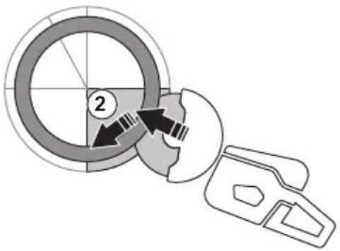
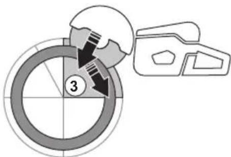
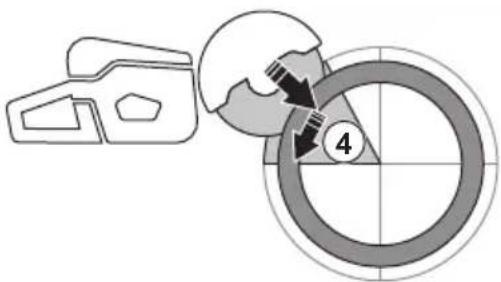
natural_image
Symbolic illustration of crossed-out black arrows over a gray rectangular block, with no text or labels present.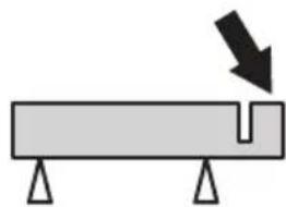
natural_image
Simple diagram of a beam with supports and a downward arrow indicating force or direction (no text or symbols)natural_image
Line drawing of a hand holding a small object, possibly a device or device, with no visible text or symbols.natural_image
Diagram of a mechanical device with a rotating shaft and base, showing motion direction (no text or symbols)natural_image
Line drawing of a person using a handheld device to lift or lift an object, wearing boots (no text or symbols)natural_image
Diagram showing two mechanical components with a cross mark, no text or symbols presentnatural_image
Line drawing of a person using a cutting tool to cut a saw (no text or symbols present)natural_image
Line drawing of a hand holding a cable connector with a black plastic clip inserted (no text or symbols)natural_image
Simple line drawing of a mechanical part with an arrow pointing to a tip (no text or symbols)natural_image
Technical line drawing of a mechanical component with no visible text or symbolsPour couper à sec
natural_image
Technical line drawing of a mechanical assembly with no visible text or symbolsnatural_image
Line drawing of a mechanical device with hands operating it, showing gear and frame components (no text or symbols)natural_image
Simple line drawing of a vehicle or container with an arrow indicating direction (no text or symbols)natural_image
Technical diagram of a mechanical assembly with no visible text or symbolsnatural_image
Technical line drawing of a mechanical device with labeled components and arrows indicating parts (no readable text or symbols)natural_image
Technical diagram of a mechanical component with arrows indicating movement or force (no text or symbols)natural_image
Line drawing of a mechanical device with a handle and lever (no text or symbols)natural_image
Technical line drawing of a mechanical device with two black arrows indicating specific components (no text or symbols present)natural_image
Technical line drawing of a mechanical device with internal components and directional arrow (no text or symbols)natural_image
Technical line drawing of a mechanical assembly with no visible text or symbolsnatural_image
Technical line drawing of a mechanical assembly with no visible text or symbolsnatural_image
Symbol of a trash bin crossed with no text or numbers, representing waste sorting or disposal (no text present)Husqvarna AB, division Construction
Responsable de la documentation technique

Inhoud
Inleiding....95
Veiligheid....98
Montage....106
Werking....111
Onderhoud....119
Sticker snijuitrusting
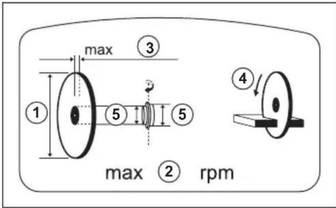
natural_image
Illustration of a person in full protective gear standing next to a first aid kit (no text or symbols visible)natural_image
Simple line drawing of a vehicle or car with two directional arrows indicating movement (no text or symbols)natural_image
Simple line drawing of a vehicle's front view with a diagonal arrow indicating direction (no text or symbols)natural_image
Simple line drawing of a mechanical part with an arrow indicating direction (no text or symbols)natural_image
Simple line drawing of a vehicle or road with directional arrows indicating movement (no text or symbols)natural_image
Simple line drawing of a car's front and side view with an arrow indicating the direction (no text or symbols)natural_image
Simple line drawing of a car's side view with a black arrow indicating direction (no text or symbols)Bladbeschermkap en SmartGuard (optioneel)
natural_image
Diagram of a car's steering wheel and steering wheel assembly (no text or labels)natural_image
Line drawing of a remote control device with a stylized 'H' logo on the side (no text or symbols)natural_image
Illustration of five different types of threaded fasteners or springs, shown in line drawings without any text or symbols.Trillingsdempingssysteem controleren
natural_image
Circular mechanical gear or wheel diagram with directional arrows indicating rotational motion (no text or symbols)
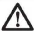
natural_image
Abstract black X-shaped line with a wavy arc above and a small circle below (no text or symbols)natural_image
Diagram of a medical device with two circular components and directional arrows indicating motion or force (no text or symbols)natural_image
Pure diagram of a mechanical component with a black arrow pointing to a circular feature (no text or symbols)natural_image
Diagram of a mechanical device with rotating components and directional arrows (no text or symbols)natural_image
Line drawing of a mechanical device with no visible text or symbolsnatural_image
Technical line drawing of a mechanical device with a tool and gear (no text or symbols)De zaagkop omkeren

natural_image
Technical line drawing of a mechanical device with labeled components and arrows indicating motion (no text or symbols present)natural_image
Technical line drawing of a mechanical assembly with no visible text or symbolsnatural_image
Technical line drawing of a mechanical assembly with no visible text or symbolsnatural_image
Technical line drawing of a mechanical component with no visible text or symbolsnatural_image
Line drawing of a mechanical device with 'Husqenna' branding, no readable text or symbols beyond the labelnatural_image
Simple line drawing of a mechanical device and a globe with directional arrows (no text or symbols)Roterende terugslag
natural_image
Diagram of a medical procedure with a surgical tool and X-shaped cross symbol above a table (no text or labels)natural_image
Simple line drawing of a device with a circular loading symbol (no text or labels)natural_image
Diagram showing a mechanical component interacting with a circular target, with arrows indicating motion or force direction (no text or symbols present)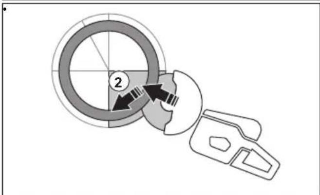
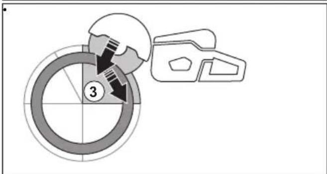
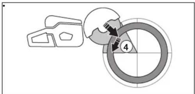
natural_image
Two diagrams showing a cross-shaped object with arrows indicating direction, next to a U-shaped object with a downward arrow (no text or symbols)natural_image
Line drawing of a hand holding a device with a backpack (no text or symbols)natural_image
Diagram of a mechanical device with a rotating shaft and base, showing motion direction (no text or symbols)natural_image
Line drawing of a person using a handheld device to lift or lift an object, wearing boots (no text or symbols)natural_image
Diagram showing two mechanical components with a crossed-out X mark, each with directional arrows indicating movement or force (no text or symbols)natural_image
Line drawing of a person using a power saw to cut a saw (no text or symbols present)natural_image
Illustration of a hand holding a connector with a cable, showing the cable being inserted into a plug (no text or symbols present)natural_image
Simple line drawing of a mechanical part with an arrow indicating direction (no text or symbols)natural_image
Technical line drawing of a mechanical component with no visible text or symbolsDroog zagen
natural_image
Technical line drawing of a mechanical assembly with connectors and a directional arrow (no text or symbols)natural_image
Line drawing of a mechanical device with hands operating it, no text or symbols presentnatural_image
Simple line drawing of a vehicle or container with an arrow indicating direction (no text or symbols)natural_image
Technical line drawing of a mechanical assembly with no visible text or symbolsnatural_image
Technical line drawing of a mechanical component with arrows indicating assembly or force direction (no text or symbols present)natural_image
Technical line drawing of a mechanical component with no visible text or symbolsnatural_image
Line drawing of a mechanical device with a tool inserted, no text or symbols presentnatural_image
Technical line drawing of a mechanical tool or device with no visible text or symbolsnatural_image
Technical line drawing of a mechanical assembly with no visible text or symbolsnatural_image
Technical line drawing of a mechanical assembly with no visible text or symbolsnatural_image
Technical line drawing of a mechanical assembly with no visible text or symbolsnatural_image
Symbol of a trash bin crossed with no text or labels, representing waste sorting or disposal (no text present)
natural_image
Symbol of a trash bin crossed with a diagonal line, no text or labels presentTechnische gegevens
Technische gegevens
Original instructions
Originalanweisungen


- Introduction
- Product description
- Intended use
- Product overview K 7000
- Product overview K 7000 SmartGuard
- Symbols on the product
- Type plate
- Product liability
- Safety
- Safety definitions
- General power tool safety warnings
- Work area safety
- Electrical safety
- Personal safety
- Power tool use and care
- Service
- Cut-off machine safety warning
- Kickback and related warnings
- General safety instructions
- Safety instructions for operation
- Personal protective equipment
- Vibration safety
- Safety devices on the product
- Power trigger lockout and ON/OFF valve for the water
- To do a check of the power trigger lockout
- Blade guard and SmartGuard (Optional)
- To examine the blade and the blade guard
- To do a check of the SmartGuard
- Start and overload protection
- Vibration damping system
- To do a check of the vibration damping system
- Safety instructions for maintenance
- Assembly
- Cutting blades
- Diamond blades
- Cutting blades for handheld high speed power cutters
- Cutting blade vibration
- To sharpen the cutting blade
- Diamond blades for wet cutting
- Diamond blades for dry cutting
- Diamond blade - requirements
- Toothed blades
- To examine the spindle shaft and the flange washers
- To do a check of the arbor bushing
- To examine the direction of rotation of the cutting blade
- To install the cutting blade
- To reverse the cutting head
- Operation
- Kickback
- Reactive force
- Kickback zone
- Rotational kickback
- Climbing kickback
- Pinching kickback
- Pipe cutting
- To cut in smaller pipes
- To cut in larger pipes
- To prevent a kickback
- To do before you start the product
- To decrease dust during operation
- Basic working techniques
- Basic working techniques with K 7000 SmartGuard
- To do a check of the RCD 3 phase
- To connect the water supply
- To dry cut
- To start the product
- To stop the product
- Maintenance
- Maintenance schedule
- To clean externally
- To do a general inspection
- To adjust the tension of the drive belt
- To replace the drive belt
- Transportation, storage and disposal
- Transportation and storage
- Disposal
- Technical data
- Declaration of Conformity
- EU Declaration of Conformity
- UK Declaration of Conformity
- Inhalt
- Blockierung
- Technische Daten
- Précautions relatives aux vibrations
- Rebond rotationnel
- Rebond de grimpée
- Rebond de pincement
- Pour couper à sec
- Inhoud
- Sticker snijuitrusting
- Bladbeschermkap en SmartGuard (optioneel)
- Trillingsdempingssysteem controleren
- De zaagkop omkeren
- Roterende terugslag
- Droog zagen
- Technische gegevens
Brand : HUSQVARNA
Model : K 7000
Category : Saw