
EU70is - Generator Honda - Free user manual and instructions
Find the device manual for free EU70is Honda in PDF.

| Product type | Portable generator |
| Brand | Honda |
| Model | EU70is |
| Dimensions (L × W × H) | 848 × 700 × 721 mm (handles raised: 1198 × 700 × 721 mm) |
| Dry weight | 118.1 kg (with battery) |
| Engine type | Single cylinder 4-stroke, overhead valve (GX390T2) |
| Displacement | 389 cm³ |
| Fuel | Unleaded gasoline (octane rating ≥ 89), E10 max 10% ethanol |
| Fuel tank capacity | 19.2 L |
| Engine oil | SAE 10W-30 (API SE or higher), capacity 1.1 L |
| Rated power | 5.5 kVA (230 V, 23.9 A) |
| Maximum power | 7.0 kVA |
| Frequency | 50 Hz |
| AC outlets | 2 × 230 V 16 A, 1 × 230 V 30 A (according to type) |
| Parallel operation | Possible (two EU70is, optional kit) |
| Eco-Throttle technology | Yes (automatic rpm reduction) |
| Sound level (guaranteed) | 90 dB(A) (Eco-Throttle running) |
| Ignition system | Fully transistorized ignition |
| Battery | 12 V, 11.2 Ah (lead-acid) |
| Safety | Oil Alert, overload protection, RCBO differential circuit breaker recommended |
| Maintenance | Oil check, air filter, spark plug, oil drain, spark arrester |
| General information | User manual in French, 380 pages, manufacturer warranty |
Frequently Asked Questions - EU70is Honda
User questions about EU70is Honda
0 question about this device. Answer the ones you know or ask your own.
Ask a new question about this device
Download the instructions for your Generator in PDF format for free! Find your manual EU70is - Honda and take your electronic device back in hand. On this page are published all the documents necessary for the use of your device. EU70is by Honda.
USER MANUAL EU70is Honda
natural_image
Line drawing of a portable electrical organizer with wheels and control panel (no text or symbols)OWNER'S MANUAL MANUEL DE L'UTILISATEUR BEDIENUNGSANLEITUNG MANUALE DELL'UTENTE
Honda EU70is
OWNER'S MANUAL
Original instructions
MANUEL DE L'UTILISATEUR
Notice originale
BEDIENUNGSANLEITUNG
Exhaust contains poisonous carbon monoxide gas that can build up to dangerous levels in closed areas.
Breathing carbon monoxide can cause unconsciousness or death.
Never run the generator in a closed, or even partly closed area where people may be present.
Keep this owner's manual handy so that you can refer to it at any time. This owner's manual is considered a permanent part of the generator and should remain with the generator if resold.
The information and specifications included in this publication were in effect at the time of approval for printing. Honda Motor Co., Ltd. reserves the right, however, to discontinue or change specifications or design at any time without notice and without incurring any obligation whatsoever.
The illustration may vary according to the type.
INTRODUCTION
Congratulations on your selection of a Honda generator. We are certain you will be pleased with your purchase of one of the finest generators on the market.
We want to help you get the best results from your new generator and to operate it safely. This manual contains all the information on how to do that; please read it carefully.
As you read this manual, you will find information preceded by a NOTICE symbol. That information is intended to help you avoid damage to your generator, other property, or the environment.
We suggest you read the warranty policy to fully understand its coverage and your responsibilities of ownership.
When your generator needs scheduled maintenance, keep in mind that your Honda servicing dealer is specially trained in servicing Honda generators. Your Honda servicing dealer is dedicated to your satisfaction and will be pleased to answer your questions and concerns.
Best Wishes, Honda Motor Co., Ltd.
A FEW WORDS ABOUT SAFETY
Your safety and the safety of others are very important. And using this generator safely is an important responsibility.
To help you make informed decisions about safety, we have provided operating procedures and other information on labels and in this manual. This information alerts you to potential hazards that could hurt you or others.
Of course, it is not practical or possible to warn you about all the hazards associated with operating or maintaining a generator. You must use your own good judgment.
You will find important safety information in a variety of forms, including:
- Safety Labels — on the generator.
- Safety Messages — preceded by a safety alert symbol ⚠️ and one of three signal words, DANGER, WARNING, or CAUTION.
These signal words mean:

You WILL be KILLED or SERIOUSLY HURT if you don't follow instructions.

You CAN be KILLED or SERIOUSLY HURT if you don't follow instructions.

You CAN be HURT if you don't follow instructions.
- Safety Headings — such as IMPORTANT SAFETY INFORMATION.
- Safety Section — such as GENERATOR SAFETY.
- Instructions — how to use this generator correctly and safely.
This entire book is filled with important safety information — please read it carefully.
CONTENTS
GENERATOR SAFETY 6
IMPORTANT SAFETY INFORMATION ......6
Operator Responsibility 6
Carbon Monoxide Hazards....7
Electric Shock Hazards....8
Fire and Burn Hazards 8
Refuel With Care 9
Explosion proof 9
Disposal....9
SAFETY LABEL LOCATIONS.... 10
CE MARK & NOISE LABEL LOCATIONS ......13
CE MARK & NOISE LABEL.... 13
CONTROLS & FEATURES 14
COMPONENT & CONTROL LOCATIONS.... 14
CONTROLS 16
MAIN Switch 16
ENGINE START Button.... 16
Starter Grip 17
Eco-Throttle Switch.... 17
Parallel Operation Outlets 18
AC Circuit Protectors 18
Folding Handle 20
Maintenance Covers 21
FEATURES 22
Ground Terminal 22
OUTPUT Indicator 23
OVERLOAD ALARM Indicator 23
OIL ALERT/CHECK Indicator 24
i-Monitor 25
Fuel Gauge 28
BEFORE OPERATION 29
ARE YOU READY TO GET STARTED? 29
Knowledge 29
IS YOUR GENERATOR READY TO GO? 29
Check the Engine 30
Battery Maintenance Cover 30
OPERATION.... 31
SAFE OPERATING PRECAUTIONS 31
STARTING THE ENGINE 33
STOPPING THE ENGINE 36
STARTING THE ENGINE with REMOTE CONTROL (Optional part)... 37
STOPPING THE ENGINE with REMOTE CONTROL (Optional part)... 38
AC OPERATION.... 39
AC Applications 41
AC Parallel Operation Applications.... 44
ECO-THROTTLE SYSTEM.... 46
STANDBY POWER 47
Connections to a Building's Electrical System 47
System Ground 47
Special Requirements.... 48
SERVICING YOUR GENERATOR 49
THE IMPORTANCE OF MAINTENANCE 49
MAINTENANCE SAFETY 50
Safety Precautions 50
MAINTENANCE SCHEDULE 51
REFUELING....52
FUEL RECOMMENDATIONS.... 53
ENGINE OIL LEVEL CHECK 54
ENGINE OIL CHANGE 55
ENGINE OIL RECOMMENDATIONS 56
AIR CLEANER SERVICE.... 57
FOAM AIR FILTER CLEANING 58
SPARK PLUG SERVICE.... 59
SPARK ARRESTER SERVICE 61
BATTERY SERVICE....62
FUSE 66
STORAGE......67
STORAGE PREPARATION.... 67
Cleaning.... 67
Fuel.... 67
Engine Oil.... 69
Battery 69
STORAGE PRECAUTIONS 70
REMOVAL FROM STORAGE 70
TRANSPORTING 71
TAKING CARE OF UNEXPECTED PROBLEMS 73
ENGINE WILL NOT START.... 73
ENGINE LACKS POWER 74
NO POWER AT THE AC RECEPTACLES 74
TECHNICAL INFORMATION.... 75
Serial Number Location 75
Specifications 76
Wiring Diagram 78
Receptacle 79
ASSEMBLY 80
SAFETY 80
The Importance of Proper Assembly 80
Important Safety Precautions.... 81
ASSEMBLY 82
Unpacking 82
Loose Parts 82
Wheel Kit Installation 83
Battery 84
Engine Oil....85
Fuel....85
Battery Voltage.... 86
BEFORE OPERATION 86
OPTIONAL PARTS.... 87
REMOTE CONTROL KIT 87
HANGER KIT 89
Inside back cover
WIRING DIAGRAM ...... Inside back cover
MAJOR Honda DISTRIBUTOR ADDRESSES ...... Inside back cover
"EC Declaration of Conformity"
CONTENT OUTLINE.... Inside back cover
GENERATOR SAFETY
IMPORTANT SAFETY INFORMATION
Honda generators are designed for use with electrical equipment that has suitable power requirements. Other uses can result in injury to the operator or damage to the generator and other property.
Most injuries or property damage can be prevented if you follow all instructions in this manual and on the generator. The most common hazards are discussed below, along with the best way to protect yourself and others.
- Never attempt to modify the generator. It can cause an accident as well as damage to the generator and appliances. Tampering with the engine voids the EU type-approval of this engine.
- Do not connect an extension to the muffler.
- Do not modify the intake system.
- Do not adjust the governor.
- Do not remove the control panel or do not change the wiring of the control panel.
Operator Responsibility
- Know how to stop the generator quickly in case of emergency.
- Understand the use of all generator controls, output receptacles, and connections.
- Be sure that anyone who operates the generator receives proper instruction. Do not let children operate the generator without parental supervision.
- Be sure to observe the instructions in this manual for how to use the generator and maintenance information. Ignoring or improperly following the instructions can cause an accident such as an electric shock, and the condition of the exhaust gas may deteriorate.
- Obey all applicable laws and regulations where the generator is used.
- Gasoline and Oil is toxic. Follow the instructions provided by each manufacturer before use.
- Place the generator on a firm level place before operation.
- Do not operate the generator with any cover removed. You may get your hand or foot caught in the generator and it may cause accident.
- Consult your authorized Honda dealer for disassembly and service of the generator that are not covered in this manual.
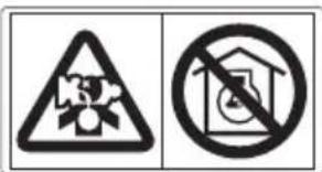
Carbon Monoxide Hazards
A generator's exhaust contains toxic carbon monoxide, which you cannot see or smell. Breathing carbon monoxide can KILL YOU IN MINUTES. To avoid carbon monoxide poisoning, follow these instructions when operating a generator:
- Only run a generator OUTSIDE, far away from windows, doors, and vents.
- Never operate a generator inside a house, garage, basement, crawl space, or any enclosed or partially enclosed space.
- Never operate a generator near open doors or windows.
- Get fresh air and seek medical attention immediately if you suspect you have inhaled carbon monoxide.
Early symptoms of carbon monoxide exposure include headache, fatigue, shortness of breath, nausea, and dizziness. Continued exposure to carbon monoxide can cause loss of muscular coordination, loss of consciousness, and then death.
Electric Shock Hazards
The generator produces enough electric power to cause a serious shock or electrocution if misused.
- Do not use in wet conditions. Keep the generator dry.
- Do not use in the rain or snow.
- Do not use near a pool or a sprinkler system.
- Do not use when your hands are wet.
- If the generator is stored outdoors, unprotected from the weather, all of the electrical components on the control panel before each use. Moisture or ice can cause a malfunction or short circuit in electrical components that could result in electrocution.
- Do not connect to a building's electrical system unless an isolation switch has been installed by a qualified electrician.
- For parallel operation, use only a Honda approved parallel kit (optional equipment) when connecting one EU70is to another EU70is generator.
- Never connect different generator models.
Fire and Burn Hazards
Do not use the generator in areas with a high risk of fire.
The exhaust system gets hot enough to ignite some materials.
- Keep the generator at least 1 meter (3 feet) away from buildings and other equipment during operation.
- Do not enclose the generator in any structure.
- Keep flammable materials away from the generator.
Some parts of the internal combustion engine are hot and may cause burns. Pay attention to the warnings on the generator.
The muffler becomes very hot during operation and remains hot for a while after stopping the engine. Be careful not to touch the muffler while it is hot. Let the engine cool before storing the generator indoors.
Do not pour the water directly on the generator to put out the fire when it occurs. Use an appropriate fire extinguisher specially designed for electric fire or oil fire.
If you inhale fumes produced by an accidental fire with the generator, consult a doctor and have medical treatment immediately.
Refuel With Care
Gasoline is extremely flammable, and gasoline vapor can explode.
- Do not refuel during operation.
- Allow the engine to cool if it has been in operation.
- Refuel only outdoors in a well-ventilated area and on a level surface.
- Never smoke near gasoline, and keep other flames and sparks away.
- Do not overfill the fuel tank.
- Make sure that any spilled fuel has been wiped up and cleaned before starting the engine.
- Always store gasoline in an approved container.
Explosion proof
This generator is not compliant with explosion proof.
Disposal
To protect the environment, do not dispose of the used generator, battery, engine oil, etc. carelessly by leaving them in the waste. Observe the local laws or regulations or consult your authorized Honda generator dealer to dispose of these parts.
Please dispose of used motor oil in a manner that is compatible with the environment. We suggest you take it in a sealed container to your local service station for reclamation. Do not throw it in the trash or pour it on the ground.
An improperly disposed battery can hurt the environment. Always confirm local regulations for battery disposal. Contact your Honda servicing dealer for a replacement.
Disposing of generator
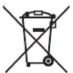
Do not dispose of electric equipment together with household waste material. If electrical appliances are disposed of in landfills or dumps, substances can leak and react and enter into the foodchain, damaging your health and well-being. For further information on the disposal of this product, please contact your dealer or your nearest domestic waste collection service.
SAFETY LABEL LOCATIONS
These labels warn you of potential hazards that can cause serious injury. Read them carefully. If a label comes off or becomes hard to read, contact your Honda servicing dealer for a replacement.
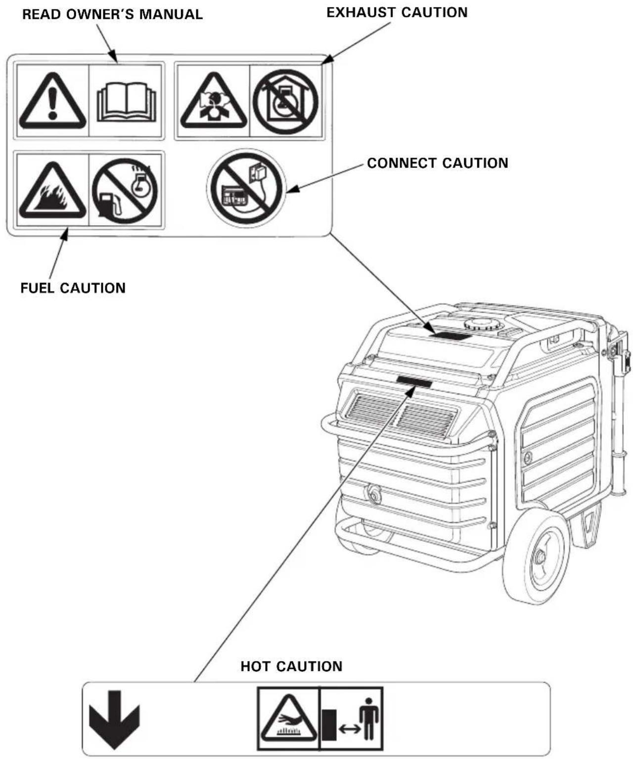
- Honda generator is designed to give safe and dependable service if operated according to instructions. Read and understand the Owner's Manual before operating the generator. Failure to do so could result in personal injury or equipment damage.
- Gasoline is highly flammable and explosive. Turn the engine off and let it cool before refueling.
- Exhaust contains poisonous carbon monoxide, a colorless, odorless gas. Breathing carbon monoxide can cause loss of consciousness and may lead to death. - If you run the generator in an area that is confined, or even partially enclosed area, the air you breathe could contain a dangerous amount of exhaust gas. - Never run your generator inside a garage, house or near open windows or doors.
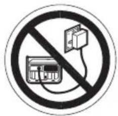
- Improper connections to a building's electrical system can allow current from the generator to backfeed into the utility lines.
Such backfeed may electrocute utility company workers or others who contact the lines during a power outage, and the generator may explode, burn, or cause fires when utility power is restored.
Consult the utility company or a qualified electrician prior to making any power connections.
- A hot exhaust system can cause serious burns. Avoid contact if the engine has been running.
CE MARK & NOISE LABEL LOCATIONS
CE MARK & NOISE LABEL
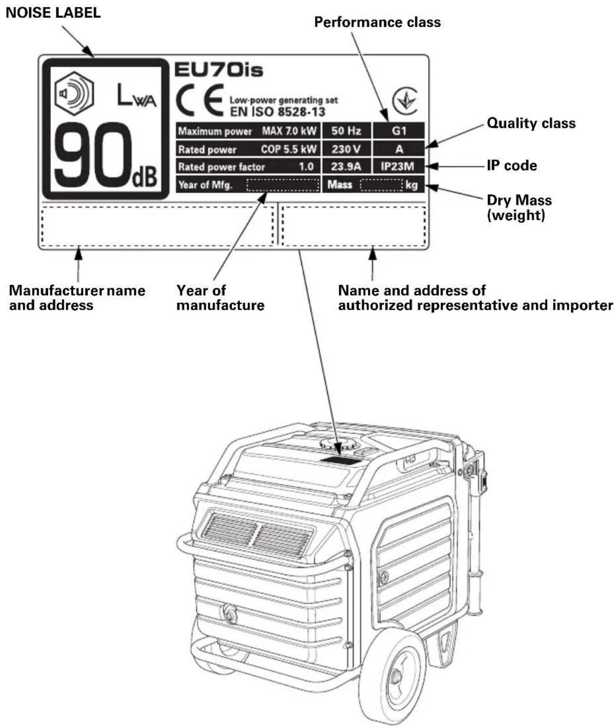
Name and address of manufacturer, authorized representative and importer are written in the “EC Declaration of Conformity” CONTENT OUTLINE in this Owner’s Manual.
CONTROLS & FEATURES
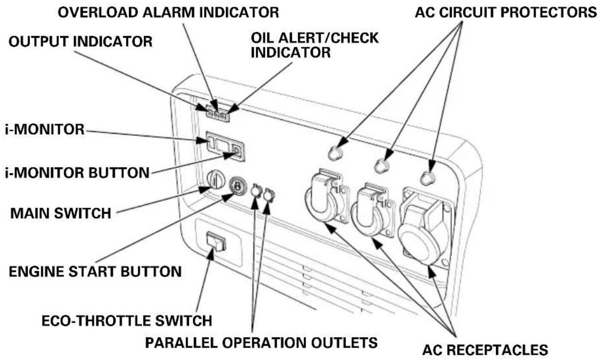
COMPONENT & CONTROL LOCATIONS
Use the illustrations on these pages to locate and identify the most frequently used controls.
GWT type
FT type ITT type
CONTROLS
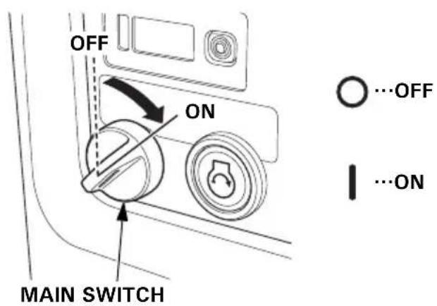
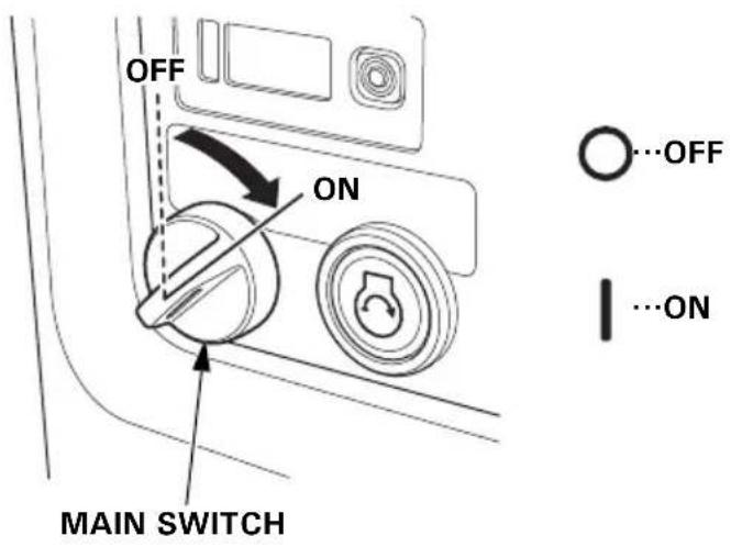
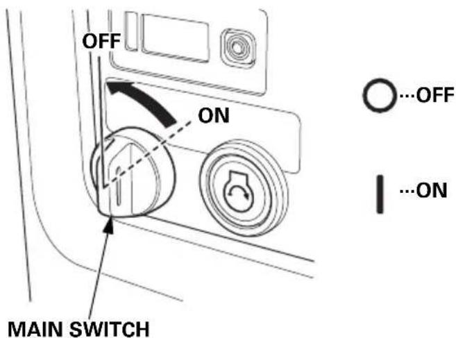
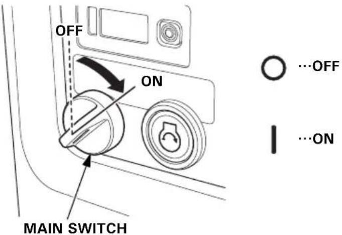
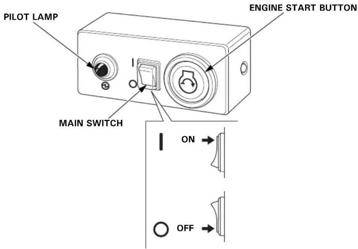
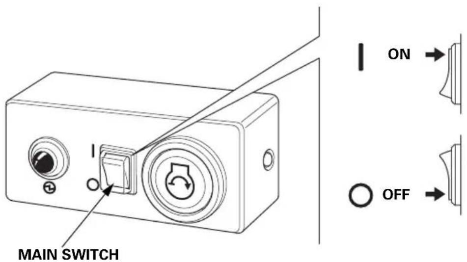
MAIN Switch
The MAIN switch controls the ignition system.
OFF – Stops the engine. The main switch key can be removed/inserted.
ON – Running position, and for starting with the ENGINE START button or recoil starter, and for using the remote control kit (optional parts).
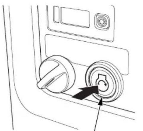
ENGINE START Button
With the MAIN switch in the ON position, press and release the ENGINE START button to start the engine.
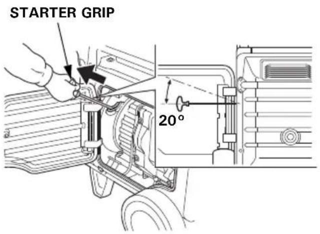
Starter Grip
Used when the battery voltage is too low to turn the starter motor. Pulling the starter grip operates the recoil starter to start the engine.
NOTICE
- Do not exceed 20 degrees from horizontal when pulling the starter grip.
- Do not allow the starter grip to snap back against the engine. Return it gently to prevent damage to the starter.
- Do not let the starter rope rub against the generator body, or the rope will wear out prematurely.

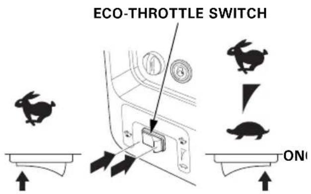
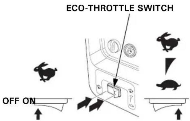
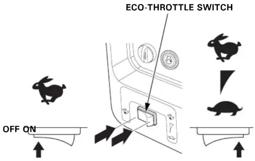
Eco-Throttle Switch
The Eco-Throttle system automatically reduces engine speed when all loads are turned off or disconnected. When appliances are turned on or reconnected, the engine returns to the proper speed to power the electrical load.
If high electrical loads are connected simultaneously, turn the Eco-Throttle switch to the OFF position to reduce voltage changes.
ON – Recommended to minimize fuel consumption and further reduce noise levels when a reduced load or no load is applied to the generator.
OFF – The Eco-Throttle system does not operate. Generator operates at full speed.
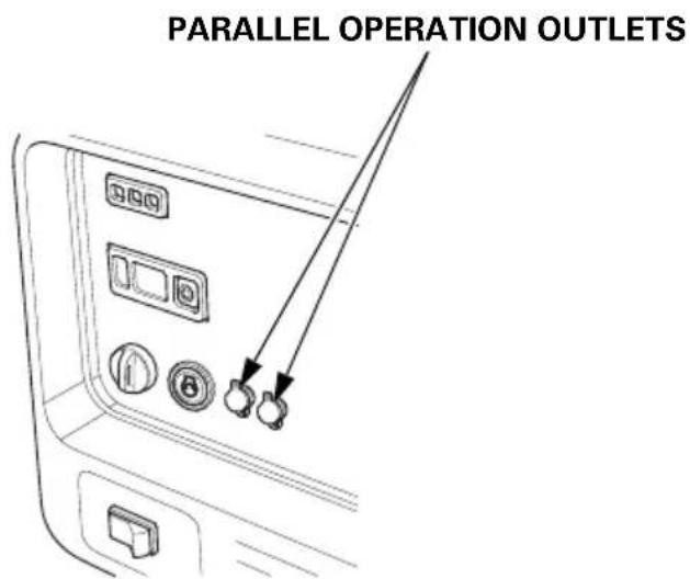
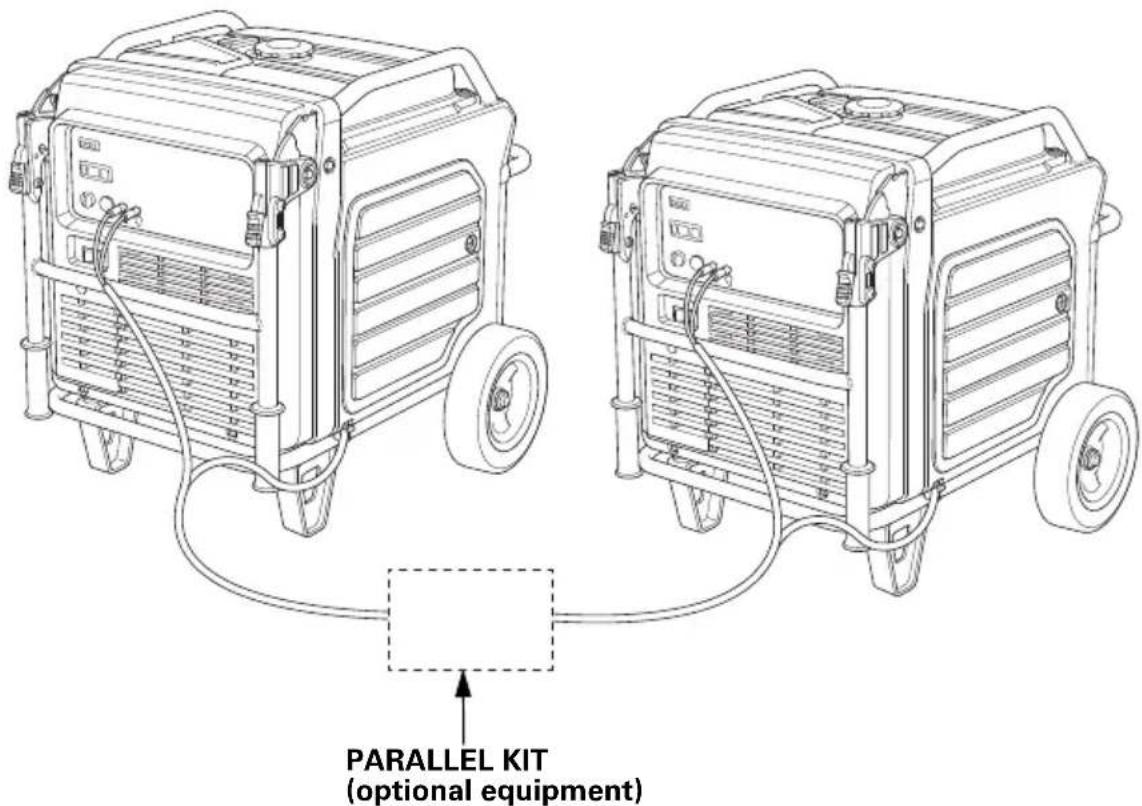
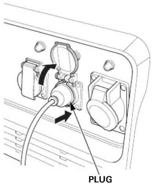
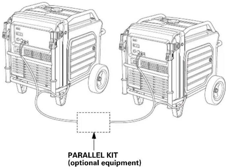
Parallel Operation Outlets
These outlets are used for connecting the EU70is to another EU70is generator for parallel operation (see page 42). A Honda approved parallel kit (optional equipment) is required for parallel operation. This kit can be purchased from your servicing dealer.
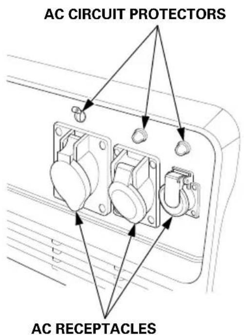
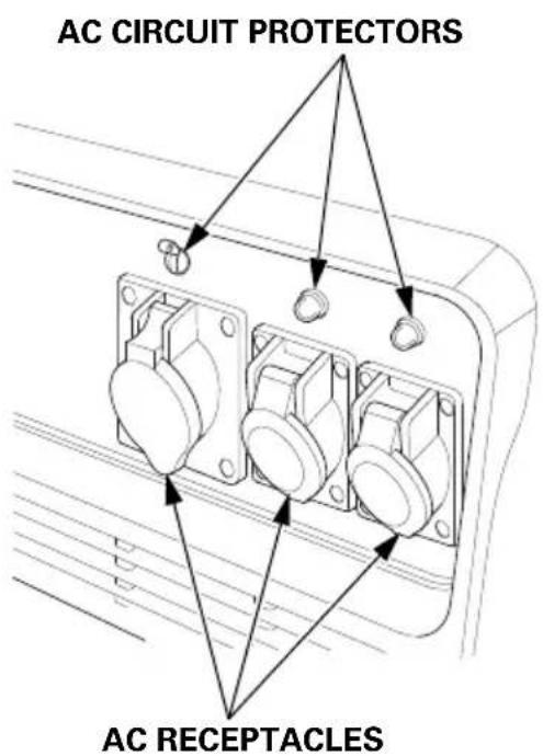
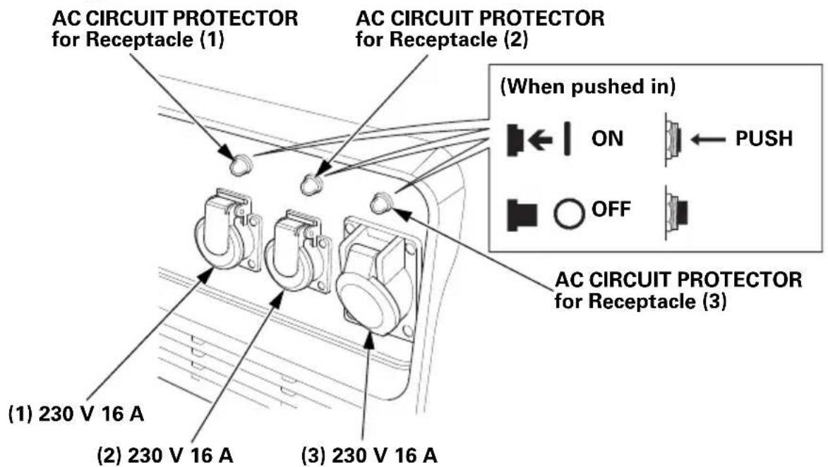
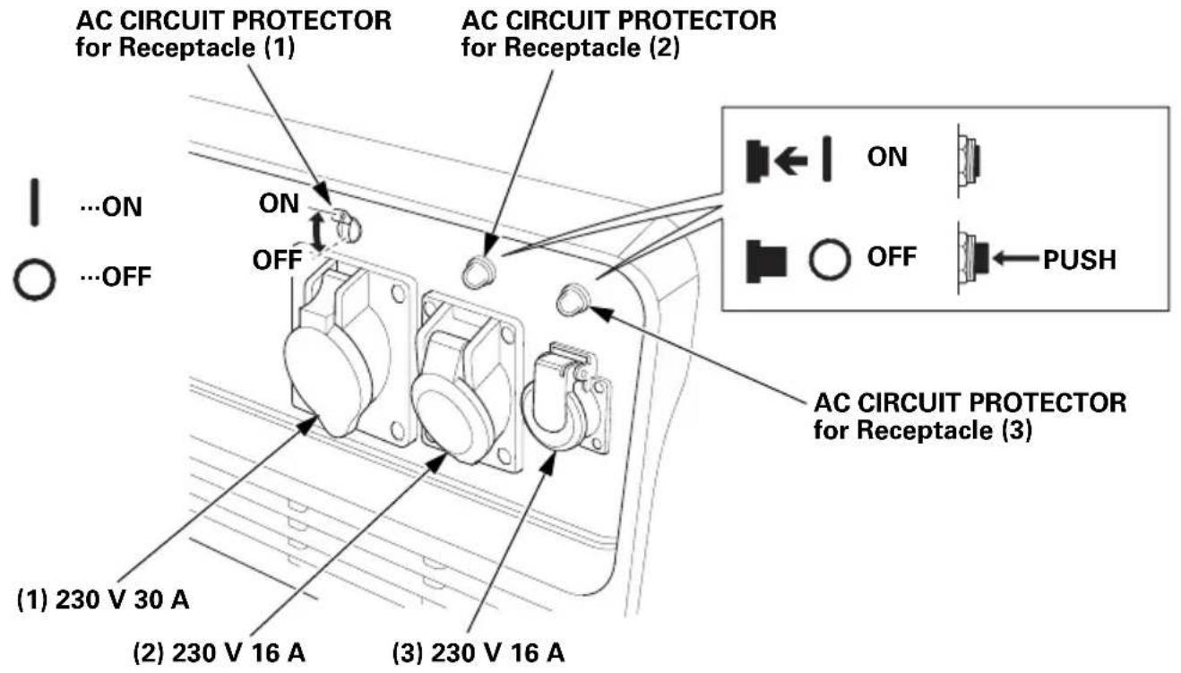
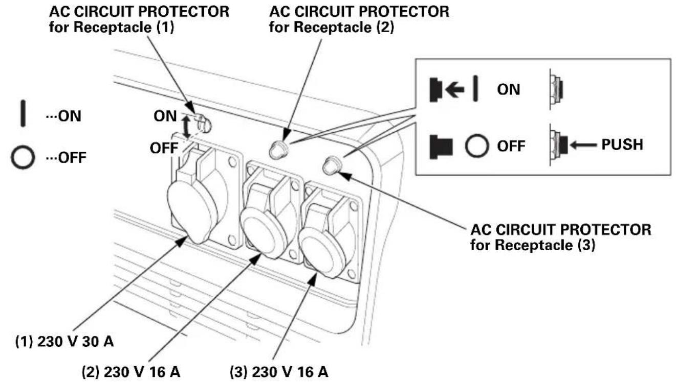
AC Circuit Protectors
The AC circuit protector will automatically switch OFF if there is a short circuit or a significant overload of the generator at each receptacle. If an AC circuit protector switches OFF automatically, check that the appliance is working properly and does not exceed the rated load capacity of the circuit before resetting the AC circuit protector ON by pushing the push button in.
GWT type
FT type
ITT type
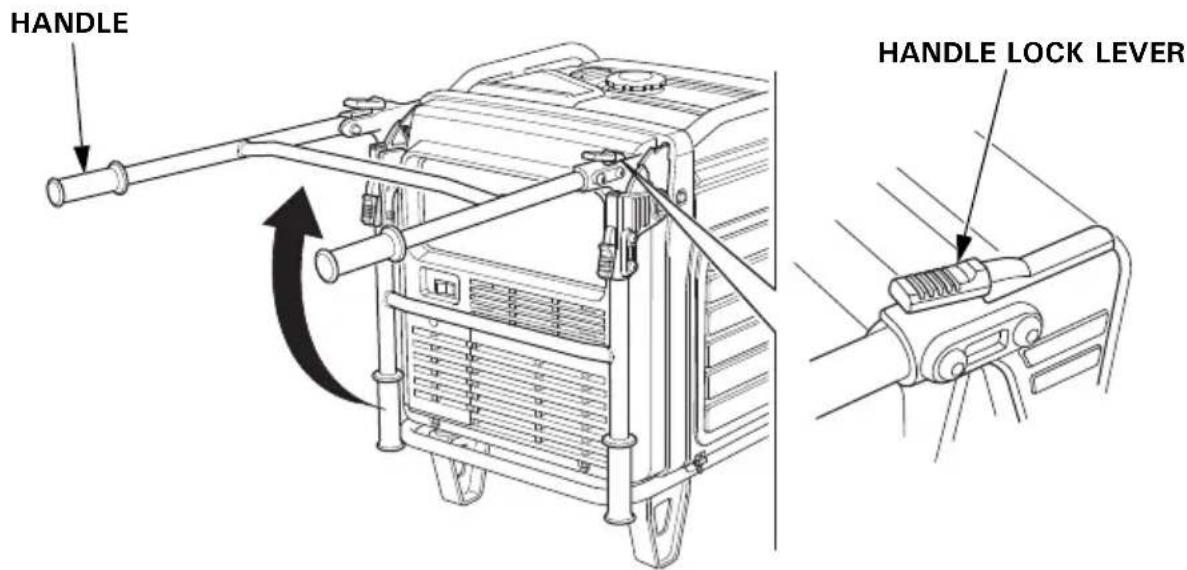
Folding Handle
The foldable handle makes the generator easy to push and should be folded when the generator is stationary. Do not rest objects on the extended handle.
To Extend The Handle
Lift handle upward. Lock levers will lock and secure the handle into place.
To Fold The Handle
- Press both handle lock levers downward.
- Lower the handle.
Maintenance Covers
Maintenance cover location.
• Engine oil level check
- Engine oil change
- Use recoil starter
- Spark plug inspection/replacement
• Air cleaner inspection/cleaning
Push the cover closed and turn the latch.
Be sure the maintenance covers are closed while the generator is running.
NOTICE
Running the generator with maintenance cover(s) open will adversely affect the engine performance, and will cause the generator to overheat.
To open:
Turn the latch 90° counterclockwise.
To close:
Turn the latch 90^ clockwise to lock while pushing the cover.
FEATURES
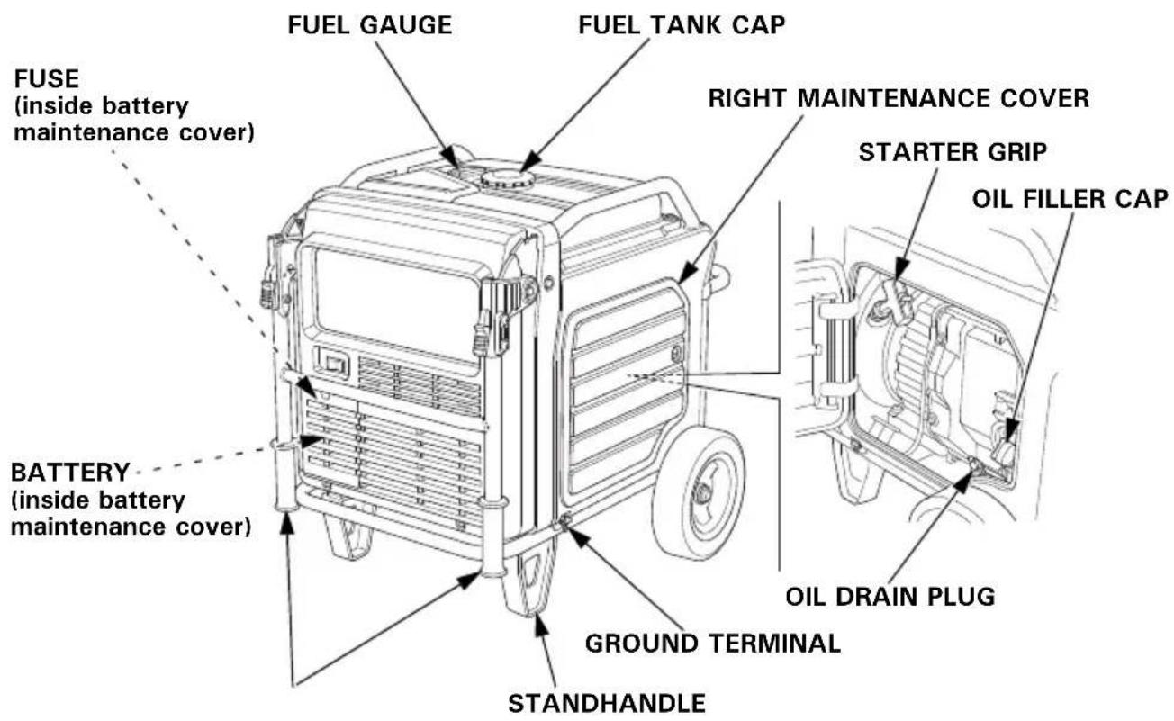
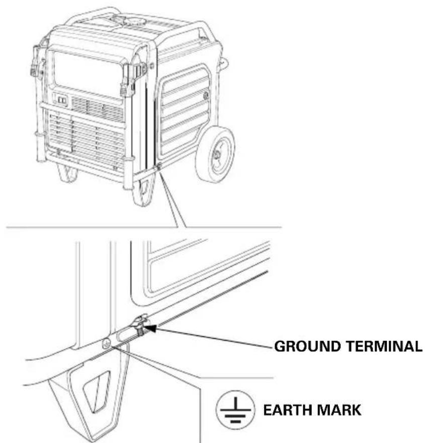
Ground Terminal
The ground terminal is connected to the frame of the generator, the metal non-current-carrying parts of the generator, and the ground terminals of each receptacle.
Before using the ground terminal, consult a qualified electrician, electrical inspector, or local agency having jurisdiction for local codes or ordinances that apply to the intended use of the generator.
The generator produces enough electric power to cause a serious shock or electrocution if misused.
Be sure to ground the generator when the connected appliance is grounded.
To ground the terminal of the generator, use a copper wire with same or larger diameter than the cord of the connected appliance.
Use extension cord set with ground conductor when connecting an appliance with ground conductor.
To identify the Ground pin in the plug, see Receptacle page 79.
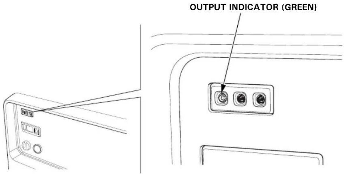
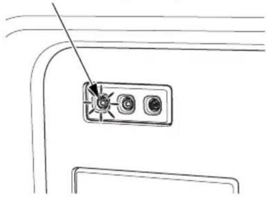
OUTPUT Indicator
The green OUTPUT indicator is illuminated when the generator is operating normally. It indicates that the generator is producing electrical power at the receptacles.
OVERLOAD ALARM Indicator
If the generator is overloaded, or if there is a short circuit in a connected appliance, or if the inverter is overheated, the red OVERLOAD ALARM indicator will go ON. When the generator is operating overloaded, the red OVERLOAD ALARM indicator will stay ON and, after about five seconds, current to the connected appliance(s) will shut off, and the green OUTPUT indicator will go OFF.
OVERLOAD ALRAM INDICATOR (RED)
natural_image
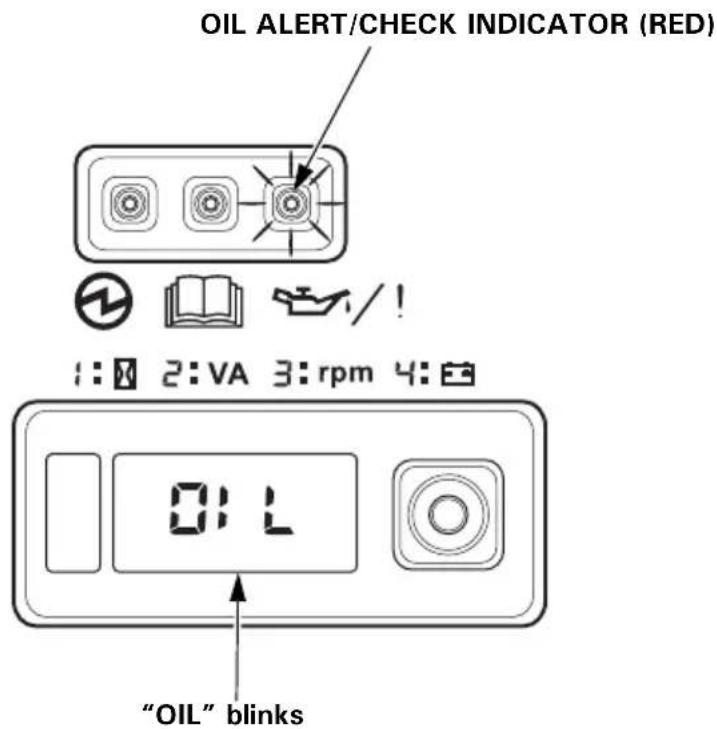
Line drawing of a device panel with three buttons and an arrow pointing to it (no text or symbols)OIL ALERT/CHECK Indicator
The Oil Alert system is designed to prevent engine damage caused by an insufficient amount of oil in the crankcase. Before the oil level in the crankcase can fall below a safe limit, the OIL ALERT/CHECK indicator comes ON, and the Oil Alert system will automatically stop the engine (the MAIN switch will remain in the ON position).
The i-Monitor display will blink “OIL” on the screen and the OIL ALERT/CHECK indicator will illuminate.
If the engine stops or the OIL ALERT/CHECK indicator comes ON when you press the ENGINE START button or pull the starter grip, check the engine oil level (see page 54) before troubleshooting in other areas.
Even when oil is added to the engine, the generator will not restart until the OIL ALERT/CHECK indicator is reset. To reset the OIL ALERT/CHECK indicator, turn the MAIN switch to the OFF position, add the proper amount of oil (see page 54), and then turn the MAIN switch back to the ON position.
If the OIL ALERT/CHECK indicator blinks, consult your servicing dealer.
i-Monitor
The i-Monitor is a user interface that allows the operator to view (when the generator is running) total operating time in hours, generator output, engine RPM, battery voltage, and error messages. The different display modes are selected by pressing the i-Monitor button.
i-Monitor at Startup
During start up, the i-Monitor display and all three indicators will simultaneously blink once. The condition of the i-Monitor display and all three indicators can be checked. Once the generator is running, the green OUTPUT indicator and the i-Monitor display will remain lit.
Display Backlight Flashes
If the key is left in the ON position for over 30 seconds without starting the engine, the display will start to flash.
i-Monitor Display
The i-Monitor display is divided into two screens. The single-digit screen displays the i-Monitor mode, which is represented by a number 1 through 4. The four-digit screen displays the four mode values or any activated error messages.
i-Monitor Display Mode 1 – Total Operating Hours
This mode displays the total operating hours of the generator. When the generator is running, the total operating time accumulates. If the total operating time is less than one hour, the numeric display will be “0.” When the operating time is one hour or greater, the display will be “1” or “2” and so on. Base the generator’s maintenance schedule on the accumulated time displayed.
i-Monitor Display Mode 2 – Power Output
This mode displays an approximate generator output on the display screen. The output is expressed in VA (volt-amperes). The output value is not an exact measurement and should be regarded as a reference only. Power output will not display until a load is connected to the generator.
i-Monitor Display Mode 3 – Engine RPM
When the i-Monitor is in this mode, the engine's speed, expressed in revolutions-per-minute (RPM), is displayed.
i-Monitor Display Mode 4 – Battery Voltage
This mode displays the battery condition, expressed in Volts DC.
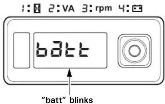
i-Monitor Low Battery Message
If the ENGINE START button is pressed and “batt” is blinked on the i-Monitor display, the battery voltage is too low to operate the engine’s electric starter. Use the recoil starter to start the generator. Have the battery recharged and checked (see page 65).
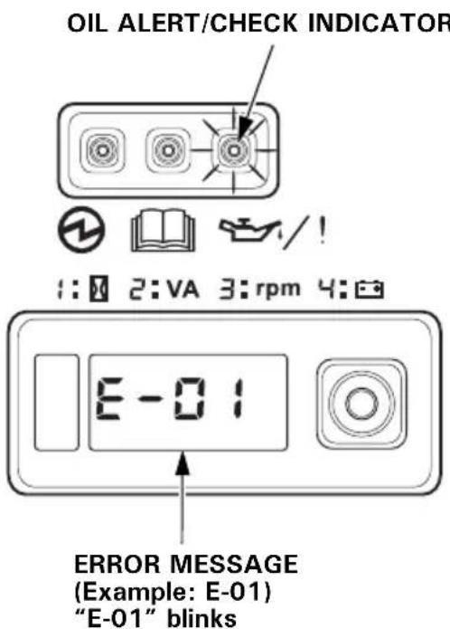
i-Monitor System Error Messages
If the generator has a system malfunction, it will blink an error message on the i-Monitor display. During remote control operation, an E-01 error message may display if the ENGINE START button is pressed for more than 10 seconds. With an E-01 error message, the engine will stay running and the electrical output may stay constant.
Normal remote control operation will be restored after the E-01 error message clears automatically. If the E-01 error message does not clear automatically or if any other error message displays, contact your servicing dealer.
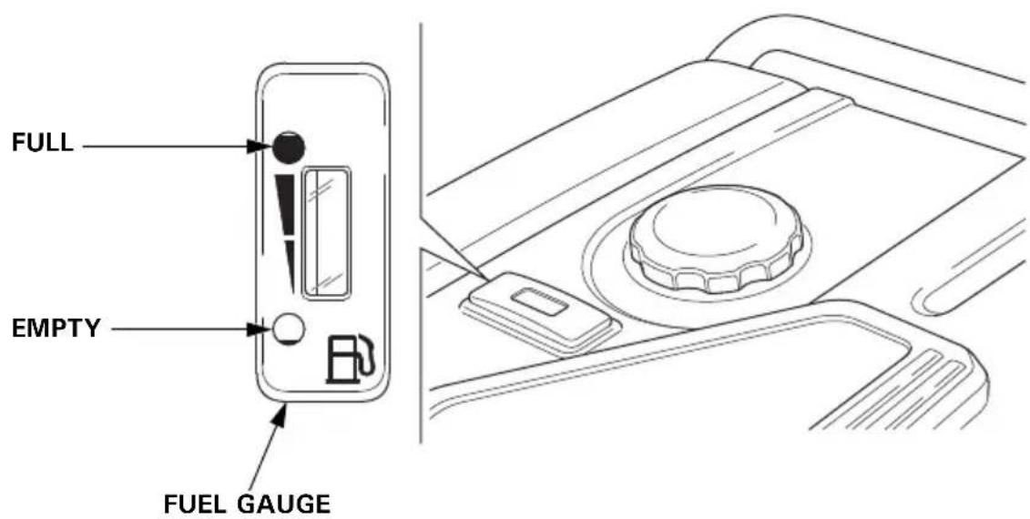
Fuel Gauge
The fuel gauge is a mechanical device that measures the fuel level in the tank. The red indicator in the window will reference the level in relation to full or empty. To provide increased operating time, start with a full tank before operation. Check the fuel level with the generator on a level surface. Always refuel with the engine OFF and cool.
BEFORE OPERATION
ARE YOU READY TO GET STARTED?
Your safety is your responsibility. A little time spent in preparation will significantly reduce your risk of injury.
Knowledge
Read and understand this manual. Know what the controls do and how to operate them.
Familiarize yourself with the generator and its operation before you begin using it. Know how to quickly shut off the generator in case of an emergency.
If the generator is being used to power appliances, be sure that they do not exceed the generator's load rating (see page 41).
IS YOUR GENERATOR READY TO GO?
For your safety, to ensure compliance with environmental regulations, and to maximize the service life of your equipment, it is very important to take a few moments before you operate the generator to check its condition. Be sure to take care of any problem you find, or have your servicing dealer correct it, before you operate the generator.
WARNING
Failure to properly maintain this generator, or failing to correct a problem before operation, could result in a significant malfunction.
Some malfunctions can cause serious injuries or death.
Always perform a pre-operation inspection before each operation and correct any problems.
To prevent a possible fire, keep the generator at least 1 meter (3 feet) away from building walls and other equipment during operation. Do not place flammable objects close to the engine.
Before beginning your pre-operation checks, be sure the generator is on a level and firm surface and the MAIN switch is in the OFF position.
Check the Engine
- Before each use, look around and underneath the engine for signs of oil or gasoline leaks.
- Check the engine oil level (see page 54). A low engine oil level will cause the Oil Alert system to shut down the engine.
- Check the air filters (see page 57). Dirty air filters will restrict air flow to the fuel system, reducing engine and generator performance.
- Check the fuel level (see page 52). Starting with a full tank will help to eliminate or reduce operating interruptions for refueling.
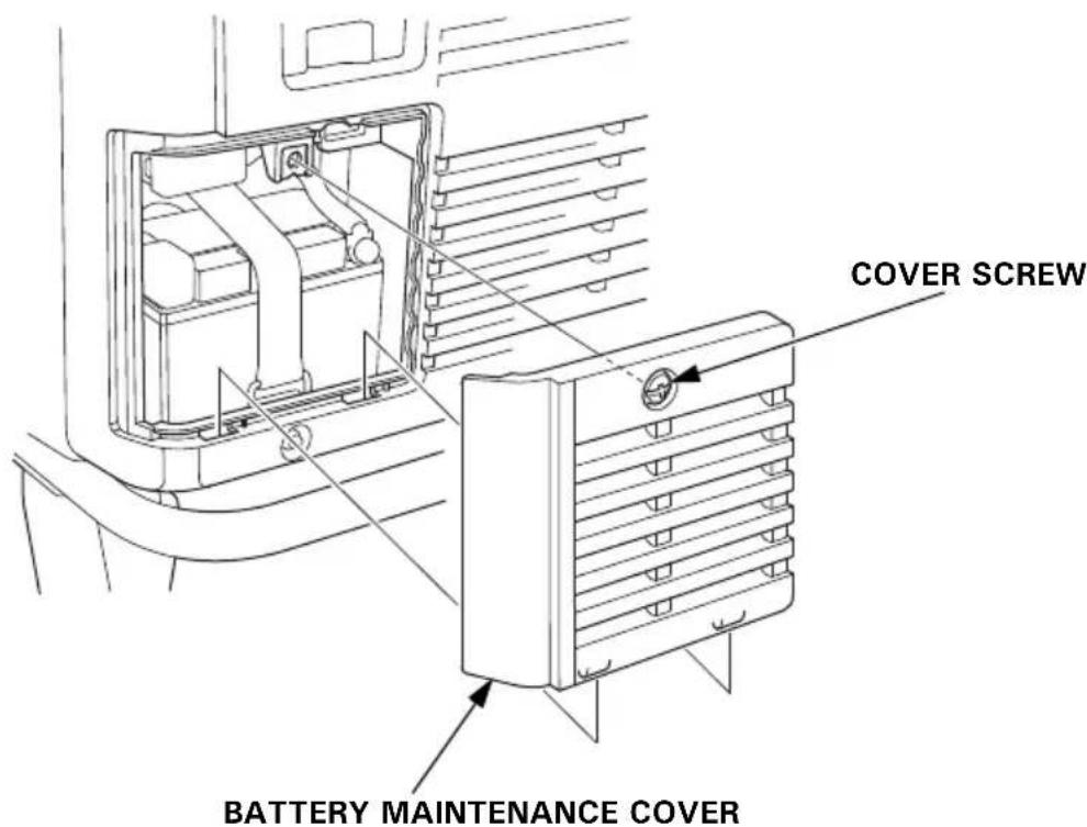
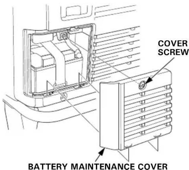
Battery Maintenance Cover
Never operate the generator with the battery maintenance cover open, as poor engine and generator performance will result.
natural_image
Line drawing of a portable gas generator with wheels and ventilation slots (no text or symbols)BATTERY MAINTENANCE COVER
OPERATION
SAFE OPERATING PRECAUTIONS
Before operating the generator for the first time, review chapters GENERATOR SAFETY (see page 6) and BEFORE OPERATION (see page 29).
For your safety, do not operate the generator in an enclosed area such as a garage. Your generator's exhaust contains poisonous carbon monoxide gas that can collect rapidly in an enclosed area and cause illness or death.
WARNING
Exhaust contains poisonous carbon monoxide gas that can build up to dangerous levels in closed areas.
Breathing carbon monoxide can cause unconsciousness or death.
Never run this product's engine in a closed, or even partly closed area where people may be present.
Before connecting an AC appliance or power cord to the generator:
- Use grounded 3-prong extension cords, tools, and appliances, or double-insulated tools and appliances.
- Inspect cords and plugs, and replace if damaged.
- Make sure that the appliance is in good working order. Faulty appliances or power cords can create a potential for electric shock.
- Make sure the electrical rating of the tool or appliance does not exceed the rated power of the generator or the receptacle being used.
- Operate the generator at least 1 meter (3 feet) away from buildings and other equipment.
- Do not operate the generator in an enclosed structure.
-
Do not place flammable objects close to the engine or locate the generator near flammable materials.
-
Do not exceed the current limit specified for any one receptacle.
- Do not modify or use the generator for other purposes than it is intended for. Also observe the following when using the generator.
- Do not connect an extension to the exhaust pipe.
- When an extension cable is required, be sure to use a tough rubber sheathed flexible cable (IEC 245 or equivalent).
When using an extension cable the resistance value shall not exceed 1.5 . - Limit length of extension cables; 60 m (200 feet) for cables of 1.5 ~mm^2 ( 0.0023 in^2 ) and 100 m (330 feet) for cables of 2.5 ~mm^2 ( 0.0039 in^2 ). Long extension cables will lower usable power due to resistance in the extension cable.
- Keep the generator away from other electric cables or wires such as commercial power supply lines.
Frequency of Use
If your generator will be used on an infrequent or intermittent basis, (more than 4 weeks before next use), please refer to the Battery Service section of the SERVICING YOUR GENERATOR (see page 62) and the Fuel section of the STORAGE chapter (see page 67) for additional information regarding battery and fuel deterioration.
STARTING THE ENGINE
To prevent a possible fire, keep the generator at least 1 meter (3 feet) away from building walls and other equipment during operation. Do not place flammable objects close to the engine.
NOTICE
- Operating this generator less than 1 meter (3 feet) from a building or other obstruction can cause overheating and damage the generator.
- For proper cooling, allow at least 1 meter (3 feet) of empty space above and around the generator.
Keep all cooling holes open and clear of debris, mud, water, etc.
Cooling holes are located on the control panel and the bottom of the generator. If the cooling holes are blocked, the generator may overheat and damage the engine, inverter, or windings.
Refer to SAFE OPERATING PRECAUTIONS on page 31 and perform the IS YOUR GENERATOR READY TO GO? checks (see page 29).
Refer to AC OPERATION (see page 39) for connecting loads to the generator.
-
Make sure that all appliances are disconnected from the AC receptacles.
-
Make sure the Eco-Throttle switch is in the OFF position, or more time will be required for warm-up.
If you wish to use the Eco-Throttle system, turn the Eco-Throttle switch to the ON position after the engine has warmed up for 2 or 3 minutes. - Turn the MAIN switch to the ON position.
- Press and release the ENGINE START button.
The ENGINE START button functions for 5 seconds. As soon as the engine starts, the starter will stop automatically.
If the engine fails to start, wait at least 10 seconds before operating the starter again.
natural_image
Line drawing of a door handle with two circular buttons and a rotary knob, no text or symbols presentENGINE START BUTTON
Do not leave the MAIN switch in the ON position when the generator is not operating or the battery will be drained. Turn the MAIN switch to the OFF position when not in use.
- Use the recoil starter when the battery voltage is too low to turn the starter motor.
a. Turn the MAIN switch to the ON position.
b. Open the right maintenance cover by turning its latch counterclockwise.
c. Pull the starter grip lightly until you feel resistance; then pull briskly in the direction of the arrow as shown.
NOTICE
- Do not exceed 20 degrees from horizontal when pulling the starter grip.
- Do not allow the starter grip to snap back against the engine. Return it gently to prevent damage to the starter.
- Do not let the starter rope rub against the generator body, or the rope will wear out prematurely.
d. Close the right maintenance cover by turning its latch clockwise.
- If you wish to use the Eco-Throttle system, turn the Eco-Throttle switch to the ON position after the engine has warmed up for 2 or 3 minutes.
STOPPING THE ENGINE
To stop the engine in an emergency, simply turn the MAIN switch to the OFF position.
Under normal conditions, use the following procedure.
- Turn off or disconnect all appliances that are connected to the generator.
- Turn the MAIN switch to the OFF position.
- If two generators were connected for parallel operation, disconnect the parallel operation cable after stopping the engines if you do not wish to resume parallel operation.
STARTING THE ENGINE with REMOTE CONTROL (Optional part)
- Turn the MAIN switch of the generator to the ON position.
- Turn the MAIN switch of the remote control to the ON position.
- Press and release the ENGINE START button.
The ENGINE START button functions for 5 seconds. As soon as the engine starts, the starter will stop automatically.
The pilot lamp comes on when the engine starts.
If the engine fails to start, wait at least 10 seconds before operating the starter again.
STOPPING THE ENGINE with REMOTE CONTROL (Optional part)
To stop the engine in an emergency, simply turn the MAIN switch of the remote control to the OFF position.
Under normal conditions, use the following procedure.
- Turn off or disconnect all appliances that are connected to the generator.
- Turn the MAIN switch of the remote control to the OFF position.
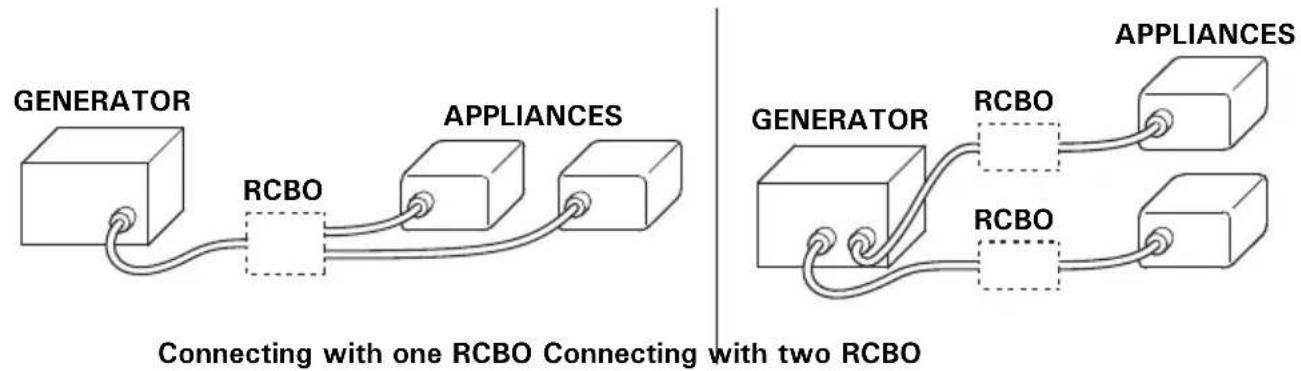
AC OPERATION
Connect a RCBO (Residual current circuit breaker with overload protection) of 30 mA ground fault detection and cut-off of less than 0.4 seconds at more than 30 A of output current, if you are using two or more appliance.
Follow the instructions provided by each RCBO manufacturer before use.
flowchart
graph LR
    A["GENERATOR"] --> B["RCBO"]
    B --> C["APPLIANCES"]
    C --> D["Appliances"]
    style A fill:#f9f,stroke:#333
    style D fill:#bbf,stroke:#333
    note1["Connecting with one RCBO Connecting with two RCBO"]
    note2["GENERATOR"]
    note3["APPLIANCES"]
If an appliance begins to operate abnormally, becomes sluggish, or stops suddenly, turn it off immediately. Disconnect the appliance, and determine whether the problem is in the appliance or the rated load capacity of the generator has been exceeded.
NOTICE
Substantial overloading that continuously lights the red OVERLOAD ALARM indicator may damage the generator. Marginal overloading that temporarily lights the red OVERLOAD ALARM indicator may shorten the service life of the generator.
- Start the engine and make sure the green OUTPUT indicator comes on.
OUTPUT INDICATOR (GREEN)
natural_image
Line drawing of a device panel with three buttons and a pointer (no text or symbols)2.Plug in the appliance.
Most motorized appliances require more than their rated wattage for startup.
If the generator is overloaded, or if there is a short circuit in a connected appliance, or if the inverter is overheated, the red OVERLOAD ALARM indicator will come ON. The red OVERLOAD ALARM indicator will stay ON and, after about five seconds, current to the connected appliance(s) will shut off, and the green OUTPUT indicator will go OFF. Stop the engine and investigate the problem.
Determine if the cause is a short circuit in a connected appliance, an overload, or an overheated inverter. Correct the problem and restart the generator.
Before connecting an appliance to the generator, make sure that it is in good order and that its electrical rating does not exceed that of the generator. Then start the generator and connect the appliance power cord.
When an electric motor is started, the red OVERLOAD ALARM indicator may come on. This is normal if the red OVERLOAD ALARM indicator goes OFF after about five seconds. If the red OVERLOAD ALARM indicator stays ON, consult your servicing dealer.
AC Applications
Before connecting an appliance or power cord to the generator:
- Make sure that it is in good working order. Faulty appliances or power cords can create a potential for electrical shock.
- If an appliance begins to operate abnormally, becomes sluggish, or stops suddenly, turn it off immediately. Disconnect the appliance, and determine whether the problem is the appliance or the rated load capacity of the generator has been exceeded.
Most appliance motors require more than their rated wattage for startup.
Make sure the electrical rating of the tool or appliance does not exceed the maximum power rating of the generator.
Maximum power is:
7.0 kVA
For continuous operation, do not exceed the rated power.
Rated power is:
5.5 kVA
In either case, the total power requirements (VA) of all appliances connected must be considered. Appliance and power tool manufacturers usually list rating information near the model number or serial number.
NOTICE
Substantial overloading will open the circuit protector. Slightly overloading the generator may not switch the circuit protector OFF, but will shorten the service life of the generator.
Before connecting an appliance to either generator, make sure that the appliance is in good working order and that its electrical rating does not exceed that of the receptacle.
Most motorized appliances require more than their electrical rating for startup. When an electric motor is started, the OVERLOAD ALARM indicator (red) may come ON. This is normal if the OVERLOAD ALARM indicator (red) goes OFF within 5 seconds. If the OVERLOAD ALARM indicator (red) stays ON, consult your servicing dealer.
During parallel operation, the Eco-Throttle switch should be in the same position on both generators.
- Connect the parallel operation cable between two EU70is generators following the instructions supplied with the parallel kit.
- Place two generators at least 1 meter (3 feet) away from each other during parallel operation.
• Take care not to slacken the wire toward the starter grip side.
- Do not set the generators with the exhaust side face to face each other.
- Start the engine on each generator and make sure each OUTPUT indicator (green) comes ON.
- Plug in the appliance following the instructions provided with the parallel kit.
- Turn on the appliance.
If the generators are overloaded (see page 45), or if there is a short circuit in a connected appliance, the OVERLOAD ALARM indicators (red) will come ON. The OVERLOAD ALARM indicators (red) will stay ON, and after about five seconds, current to the connected appliance(s) will shut off, and the OUTPUT indicators (green) will go OFF. Stop both engines and investigate the problem.
Determine if the cause is a short circuit in a connected appliance or an overload. Correct the problem and restart the generators.
AC Parallel Operation Applications
Two EU70is generators can be connected together to increase the available power using a parallel kit (optional equipment).
Follow the instructions included with the parallel kit.
Before connecting an appliance or power cord to the generator:
- Make sure that it is in good working order. Faulty appliances or power cords can create a potential for electrical shock.
- If an appliance begins to operate abnormally, becomes sluggish, or stops suddenly, turn it off immediately. Disconnect the appliance, and determine whether the problem is the appliance or the rated load capacity of the generator has been exceeded.
- Never connect different generator models.
- For parallel operation, use only a Honda approved parallel kit (optional equipment) when connecting one EU70is to another EU70is generator.
- Never connect or remove the parallel operation cable when the generator is running.
- For single generator operation, the parallel operation cable must be disconnected from both generators.
Most appliance motors require more than their rated wattage for startup.
Make sure the electrical rating of the tool or appliance does not exceed the maximum power rating of the generator.
Maximum power in parallel operation is:
14.0 kVA (Observe to the Parallel Kit power limit instruction.)
For continuous operation, do not exceed the rated power.
Rated power in parallel operation is:
11.0 kVA (Observe to the Parallel Kit power limit instruction.)
In either case, the total power requirements (VA) of all appliances connected must be considered. Appliance and power tool manufacturers usually list rating information near the model number or serial number.
NOTICE
Substantial overloading that continuously lights the red OVERLOAD ALARM indicator may damage the generator. Marginal overloading that temporarily lights the red OVERLOAD ALARM indicator may shorten the service life of the generator.
ECO-THROTTLE SYSTEM
With the switch in the ON position, engine speed is automatically lowered when loads are reduced, turned off, or disconnected. When appliances are turned on or reconnected, the engine returns to the proper speed to power the electrical load. In the OFF position, the Eco-Throttle system does not operate.
Appliances with large start-up power demands may not allow the engine to reach normal operating rpm when they are connected to the generator. Turn the Eco-Throttle switch to the OFF position and connect the appliance to the generator. If the engine still will not reach normal operating speed, check that the appliance does not exceed the rated load capacity of the generator.
If high electrical loads are connected simultaneously, turn the Eco-Throttle switch to the OFF position to reduce voltage changes.
The Eco-Throttle system is not effective for use with appliances or tools that require only momentary power. If the tool or appliance will be turned ON and OFF quickly, the Eco-Throttle switch should be in the OFF position.
STANDBY POWER
Connections to a Building's Electrical System
Connections for standby power to a building's electrical system must be made by a qualified electrician. The connection must isolate the generator power from utility power, and must comply with all applicable laws and electrical codes.
WARNING
Improper connections to a building's electrical system can allow current from the generator to backfeed into the utility lines.
Such backfeed may electrocute utility company workers or others who contact the lines during a power outage, and the generator may explode, burn, or cause fires when utility power is restored.
Consult the utility company or a qualified electrician prior to making any power connections.
In some areas, generators are required by law to be registered with local utility companies. Check local regulations for proper registration and use procedures.
System Ground
This generator has a system ground that connects generator frame components to ground terminals in the AC output receptacles. The system ground is not connected to the AC neutral wire.
Special Requirements
There may be applicable laws, local codes, or ordinances that apply to the intended use of the generator. Please consult a qualified electrician, electrical inspector, or the local agency having jurisdiction.
- In some areas, generators are required to be registered with local utility companies.
- If the generator is used at a construction site, there may be additional regulations that must be observed.
SERVICING YOUR GENERATOR
THE IMPORTANCE OF MAINTENANCE
Good maintenance is essential for safe, economical, and trouble-free operation. It will also help reduce air pollution.
To help you properly care for your generator, the following pages include a maintenance schedule, routine inspection procedures, and simple maintenance procedures using basic hand tools. Other service tasks that are more difficult or require special tools are best handled by professionals and are normally performed by a Honda technician or other qualified mechanic.
The maintenance schedule applies to normal operating conditions. If you operate your generator under unusual conditions, such as sustained high-load or high-temperature operation, or use it in dusty conditions, consult your servicing dealer for recommendations applicable to your individual needs and use.
WARNING
Failure to properly maintain this generator, or failing to correct a problem before operation, could result in a significant malfunction.
Some malfunctions can cause serious injuries or death.
Always follow the inspection and maintenance recommendations and schedules in this owner's manual.
Remember that an authorized Honda servicing dealer knows your generator best and is fully equipped to maintain and repair it.
To ensure the best quality and reliability, use only new, Honda Genuine parts or their equivalents for repair and replacement.
MAINTENANCE SAFETY
Some of the most important safety precautions follow. However, we cannot warn you of every conceivable hazard that can arise in performing maintenance. Only you can decide whether or not you should perform a given task.
WARNING
Improper maintenance can cause an unsafe condition.
Failure to properly follow maintenance instructions and precautions can cause serious injuries or death.
Always follow the procedures and precautions in this owner's manual.
Safety Precautions
Make sure the engine is off before you begin any maintenance or repairs. This will eliminate several potential hazards:
–Carbon monoxide poisoning from engine exhaust.
Operate outside away from open windows or doors.
-Burns from hot parts.
Let the engine and exhaust system cool before touching.
-Injury from moving parts.
Do not run the engine unless instructed to do so.
- Read the instructions before you begin, and make sure you have the tools and skills required.
- To reduce the possibility of fire or explosion, be careful when working around gasoline. Use only a non-flammable solvent, not gasoline, to clean parts. Keep cigarettes, sparks, and flames away from all fuel-related parts.
MAINTENANCE SCHEDULE
| REGULAR SERVICE PERIOD (3)ITEMPerform at every indicated month or operating hour interval, whichever comes first. | Each use | First month or 20 hrs. | Every 3 months or 50 hrs. | Every 6 months or 100 hrs. | Every year or 300 hrs. | Page | |
| Engine oil Check level o 54 | |||||||
| Change o o 55 | |||||||
| Air cleaner Check o 57 | |||||||
| Clean o (1) 58 | |||||||
| Replace o (*) 57 | |||||||
| Spark plug Check-adjust o 59 | |||||||
| Replace o 59 | |||||||
| Spark arrester | Clean | o | 61 | ||||
| Valve clearance | Check-adjust | o (2) | — | ||||
| Combustion chamber | Clean | After every 1,000 hrs. (2) | — | ||||
| Fuel tank | Clean | Every 2 years or 1,000 hrs. (2) | — | ||||
| Fuel filter | Change | Every 2 years or 1,000 hrs. (2) (4) | — | ||||
| Fuel tube | Check | Every 2 years (Replace if necessary) (2) (4) | — | ||||
NOTE:
(*) Replace paper element type only.
(1) Service more frequently when used in dusty areas.
(2) These items should be serviced by your servicing dealer, unless you have the proper tools and are mechanically proficient. Refer to the Honda shop manual for service procedures.
(3) For commercial use, log hours of operation to determine proper maintenance intervals.
(4) In the event of cracks or fracture in the fuel filter grommet and regulator grommet, replace the part with a new one.
This generator is equipped with a catalytic converter. If the engine is not properly maintained, the catalyst in the muffler may lose effectiveness.
REFUELING
With the engine stopped, check the fuel level gauge. Refill the fuel tank if the fuel level is low.
WARNING
Gasoline is highly flammable and explosive.
You can be burned or seriously injured when handling fuel.
- Stop the engine and let it cool before handling fuel.
- Keep heat, sparks and flame away.
- Handle fuel only outdoors.
- Keep away from your vehicle.
- Wipe up spills immediately.
NOTICE
Fuel can damage paint and plastic. Be careful not to spill fuel when filling your fuel tank. Damage caused by spilled fuel is not covered under warranty.
Refuel in a well-ventilated area before starting the engine. If the engine has been running, allow it to cool. Refuel carefully to avoid spilling fuel.
Do not fill the fuel tank above the upper level mark (red) on the fuel filter.
Never refuel the engine inside a building where gasoline fumes may reach flames or sparks. Keep gasoline away from appliance pilot lights, barbecues, electric appliances, power tools, etc.
Spilled fuel is not only a fire hazard, it causes environmental damage. Wipe up spills immediately.
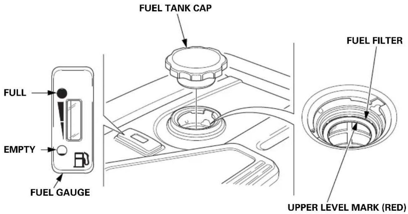
After refueling, reinstall the fuel tank cap securely.
FUEL RECOMMENDATIONS
This engine is certified to operate on regular unleaded gasoline with a Research Octane Number of 89 or higher.
Fuel specification(s) necessary to maintain the performance of the emissions control system: E10 fuel referenced in EU regulation.
Use unleaded gasoline only, or the catalyzer will lose its effectiveness and negatively affect exhaust emissions.
Never use gasoline that is stale, contaminated, or mixed with oil. Avoid getting dirt or water in the fuel tank.
You may use regular unleaded gasoline containing no more than 10% ethanol (E10) or 5% methanol by volume. In addition, methanol must contain cosolvents and corrosion inhibitors.
Use of fuels with content of ethanol or methanol greater than shown above may cause starting and/or performance problems. It may also damage metal, rubber, and plastic parts of the fuel system.
Engine damage or performance problems that result from using a fuel with percentages of ethanol or methanol greater than shown above and leaded gasoline are not covered under warranty.
If your equipment will be used on an infrequent basis, please refer to the fuel section of the STORAGE chapter (see page 67) for additional information regarding fuel deterioration.
ENGINE OIL LEVEL CHECK
Check the engine oil level with the generator on a level surface and the engine stopped.
- Open the right maintenance cover by turning its latch counterclockwise.
- Remove the oil filler cap.
- Check the oil level. If it is below the upper limit, fill with the recommended oil (see page 56) to the upper limit of the oil filler neck.
- Reinstall the oil filler cap securely.
- Close the right maintenance cover by turning its latch clockwise.
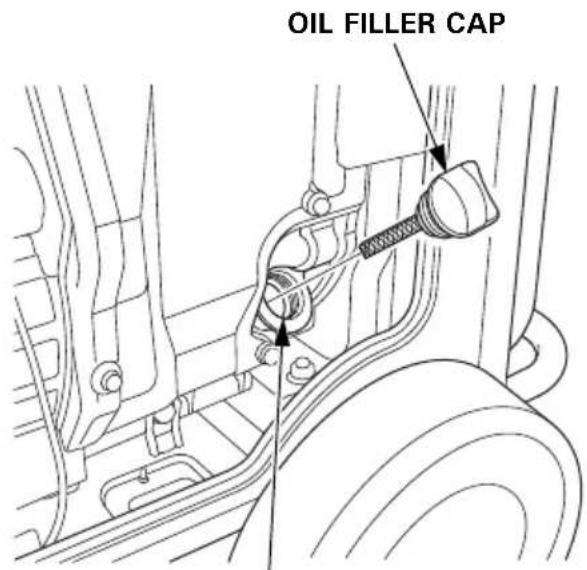
OIL FILLER NECK
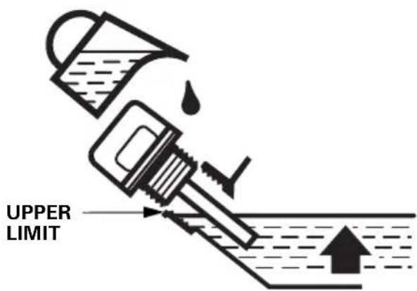
The Oil Alert system will automatically stop the engine before the oil level falls below safe limits. However, to avoid the inconvenience of an unexpected shutdown, check the oil level regularly.
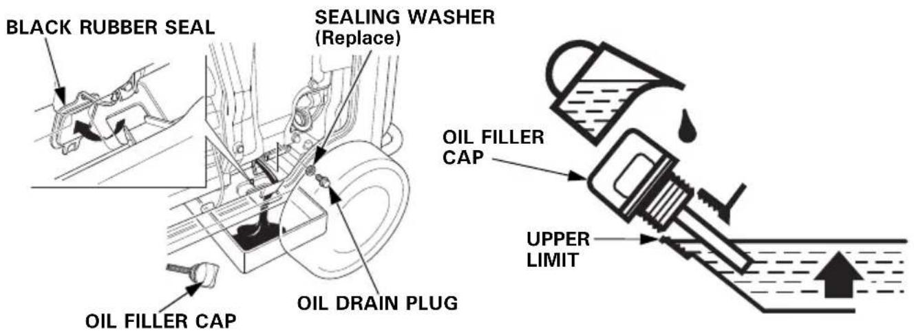
ENGINE OIL CHANGE
Drain the oil while the engine is warm to assure rapid and complete draining.
- Open the right maintenance cover by turning its latch counterclockwise.
- Reach under the generator and remove the black rubber seal located below the oil drain plug.
- Place a suitable container underneath the generator to catch the used oil.
- Remove the oil filler cap.
- Remove the oil drain plug and sealing washer and allow the oil to drain completely.
- Reinstall the oil drain plug and a new sealing washer. Tighten the plug securely.
- Reach under the generator and reinstall the black rubber seal.
NOTICE
Improper disposal of engine oil can be harmful to the environment. If you change your own oil, please dispose of the used oil properly. Put it in a sealed container, and take it to a recycling center. Do not discard it in a trash bin, dump it on the ground, or pour it down the drain.
- With the generator in a level position, fill with the recommended oil (see page 56) to the upper limit of the oil filler neck.
Maximum oil capacity: 1.1 L (1.16 US qt, 0.97 Imp qt)
-
Reinstall the oil filler cap securely.
-
Close the right maintenance cover by turning its latch clockwise.
Wash your hands with soap and water after handling used oil.
ENGINE OIL RECOMMENDATIONS
Oil is a major factor affecting engine performance and service life.
Use 4-stroke motor oil that meets or exceeds the requirements for API service category SE or later (or equivalent). Always check the API SERVICE label on the oil container to be sure it includes the letters SE or later (or equivalent).
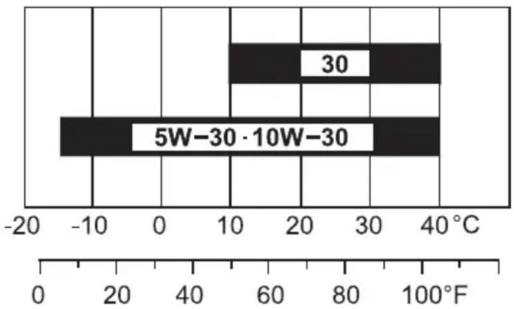
SAE 10W–30 is recommended for general use. Other viscosities shown in the chart may be used when the average temperature in your area is within the recommended range.
Lubrication oil specifications necessary to maintain the performance of the emissions control system: Honda genuine oil.
bar
| Category | Value | |---|---| | 5W-30 | -12 | | 30 | 10 | | 5W-30·10W-30 | 40 |AMBIENT TEMPERATURE
Read the instruction on the oil container before use.
AIR CLEANER SERVICE
-
Open the left maintenance cover by turning its latch counterclockwise.
-
Unsnap the air cleaner cover clips; remove the air cleaner cover.
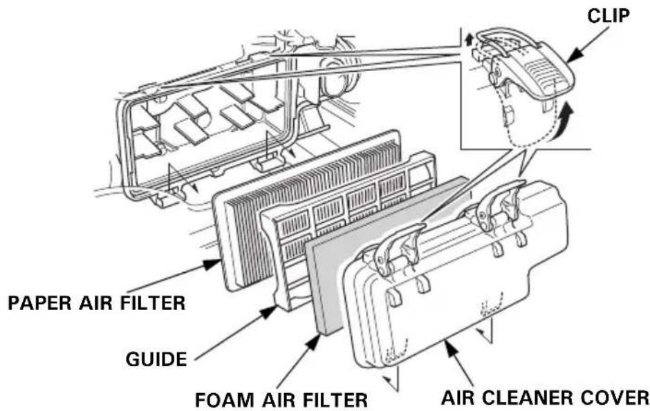
3.Foam air filter:
a. Remove the foam air filter from the air cleaner cover.
b. Check the foam air filter to be sure it is clean and in good condition.
If the foam air filter is dirty, clean it as described on page 58.
Replace the foam air filter if it is damaged.
c. Reinstall the foam air filter in the air cleaner cover.
4.Paper air filter:
a. Remove the guide.
b. If the paper air filter is dirty, replace it with a new one.
Do not clean the paper air filter.
-
Reinstall the guide and the air cleaner cover.
-
Close the left maintenance cover.
NOTICE
Operating the engine without the air filters, or with a damaged air filters, will allow dirt to enter the engine, causing rapid engine wear.
FOAM AIR FILTER CLEANING
A dirty foam air filter will restrict air flow to the fuel system, reducing engine performance. If you operate the generator in very dusty areas, clean the foam air filter more frequently than specified in the Maintenance Schedule.
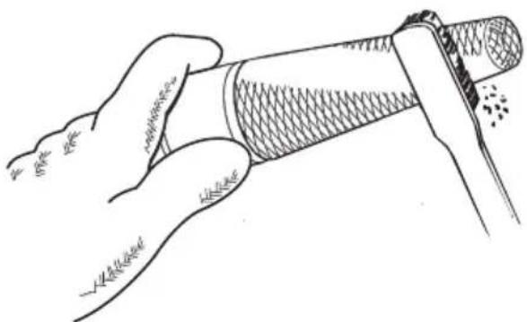
- Clean the foam air filter in warm soapy water, rinse and allow to dry thoroughly, or clean in non-flammable solvent and allow to dry.
- Dip the foam air filter in clean engine oil, and then squeeze out all excess oil. The engine will smoke when started if too much oil is left in the foam air filter.
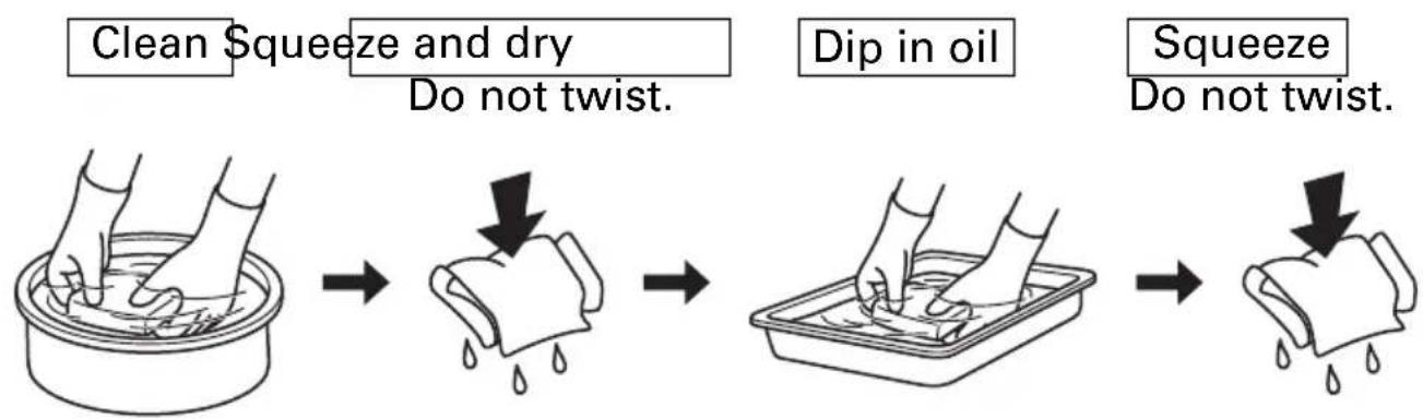
flowchart
graph LR
    A["Clean Squeeze and dry\nDo not twist."] --> B["Dip in oil"]
    B --> C["Squeeze\nDo not twist."]
- Wipe dirt from the inside of the air cleaner cover using a moist rag. Be careful to prevent dirt from entering the air duct that leads to the fuel system.
SPARK PLUG SERVICE
Recommended spark plugs: BPR6ES (NGK)
To ensure proper engine operation, the spark plug must be properly gapped and free of deposits.
NOTICE
An incorrect spark plug can cause engine damage.
If the engine is hot, allow it to cool before servicing the spark plug.
-
Open the left maintenance cover by turning its latch counterclockwise.
-
Loosen the cover screw and remove the spark plug inspection cover.
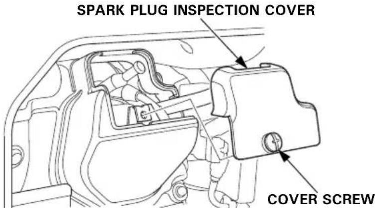
-
Disconnect the spark plug cap, and remove any dirt from around the spark plug area.
-
Remove the spark plug with the spark plug wrench.
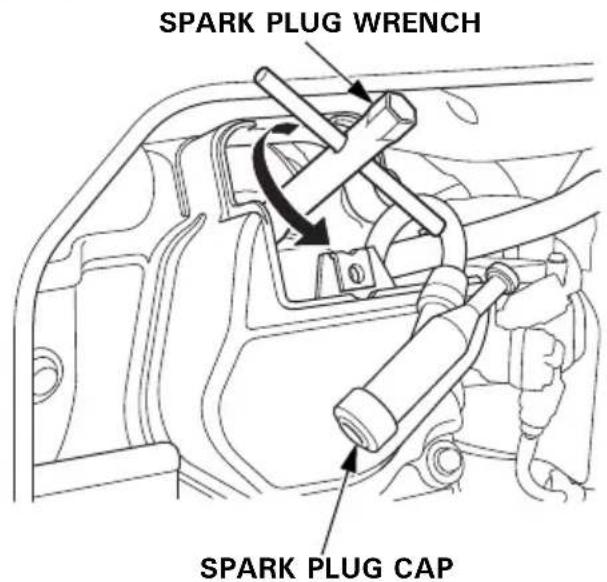
-
Inspect the spark plug. Replace it if the electrodes are worn or fouled, or if the insulator is cracked or chipped.
-
Measure the spark plug electrode gap with a wire-type feeler gauge. Correct the gap, if necessary, by carefully bending the side electrode.
The gap should be: 0.7–0.8 mm (0.028–0.031 in)
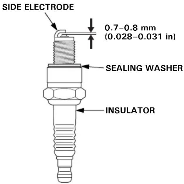
-
Make sure that the spark plug sealing washer is in good condition, and thread the spark plug in by hand to prevent cross-threading.
-
After the spark plug is seated, tighten with the spark plug wrench to compress the washer.
If reinstalling a used spark plug, tighten 1/8–1/4 turn after the spark plug seats.
If installing a new spark plug, tighten 1/2 turn after the spark plug seats.
NOTICE
A loose spark plug can overheat and damage the engine. Overtightening the spark plug can damage the threads in the cylinder head.
-
Attach the spark plug cap.
-
Reinstall the spark plug inspection cover and tighten the cover screw.
-
Close the left maintenance cover.
SPARK ARRESTER SERVICE
If the engine has been running, the muffler will be very hot. Allow the muffler to cool before servicing the spark arrester.
- Remove the two 5 × 16 mm pan head screws, and remove the tail pipe and spark arrester.
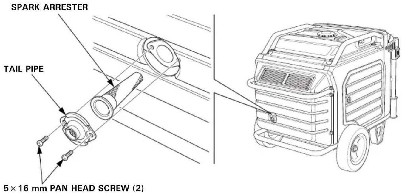
- Use a brush to remove carbon deposits from the spark arrester screen.
Be careful to avoid damaging the screen.
The spark arrester must be free of breaks and tears. Replace the spark arrester if it is damaged.
natural_image
Illustration of a hand holding a cylindrical object with textured surface (no text or symbols)- Install the spark arrester in the reverse order of removal.
BATTERY SERVICE
Your generator's engine charging system charges the battery while the engine is running. However, if the generator is only used periodically, the battery must be charged monthly to maintain the battery service life.
WARNING
The battery contains sulfuric acid (electrolyte), which is highly corrosive and poisonous.
Getting electrolyte in your eyes or on your skin can cause serious burns.
Wear protective clothing and eye protection when working near the battery.
KEEP CHILDREN AWAY FROM THE BATTERY.
Emergency Procedures
Eyes – Flush with water from a cup or other container for at least fifteen minutes. (Water under pressure can damage the eye.) Call a physician immediately.
Skin – Remove contaminated clothing. Flush the skin with large quantities of water. Call a physician immediately.
Swallowing – Drink water or milk. Call a physician immediately.
Battery Removal
Battery posts, terminals, and related accessories contain lead and lead compounds. Wash hands after handling.
- Lift the handle upward. The lock levers will lock and secure the handle in place.
- Loosen the cover screw and remove the battery maintenance cover.
-
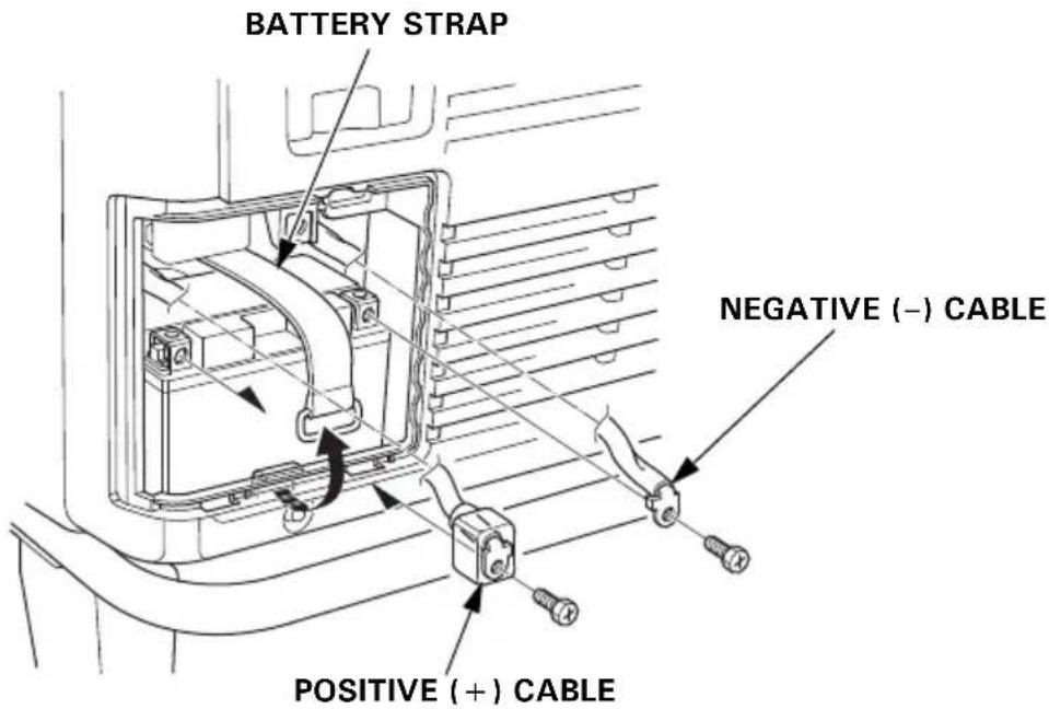
Remove the negative (−) cable from the battery negative (−) terminal, and then remove the positive (+) cable from the battery positive (+) terminal.
-
Unhook the battery strap from the bottom hook of the generator.
- Remove the battery.
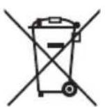
This symbol on the battery means that this product must not be treated as household waste.
An improperly disposed of battery can be harmful to the environment and human health.
Always confirm local regulations for battery disposal.
Battery Charging
WARNING
The battery gives off explosive hydrogen gas during normal operation.
A spark or flame can cause the battery to explode with enough force to kill or seriously hurt you.
Wear protective clothing and a face shield, or have a skilled mechanic perform the battery maintenance.
The battery is rated at 11.2 Ah (ampere-hours). Charging current should equal 10% of the battery's ampere-hour rating. A battery charger should be used that can be adjusted to deliver 1.1 amps.
- Connect the battery charger following the manufacturer's instructions.
- Charge the battery 5–10 hours.
- Clean the outside of the battery and the battery compartment with a solution of baking soda and water.
Battery Installation
- Install the battery into the generator.
- Connect the positive (+) cable to the battery positive (+) terminal first, and tighten the bolt securely.
3.Slide the battery boot over the positive (+) cable and terminal. - Connect the negative (−) cable to the battery negative (−) terminal, and tighten the bolt securely.
- Install the battery strap.
- Install the battery maintenance cover in the reverse order of removal (see page 63).
Never operate the generator with the battery maintenance cover open, as poor engine and generator performance will result.
FUSE
If the fuse is blown, the starter motor will not operate.
In the event of fuse failure, locate the cause of failure and repair it before you continue operation. If the fuse continues to fail, discontinue generator use and consult your servicing dealer.
-
Turn the MAIN switch to the OFF position and remove the key before checking or replacing the fuse.
-
Loosen the cover screw and remove the battery maintenance cover.
-
Remove the fuse holder cover and pull the fuse out.
-
Replace the fuse with a fuse of the same type and rating.
Specified fuse: 3 A, 15 A
NOTICE
Never use a fuse with a different rating from that specified. Serious damage to the electrical system or fire may result.
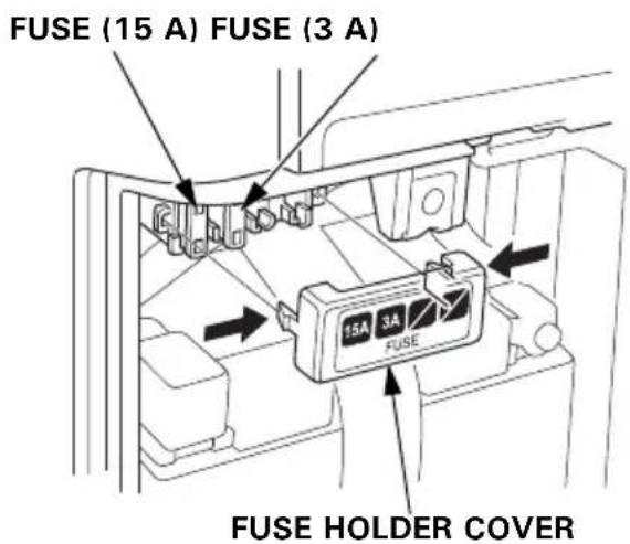
- Install the fuse holder cover and the battery maintenance cover in the reverse order of removal (see page 63).
Never operate the generator with the battery maintenance cover open, as poor engine and generator performance will result.
STORAGE
STORAGE PREPARATION
Proper storage preparation is essential for keeping your generator trouble-free and looking good. The following steps will help to keep rust and corrosion from impairing your generator's function and appearance, and will make the engine easier to start when you use the generator again.
Cleaning
Wipe the generator with a moist cloth. After the generator has dried, touch up any damaged paint, and coat other areas that may rust with a light film of oil.
Fuel
NOTICE
Depending on the region where you operate your equipment, fuel formulations may deteriorate and oxidize rapidly. Fuel deterioration and oxidation can occur in as little as 30 days and may cause damage to the fuel system. Please check with your servicing dealer for local storage recommendations.
Gasoline will oxidize and deteriorate in storage. Old gasoline will cause hard starting, and it leaves gum deposits that clog the fuel system. If the gasoline in your generator deteriorates during storage, you may need to have the fuel system components serviced or replaced.
The length of time that gasoline can be left in your fuel tank without causing functional problems will vary with such factors as gasoline blend, your storage temperatures, and whether the fuel tank is partially or completely filled. The air in a partially filled fuel tank promotes fuel deterioration. Very warm storage temperatures accelerate fuel deterioration. Fuel deterioration problems may occur within a few months, or even less if the gasoline was not fresh when you filled the fuel tank.
Draining the Fuel Tank
WARNING
Gasoline is highly flammable and explosive.
You can be burned or seriously injured when handling fuel.
- Stop the engine and let it cool before handling fuel.
- Keep heat, sparks and flame away.
- Handle fuel only outdoors.
- Keep away from your vehicle.
- Wipe up spills immediately.
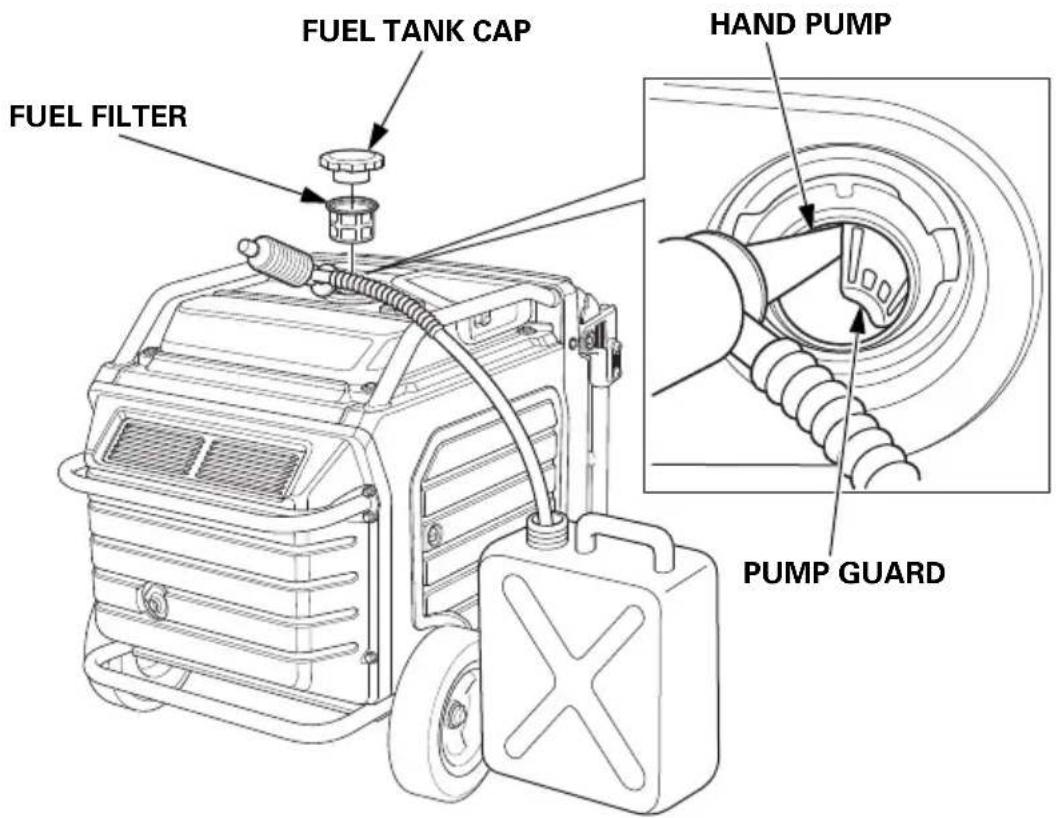
Unscrew the fuel tank cap, remove the fuel filter, and empty the fuel tank into an approved gasoline container. We recommend using a commercially available gasoline hand pump to empty the tank. Do not use an electric pump. Siphon the gasoline by inserting the tip of the hand pump into the side of the pump guard. Reinstall the fuel filter and the fuel tank cap.
Engine Oil
- Change the engine oil (see page 55).
- Remove the spark plug (see page 59).
- Pour a teaspoon (5 cm ^4 ) of clean engine oil into the cylinder.
- Pull the starter rope several times to distribute the oil in the cylinder.
- Reinstall the spark plug (see page 60).
- Slowly pull the starter grip until resistance is felt. At this point, the piston is coming up on its compression stroke and both the intake and exhaust valves are closed. Storing the engine in this position will help to protect it from internal corrosion. Return the starter grip gently.
Battery
Charge the battery before storing the generator (see page 65).
STORAGE PRECAUTIONS
If your generator will be stored with gasoline in the fuel tank, it is important to reduce the hazard of gasoline vapor ignition.
Select a well ventilated storage area away from any appliance that operates with a flame, such as a furnace, water heater, or clothes dryer. Also avoid any area with a spark-producing electric motor, or where power tools are operated.
If possible, avoid storage areas with high humidity, because that promotes rust and corrosion.
Place the generator on a level surface. Tilting can cause fuel or oil leakage.
With the engine and exhaust system cool, cover the generator to keep out dust. A hot engine and exhaust system can ignite or melt some materials.
Do not use a plastic sheet as a dust cover. A nonporous cover will trap moisture around the generator, promoting rust and corrosion.
Fully charge the battery. Recharge the battery once a month (see page 65).
REMOVAL FROM STORAGE
Check your generator as described in the BEFORE OPERATION chapter of this manual (see page 29).
If the generator was stored for 1 year or longer, drain the fuel tank (see page 68) and refuel with fresh gasoline. If you keep a container of gasoline for refueling, be sure that it contains only fresh gasoline. Gasoline oxidizes and deteriorates over time, causing hard starting.
If the cylinder was coated with oil during storage preparation, the engine may smoke briefly at startup. This is normal.
TRANSPORTING
If the generator has been running, allow the engine to cool for at least 15 minutes before loading the generator on the transport vehicle. A hot engine and exhaust system can burn you and can ignite some materials.
Keep the generator level when transporting to reduce the possibility of fuel leakage.
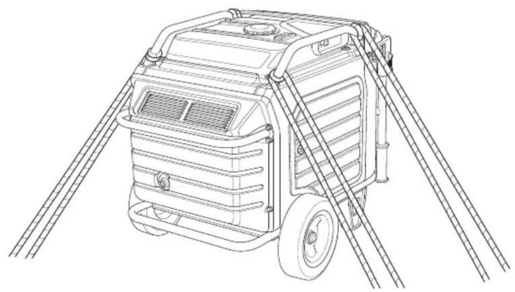
When using ropes or tie-down straps to secure the generator for transportation, be sure to only use the frame bars as attachment points. Do not fasten ropes or straps to any portions of the generator body or the folding handle.
When transporting the generator:
- Do not overfill the tank.
- Do not operate the generator while it is on a vehicle. Take the generator off the vehicle and use it in a well ventilated place.
- Avoid a place exposed to direct sunlight when putting the generator on a vehicle. If the generator is left in an enclosed vehicle for many hours, high temperature inside the vehicle could cause fuel to vaporize resulting in a possible explosion.
- Do not drive on a rough road for an extended period with the generator on board. If you must transport the generator on a rough road, drain the fuel from the generator beforehand.
natural_image
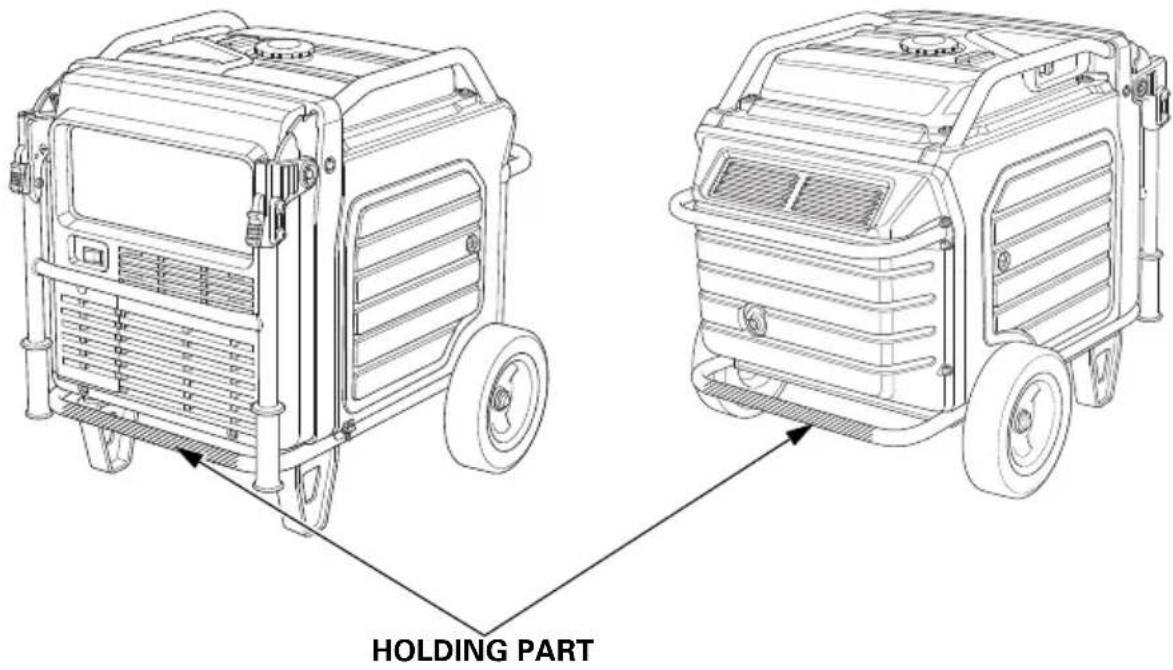
Line drawing of a portable gas generator with attached ladder and roof structure (no text or symbols)- Use a hoist and attach it on the hanger (optional parts) of your generator to lift it up for transportation.
- When you are to lift up your generator with your assistants by hands, take care not to lift it up by holding the handle or rear bar of the generator. Be sure to lift up the generator by holding the holding part (shaded areas in the figure below).
According to EUROPEAN STANDARD EN ISO 8528-13
Carrying the generating set is considered that a 140 kg set should be provided with the means of carrying by 4 persons.
TAKING CARE OF UNEXPECTED PROBLEMS
ENGINE WILL NOT START
| Possible Cause Correction | |
| MAIN switch is in the OFF position. | Turn MAIN switch to ON position (see page 34). |
| Out of fuel. Refuel (see page 52). | |
| Bad fuel, generator stored without draining gasoline, or refueled with bad gasoline. | Drain fuel tank (see page 68). Refuel with fresh gasoline (see page 52). |
| Low engine oil level caused Oil Alert to stop engine. | Turn MAIN switch to OFF position. Add engine oil. Then turn MAIN switch to ON position and restart the engine. |
| Spark plug wet with fuel (flooded engine). | • Turn MAIN switch to OFF position and pull starter grip swiftly five times or more. This may dry spark plug.• If it still not start, remove spark plug and dry. |
| Spark plug faulty, fouled, or improperly gapped. | Gap or replace spark plug (see page 59). Reinstall spark plug. |
| Fuel filter restricted, fuel system malfunction, fuel pump failure, ignition malfunction, valves stuck, etc. | Take the generator to your servicing dealer, or refer to the shop manual. |
ENGINE LACKS POWER
| Possible Cause Correction | |
| Air filter restricted. Clean or replace air filter (see page 57). | |
| Bad fuel, generator stored without draining gasoline, or refueled with bad gasoline. | Drain fuel tank (see page 68). Refuel with fresh gasoline (see page 52). |
| Fuel filter restricted, fuel system malfunction, fuel pump failure, ignition malfunction, valves stuck, etc. | Take the generator to your servicing dealer, or refer to the shop manual. |
NO POWER AT THE AC RECEPTACLES
| Possible Cause Correction | |
| OUTPUT indicator is OFF, and OVERLOAD ALARM indicator is ON. | Check AC load. Stop and restart the engine. |
| Check the cooling air inlet. Stop and restart the engine. | |
| AC Circuit protector(s) tripped. Check AC load and reset AC circuit protector(s) (see page 18). | |
| Faulty power tool or appliance. Replace or repair power tool or appliance. Stop and restart the engine. | |
| Faulty generator. Take the generator to your servicing dealer, or refer to the shop manual. | |
TECHNICAL INFORMATION
Serial Number Location
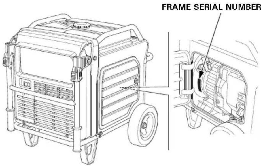
Record the frame serial number and date purchased in the spaces below. You will need this information when ordering parts and when making technical or warranty inquiries.
Frame serial number:
Date purchased:
Specifications
Dimensions
| Model | EU70isN |
| Description code EEJD | |
| Length[Handle in up position] | 848 mm (33.4 in)[1,198 mm (47.2 in)] |
| Width 700 mm (27.6 in) | |
| Height 721 mm (28.4 in) | |
| Dry mass [weight]* | 118.1 kg (260.4 lbs) |
* With battery
Engine
| Model GX390T2 | |
| Engine type 4-stroke, overhead | valve, single cylinder |
| Displacement[BorexStroke] | 389 cm^3 (23.7 cu-in) [88 × 64 mm (3.5 × 2.5 in)] |
| Compression ratio 8.2:1 | |
| Engine speed 2,400–3,600 rpm | |
| Cooling system Forced air | |
| Ignition system Full transistor ignition | |
| Engine oil capacity 1.1 L (1.16 US qt, 0.97 Imp qt) | |
| Fuel tank capacity 19.2 L (5.07 US gal, 4.22 Imp gal) | |
| Spark plug BPR6ES (NGK) | |
| Battery | 12 V 11.2 Ah/10 HR |
[Carbon dioxide (CO2) emissions ^* ]
Please refer to "CO2 Information List" on
www.honda-engines-eu.com/co2
* The CO2 measurement results from testing over a fixed test cycle under laboratory conditions a(n) (parent) engine representative of the engine type (engine family) and shall not imply or express any guarantee of the performance of a particular engine.
Generator
| Model | EU70isN | |
| Type | GWT, FT, ITT | |
| AC output | Rated voltage | 230 V |
| Rated frequency | 50 Hz | |
| Rated current (Rated ampere) | 23.9 A | |
| Rated output | 5.5 kVA | |
| Maximum output | 7.0 kVA | |
Noise
| Model EU70isN | |
| Type GWT, FT, ITT | |
| Sound pressure level at the workstation(2006/42/EC) | 76 dB (A)(with Eco throttle ON) |
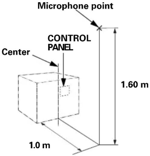 | |
| Uncertainty 2 dB (A) | |
| Measured sound power level(2000/14/EC, 2005/88/EC) | 88 dB (A)(with Eco throttle ON) |
| Uncertainty 2 dB (A) | |
| Guaranteed sound power level(2000/14/EC, 2005/88/EC) | 90 dB (A)(with Eco throttle ON) |
“the figures quoted are emission levels and are not necessarily safe working levels. Whilst there is a correlation between the emission and exposure levels, this cannot be used reliably to determine whether or not further precautions are required. Factors that influence the actual level of exposure of work-force include the characteristics of the work room, the other sources of noise, etc. i.e. the number of machines and other adjacent processes, and the length of time for which an operator is exposed to the noise. Also the permissible exposure level can vary from country. This information, however, will enable the user of the machine to make a better evaluation of the hazard and risk”.
Specifications may vary according to the types, and are subject to change without notice.
Wiring Diagram
(See inside back cover)
Abbreviations
| Symbol | Part name |
| ACCP | AC Circuit Protector |
| ACOR | AC Output Receptacle |
| Bat | Battery |
| CPB | Control Panel Block |
| CSw | Combination Switch |
| EcoSw | Eco Throttle Switch |
| EgB | Engine Block |
| FrB | Frame Block |
| FP | Fuel Pump |
| FuB | Fuse Box |
| GeB | Generator Block |
| GCU | Generator Control Unit |
| GND | Ground |
| GT | Ground Terminal |
| IgC | Ignition Coil |
| IgPG | Ignition Pulse Generator |
| In | Injector |
| IU | Inverter Unit |
| IUB | Inverter Unit Block |
| LED | LED |
| MSw | MAIN Switch |
| MW | Main Winding |
| NF | Noise Filter |
| OLSw | Oil Level Switch |
| O2Se | O2 Sensor |
| PC | Personal Computer |
| POR | Parallel Operation |
| Receptacle | |
| Rc | Remote Control |
| RCB | Remote Control Block |
| Rc (OP) | Remote Control (Option) |
| SP | Spark Plug |
| StM | Starter Motor |
| StSw | Start Switch |
| SW | Slave Winding |
| TCM | Throttle Control Motor |
| ThSe | Thermo Sensor |
Wire color code
| BI | Black |
| Br | Brown |
| G | Green |
| Gr | Gray |
| Bu | Blue |
| Lb | Light blue |
| Lg | Light green |
| O | Orange |
| P | Pink |
| R | Red |
| W | White |
| Y | Yellow |
| V | Violet |
| BE | Beige |
CONBINATION SWITCH
The Importance of Proper Assembly
Proper assembly is essential to operator safety and the reliability of the machine. Any error or oversight made by the person assembling and servicing a unit can easily result in faulty operation, damage to the machine, or injury to the operator.
WARNING
Improper assembly can cause an unsafe condition that can lead to serious injury or death.
Follow the procedures and precautions in the assembly instructions carefully.
Some of the most important safety precautions are given below. However, we cannot warn you of every conceivable hazard that can arise in performing this assembly. Only you can decide whether or not you should perform a given task.
WARNING
Failure to properly follow instructions and precautions can cause you to be seriously hurt or killed.
Follow the procedures and precautions in this manual carefully.
Important Safety Precautions
- Make sure you have a clear understanding of all basic shop safety practices and that you are wearing appropriate clothing and safety equipment. When performing this assembly, be especially careful of the following:
☐ Read the instructions before you begin, and be sure you have the tools and skills required to perform the tasks safely.
- Make sure the engine is off before you begin any assembly, maintenance, or repairs. This will help eliminate several potential hazards:
☐ Carbon monoxide poisoning from engine exhaust. Operate outside away from open windows or doors.
☐ Burns from hot parts. Let the engine and exhaust system cool before touching.
☐ Injury from moving parts. Do not run the engine unless the instruction tells you to do so. Even then, keep your hands, fingers, and clothing away. Do not run the engine when any protective guard or shield is removed.
- To reduce the possibility of a fire or explosion, be careful when working around gasoline or batteries. Use only a non-flammable solvent, not gasoline, to clean parts. Keep all cigarettes, sparks, and flames away from all fuel-related parts.
ASSEMBLY
Unpacking
-
Remove the generator and loose parts box from the carton.
-
Compare the loose parts with the inventory list below.
Tools Required: 12 mm wrench, 10 mm wrench or Phillips head screwdriver for battery connections, pliers (not included)
Loose Parts
Check all loose parts against the following list.
| Ref. No. | Description Qty. | |
| 1 Wheel 2 | ||
| 2 Axle 1 | ||
| 3 Stand 2 | ||
| 4 20 mm Washer 2 | ||
| 5 4.0 × 28 mmCotter pin | 2 | |
| 6 8 × 20 mmFlange bolt | 8 | |
(1)
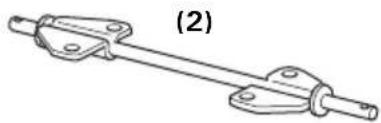
natural_image
Mechanical linkage component diagram with labeled part (2), no text or symbols present
(3)
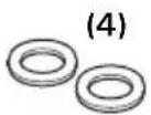
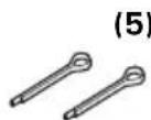

Wheel Kit Installation
Do not operate the generator without the wheel kit installed. The wheel kit provides air space between the ground and the generator air intake.
NOTICE
If the wheel kit is not installed, it may be possible for dirt and debris to be drawn into the generator air intake, possibly causing generator damage. Always operate the generator with the wheel kit installed.
- Install the two wheels on the axle using the 20 mm washers and 4.0 × 28 mm cotter pins.
- Install the axle assembly on the generator using four 8 × 20 mm flange bolts.
- Install the two stands on the under frame using four 8 × 20 mm flange bolts.
TORQUE: 15–22 N·m (1.5–2.2 kgf·m, 11–16 lbf·ft)
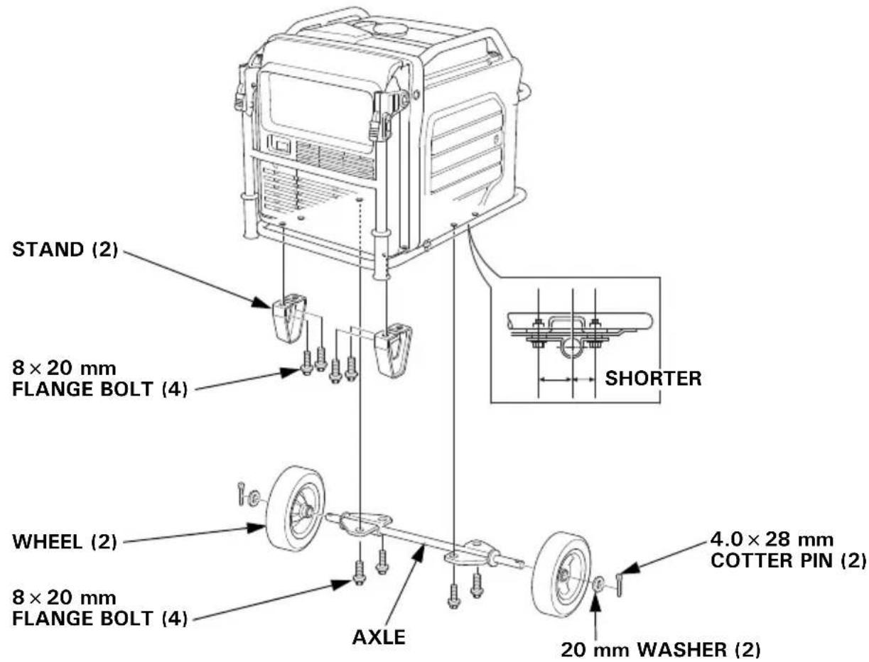
Battery
Battery posts, terminals, and related accessories contain lead and lead compounds. Wash hands after handling.
The battery is disconnected and strapped into the battery tray for shipment.
- Remove the battery maintenance cover (see page 63).
- Remove the battery strap from the bottom hook, and then remove the battery.
- Only remove the battery cables from the twist clip.
Make sure that the 4-pin blue coupler harness is secured with the twist clip.
Charge the battery properly. See page 65.
Reinstall the battery.
-
Remove the protective cover from the battery positive (+) terminal, and connect the positive (+) cable to the battery positive (+) terminal. Make sure to cover the terminal with the battery boot.
-
Connect the negative (−) cable to the battery negative (−) terminal.
-
Secure the battery by hooking the strap onto the bottom hook of the generator.
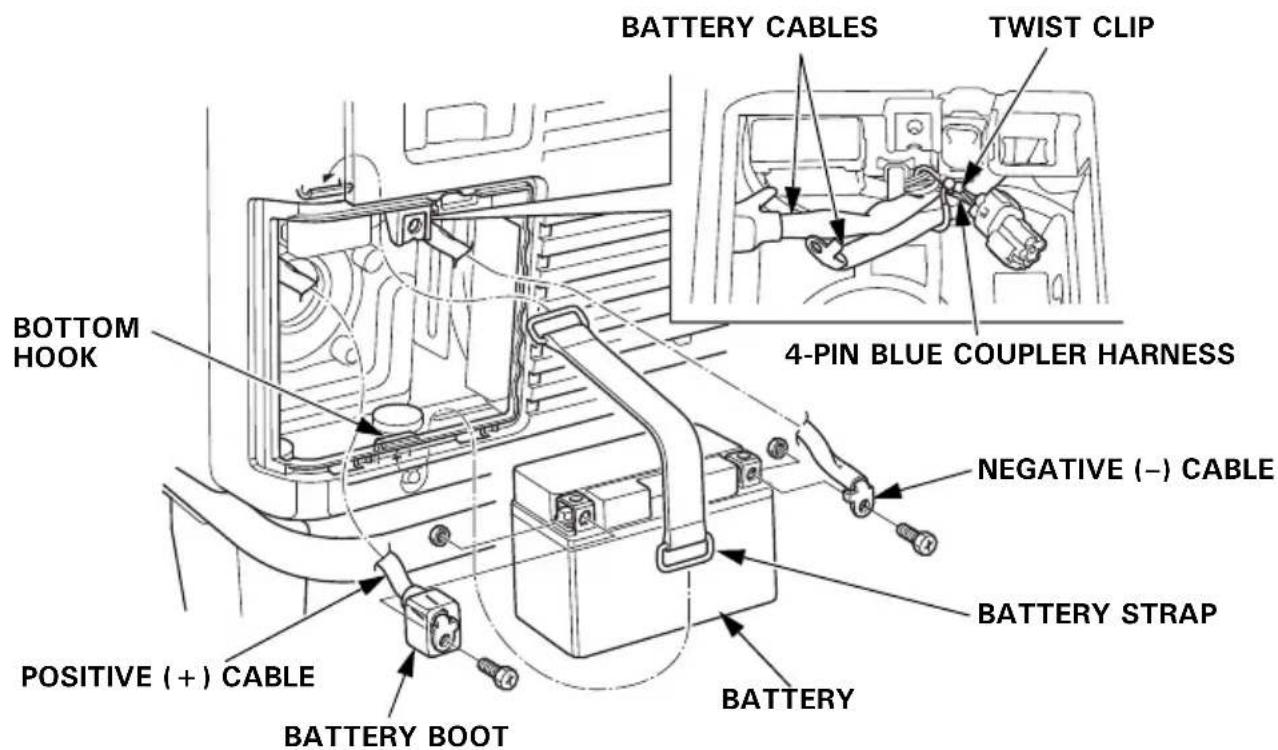
- Install the battery maintenance cover in the reverse order of removal (see page 63).
Never operate the generator with the battery maintenance cover open, as poor engine and generator performance will result.
Engine Oil
The generator is shipped WITHOUT OIL in the engine.
Place the generator on a level surface. Open the right maintenance cover by turning its latch counterclockwise. Remove the oil filler cap. Add enough of the recommended oil to bring the oil level to the upper limit of the oil filler neck.
Use a 4-stroke motor oil that meets the requirements for API service category SE or later (or equivalent).
SAE 10W-30 is recommended for general, all-temperature use. Other viscosities in the chart may be used when the temperature in your area is within the indicated range. Lubrication oil specifications necessary to maintain the performance of the emissions control system: Honda genuine oil.
Reinstall the oil filler cap securely.
Close the right maintenance cover by turning its latch clockwise.
Fuel
Refer to page 52.
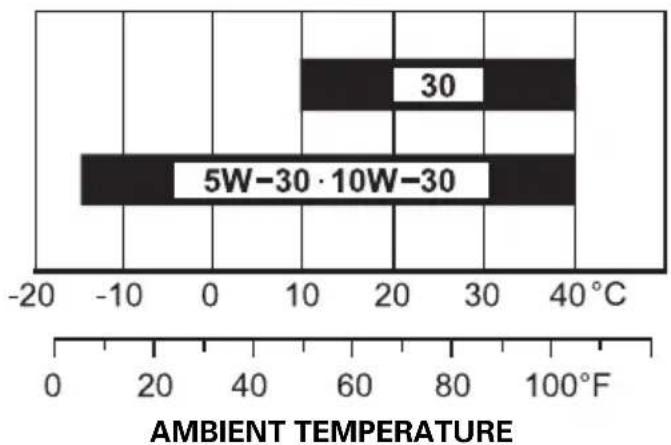
bar
| Temperature Range | Value | | :--- | :--- | | 30 | 10 | | 5W-30·10W-30 | -10 |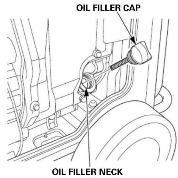
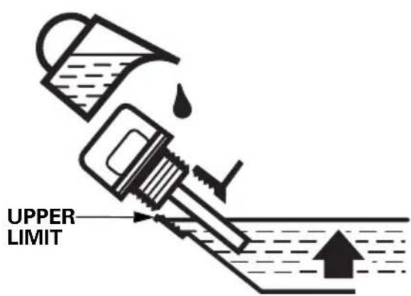
Battery Voltage
Check the battery voltage with the i-Monitor (see page 26).
The battery voltage should be 12.3 V or more.
If the battery voltage is low, charge the battery until the battery voltage is 12.3 V or more.
BEFORE OPERATION
Before using the generator, all generator operators must read the following chapters and sections:
- GENERATOR SAFETY (page 6)
• CONTROLS & FEATURES (see page 14) - BEFORE OPERATION (see page 29)
• OPERATION (see page 31)
• STARTING THE ENGINE (see page 33)
• STOPPING THE ENGINE (see page 36) - MAINTENANCE SCHEDULE (see page 51)
OPTIONAL PARTS
REMOTE CONTROL KIT
Using the remote control in wet conditions, such as rain or snow, or near a pool or sprinkler system, or when your hands are wet, could result in malfunction. Keep the remote control dry.
(degree of protection: IP3X)
-
Remove the battery maintenance cover (see page 63).
-
Remove the plug from the connector.
- Do not discard the plug. The plug should be installed back into the connector when the remote control kit is removed.
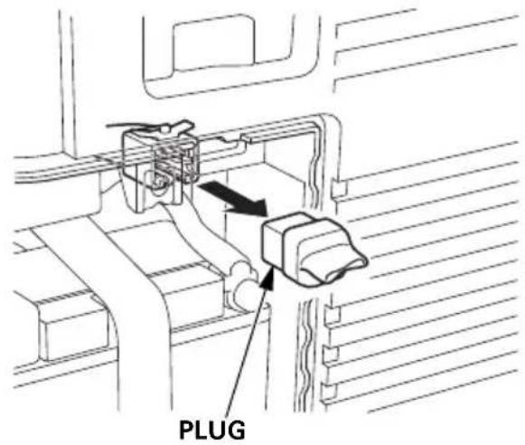
3.View the back of the battery maintenance cover and locate the knockout near the top center of the cover. Carefully remove the knockout.
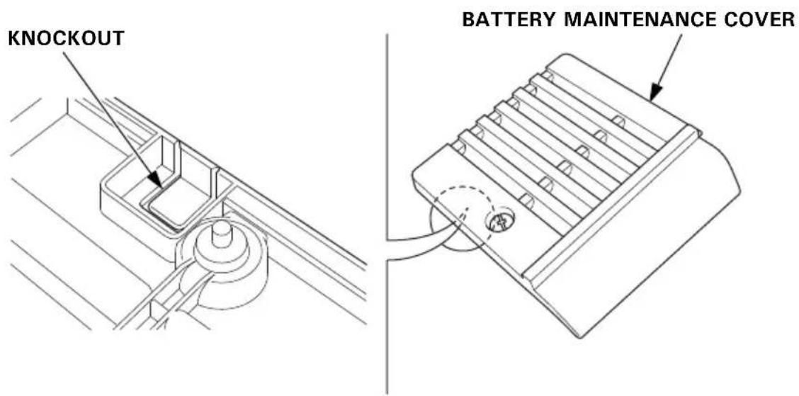
- Fit the grommet into the battery maintenance cover knockout.
- Plug the remote control cable into the connector.
- Install the battery maintenance cover and tighten the cover screw.
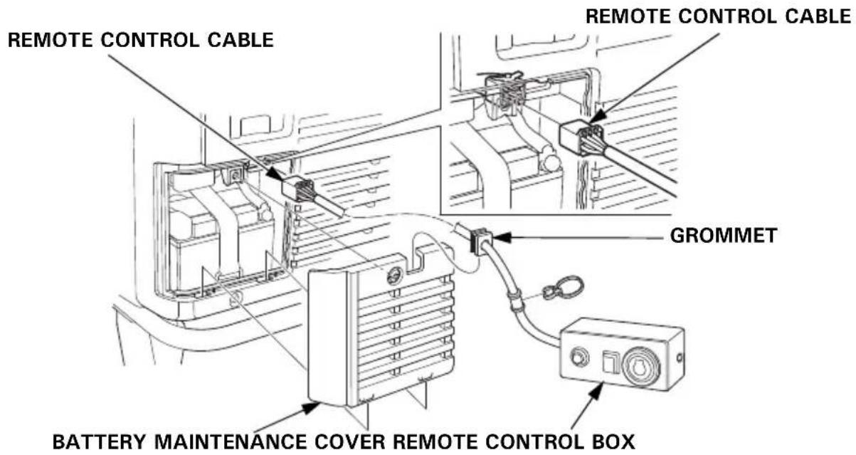
- To avoid accidentally unplugging the remote control cable, secure the cable to the generator frame with a cable tie as shown.
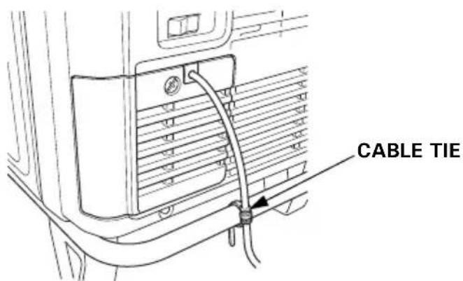
- Never operate the generator with the battery maintenance cover open, as poor engine and generator performance will result.
• Install the plug to the connector when the remote control kit is removed.
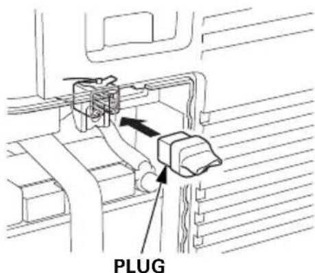
HANGER KIT
Protect the fuel tank and frame pipe with the protector films during installation of the hanger.
- Slide one end of the hanger under the frame pipe on the left side of the generator.
- Slide the other end of the hanger under the frame pipe on the right side of the generator.
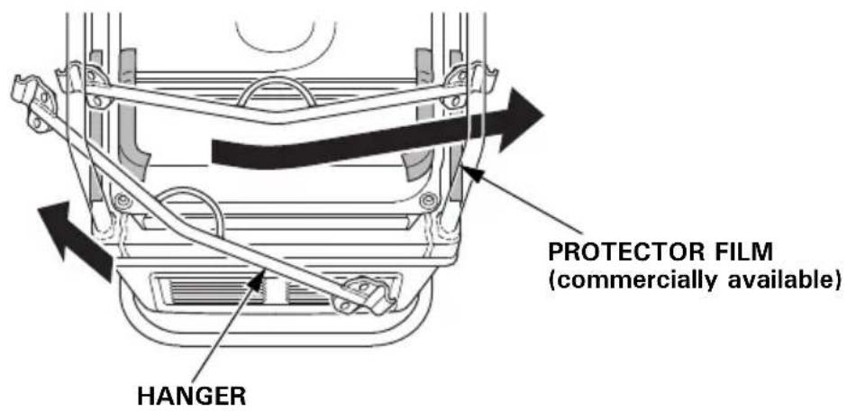
- Slide the hanger along the frame pipes to align the center of the hanger with the recessed part on the rear side of the fuel tank.
- Install the hanger brackets on both ends of the hanger and tighten the 8 × 16 mm flange bolts securely.
TORQUE: 24–29 N·m (2.4–3.0 kgf·m, 17–22 lbf·ft)
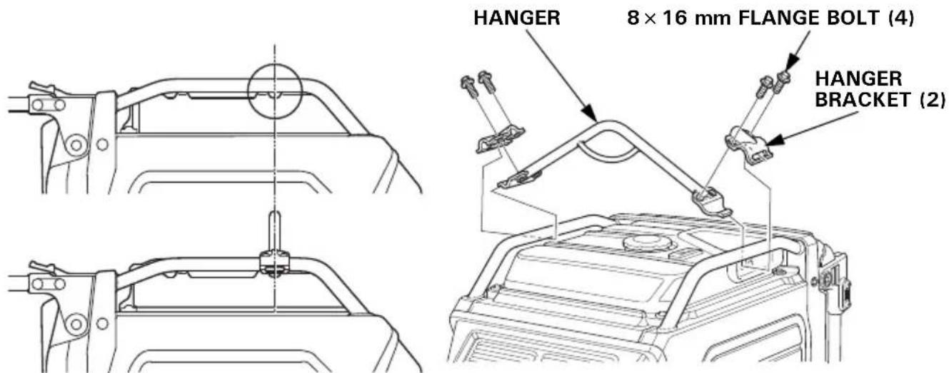
MEMO
Honda EU70is
MANUEL DE L'UTILISATEUR
Notice originale
ATTENTION
RECOMMANDATIONS POUR LE CARBURANT 53
CONTROLE DU NIVEAU D'HUILE MOTEUR.... 54
VIDANGE DE L'HUILE MOTEUR ....55
RECOMMANDATIONS POUR L'HUILE MOTEUR 56
ENTRETIEN DU FILTRE A AIR 57
NETTOYAGE DU FILTRE A AIR EN MOUSSE.... 58
ENTRETIEN DE LA BOUGIE D'ALLUMAGE 59
ENTRETIEN DU PARE-ETINCELLES 61
ENTRETIEN DE LA BATTERIE.... 62
FUSIBLE.... 66
REMISAGE 67
PREPARATION AU REMISAGE 67
Nettoyage 67
Carburant.... 67
Huile moteur.... 69
Batterie.... 69
PRECAUTIONS DE REMISAGE 70
FIN DU REMISAGE 70
TRANSPORT ....71
EN CAS DE PROBLEME INATTENDU ....73
LE MOTEUR NE DEMARRE PAS ....73
LE MOTEUR MANQUE DE PUISSANCE 74
PAS DE COURANT AUX PRISES CA 74
INFORMATIONS TECHNIQUES....75
natural_image
Line drawing of a computer control panel with buttons and an antenna (no text or symbols)natural_image
Diagram of a mechanical component with directional arrows indicating motion or force (no text or symbols)LOQUET
natural_image
Line drawing of a wall-mounted electrical outlet with three buttons and a pointer (no text or symbols)Témoin OIL ALERT/VERIFICATION D'HUILE
i-Monitor
natural_image
Line drawing of a portable gas generator with wheels and ventilation slots (no text or symbols)RECOMMANDATIONS POUR LE CARBURANT
bar
| Category | Value | |---|---| | 5W-30·10W-30 | -15 | | 30 | 12 | | 40°C (top) | 40 | The chart displays a single bar for the 5W-30·10W-30 range. The values for the 30 bar are explicitly labeled as 30.TEMPERATURE AMBIANTE
natural_image
Illustration of a hand holding a cylindrical object with textured surface (no text or symbols)natural_image
Line drawing of a portable gas generator with attached pipes and wheels (no text or symbols)PAS DE COURANT AUX PRISES CA
natural_image
Mechanical linkage component diagram with labeled part (2), no text or symbols present
(3)


bar
| Category | Value | |---|---| | 5W-30·10W-30 | -15 | | 30 | 12 | | Other (Left) | 30 | | Other (Right) | 30 |TEMPERATURE AMBIANTE
BOUCHON DE REMPLISSAGE D'HUILE
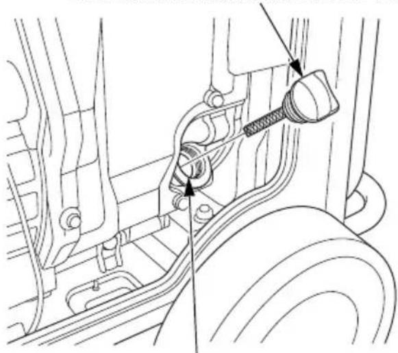
natural_image
Technical line drawing of a mechanical assembly with no visible text or symbolsGOULOT DE REMPLISSAGE D'HUILE
KIT D'ANSE DE SUSPENSION
natural_image
Line drawing of a device panel with three buttons and a pointer (no text or symbols)natural_image
Illustration of a hand holding a cylindrical object with textured surface (no text or symbols)Motoröl
natural_image
Line drawing of a portable electricity generator with coiled cables attached (no text or symbols)natural_image
Mechanical linkage component diagram with labeled part (2), no text or symbols present
(3)
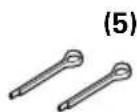
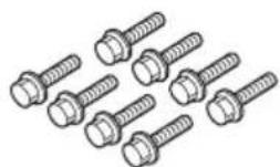
Einbau Radsatz
Batteriespannung
ANZUGSDREHMOMENT: 24–29 N·m (2,4–3,0 kgf·m)
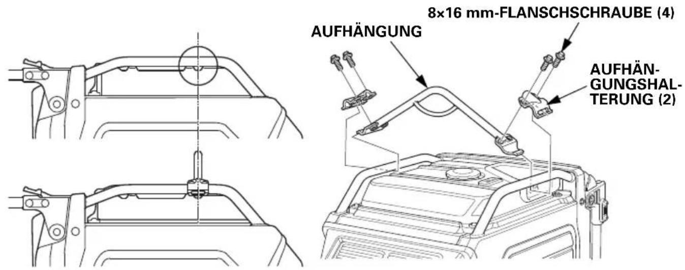
natural_image
Line drawing of a wall-mounted electrical outlet with three buttons and a pointer (no text or symbols)SPIA DI USCITA (VERDE)
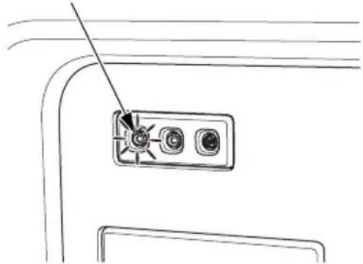
natural_image
Line drawing of a device panel with three buttons and a pointer (no text or symbols)Candele raccomandate: BPR6ES (NGK)
natural_image
Illustration of a hand holding a cylindrical object with textured surface (no text or symbols)natural_image
Line drawing of a portable gas generator with ladder and support structure (no text or symbols)TRATTAMENTO DEI PROBLEMI IMPREVISTI
IL MOTORE NON SI AVVIA
natural_image
Mechanical linkage component diagram with labeled part (2), no text or symbols present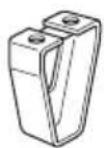
(3)

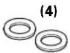
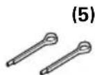
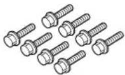
natural_image
Technical line drawing of a mechanical assembly with no visible text or symbolsCOPPIA DI SERRAGGIO: 24–29 N·m (2,4–3,0 kgf·m)
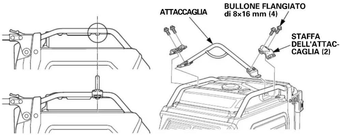
For further information, please contact Honda Customer Information Centre at the following address or telephone number:
ADRESSES DES PRINCIPAUX DISTRIBUTEURS Honda
BALTIC STATES (Estonia/Latvia/ Lithuania)
NCG Import Baltics OU
Meistri 12
Haabersti District
13517 Tallinn
Harju County Estonia
Tel.: +372 651 7300
Fax: +372 651 7301

info.baltic@ncgimport.com
BELARUS
UAB JP Motors
Montazhnikov lane 4th, 5-16
Minsk 220019
Republic of Belarus
Tel.: +375172349999
Fax: +375172380404

Dudarevich@scanlink.by
BELGIUM
Honda Motor Europe Ltd
Doornveld 180-184
1731 Zellik
Tel.: +32 2620 10 00
Fax: +32 2620 10 01
http://www.honda.be

BH_PE@HONDA-EU.COM
BULGARIA
Premium Motor Ltd
Andrey Lyapchev Blvd no 34
1797 Sofia
Bulgaria
Tel.: +3592 423 5879
Fax: +3592 423 5879
http://www.hondamotor.bg

office@hondamotor.bg
CROATIA
Hongoldonia d.o.o.
Vukovarska ulica 432a
31000 Osijek, HR
Tel.: +38531320420
Fax: +38531320429
http://www.hongoldonia.hr

prodaja@hongoldonia.hr
CROATIA
Fred Bobek d.o.o.
HONDA MARINE
Put Gaćeleza 5b
HR 22211 Vodice
Tel. 00385 22 444336
Fax. 00385 22 440500

centrala@honda-croatia.com
CYPRUS
Demstar Automotive Ltd
Mihail Giorgalla 14
2409 Engomi
Nicosia
Cyprus
Tel.: +357 22 792 600
Fax: +357 22 430 313
CZECH REPUBLIC
BG Technik cs, a.s.
U Zavodiste 251/8
15900 Prague 5 - Velka
Chuchle
Tel.: +420 2 838 70 850
Fax: +420 2 667 111 45
http://www.honda-stroje.cz
DENMARK
TIMA A/S
Ryttermarken 10
DK-3520 Farum
M50 Business Park, Ballymount Dublin 12
Tel.: +353 1 4381900
Fax: +353 1 4607851
http://www.hondaireland.ie
sales@hondaireland.ie
ISRAEL
Mayer's Cars and Trucks Co.Ltd. - Honda Division
Shevach 5, Tel Aviv, 6777936
Israel
+972-3-6953162
OrenBe@mct.co.il
ITALY
Honda Motore Europe Ltd
Makpetrol A.D. Honda Centar
Bul.sv Kiril & Metodij br. 4
1000, Skopje
Republic of Macedonia
aleksandar.stanojlovic@
makpetrol.com.mk
MALTA
The Associated Motors Company Ltd.
New Street in San Gwakkin Road
Mobile: +47 47 80 90 00
Phone: +47 64 97 61 00
http://kellox.no/
finn.hoge@kellox.no
POLAND
Aries Power Equipment
Puławska 467
02-844 Warszawa
Tel.: +48 (22) 861 43 01
Fax: +48 (22) 861 43 02
http://www.ariespower.pl
http://www.grow.com.pt
geral@grow.com.pt
ROMANIA
Hit Power Motor Srl
7-15 Argonomici Boluevard
Building N3.2
Entrance A
Apt 8, Floor 2
Sector 1
015141 Bucharest
Tel.: +40 21 637 04 58
Fax: +40 21 637 04 78
http://www.honda.ro/
http://honda-eu.ro

office@honda.ro
ROMANIA
Agrisorg
Sacadat 444/A
Bihor
Romania
417430
http://www.agrisorg.com

adrian@agrisorg.com
SERBIA & MONTENEGRO
ITH Trading Co Doo
Majke Jevrosime 26
1100 Beograd
Serbia
Tel: +381 11 3240627
Fax: +381 11 3240627
http://www.hondasrbija.co.rs

sstevanovic@ithtrading.co.rs
SLOVAK REPUBLIC
AS Domzale Moto Center D.O.O.
Blatnica 3A
1236 Trzin
Tel.: +386 1 562 3700
Fax: +386 1 562 3705
http://www.honda-as.com

SPAIN & all Provinces
Greens Power Products, S.L.
Poligono Industrial Congost – Av Ramon Ciurans n°2
08530 La Garriga - Barcelona
Tel.: +34 93 860 50 25
Fax: +34 93 871 81 80
http://www.hondaencasa.com
SWEDEN
Honda Motor Europe Ltd filial Sverige
EC Declaration of Conformity
- The undersigned, *2, on behalf of the authorized representative, herewith declares that the machinery described below fulfils all the relevant provisions of:
● Directive 2006/42/EC on machinery
- Directive 2014/30/EU on electromagnetic compatibility
- Directive 2000/14/EC – 2005/88/EC on outdoor noise
- Directive 2011/65/EU - (EU) 2015/863 on the restriction of the use of certain hazardous substances in electrical and electronic equipment
- Description of the machinery
a) Product: Generating sets
b) Function: producing electrical power
| c) Model | d) Type | e) Serial number |
| *1 | *1 |
- Manufacturer
Honda Siel Power Products Ltd.
Plot No.5, Sector-41(Kasna), Greater Noida Industrial Development Area, Distt. Gautam
Budh Nagar(U.P.), Pin 201310, India
- Authorized representative and able to compile the technical documentation
Honda Motor Europe Ltd - Aalst Office
- References to applied standards
EN ISO 8528-13:2016
EN 55012:2007+A1:2009
EN 61000-6-1:2007
- Outdoor noise Directive
a) Measured sound power (dB(A)): *1
b) Guaranteed sound power (dB(A)): *1
c) Noise parameter (kW): *1
d) Conformity assessment procedure: *2
e) Notified body: *2
-
Done at: Aalst, BELGIUM
-
Date: *2
*2
Manager Homologation Department
- OWNER'S MANUAL
- MANUEL DE L'UTILISATEUR
- BEDIENUNGSANLEITUNG
- INTRODUCTION
- A FEW WORDS ABOUT SAFETY
- CONTENTS
- GENERATOR SAFETY 6
- CE MARK & NOISE LABEL LOCATIONS ......13
- CONTROLS & FEATURES 14
- BEFORE OPERATION 29
- OPERATION.... 31
- SERVICING YOUR GENERATOR 49
- STORAGE......67
- TRANSPORTING 71
- TAKING CARE OF UNEXPECTED PROBLEMS 73
- TECHNICAL INFORMATION.... 75
- ASSEMBLY 80
- OPTIONAL PARTS.... 87
- Inside back cover
- GENERATOR SAFETY
- IMPORTANT SAFETY INFORMATION
- Operator Responsibility
- Carbon Monoxide Hazards
- Electric Shock Hazards
- Fire and Burn Hazards
- Refuel With Care
- Explosion proof
- Disposal
- Disposing of generator
- SAFETY LABEL LOCATIONS
- CE MARK & NOISE LABEL LOCATIONS
- CE MARK & NOISE LABEL
- CONTROLS & FEATURES
- COMPONENT & CONTROL LOCATIONS
- CONTROLS
- MAIN Switch
- ENGINE START Button
- Starter Grip
- NOTICE
- Eco-Throttle Switch
- Parallel Operation Outlets
- AC Circuit Protectors
- Folding Handle
- To Extend The Handle
- To Fold The Handle
- Maintenance Covers
- To open:
- To close:
- FEATURES
- Ground Terminal
- OUTPUT Indicator
- OVERLOAD ALARM Indicator
- OIL ALERT/CHECK Indicator
- i-Monitor
- i-Monitor at Startup
- Display Backlight Flashes
- i-Monitor Display
- i-Monitor Display Mode 1 – Total Operating Hours
- i-Monitor Display Mode 2 – Power Output
- i-Monitor Display Mode 3 – Engine RPM
- i-Monitor Display Mode 4 – Battery Voltage
- i-Monitor Low Battery Message
- i-Monitor System Error Messages
- Fuel Gauge
- BEFORE OPERATION
- ARE YOU READY TO GET STARTED?
- Knowledge
- IS YOUR GENERATOR READY TO GO?
- WARNING
- Check the Engine
- Battery Maintenance Cover
- OPERATION
- SAFE OPERATING PRECAUTIONS
- Frequency of Use
- STARTING THE ENGINE
- STOPPING THE ENGINE
- STARTING THE ENGINE with REMOTE CONTROL (Optional part)
- STOPPING THE ENGINE with REMOTE CONTROL (Optional part)
- AC OPERATION
- AC Applications
- kVA
- kVA
- AC Parallel Operation Applications
- ECO-THROTTLE SYSTEM
- STANDBY POWER
- Connections to a Building's Electrical System
- System Ground
- Special Requirements
- SERVICING YOUR GENERATOR
- THE IMPORTANCE OF MAINTENANCE
- MAINTENANCE SAFETY
- Safety Precautions
- REFUELING
- FUEL RECOMMENDATIONS
- ENGINE OIL LEVEL CHECK
- ENGINE OIL CHANGE
- ENGINE OIL RECOMMENDATIONS
- AIR CLEANER SERVICE
- FOAM AIR FILTER CLEANING
- SPARK PLUG SERVICE
- SPARK ARRESTER SERVICE
- BATTERY SERVICE
- Emergency Procedures
- Battery Removal
- Battery Charging
- Battery Installation
- FUSE
- STORAGE
- STORAGE PREPARATION
- Cleaning
- Fuel
- Draining the Fuel Tank
- Engine Oil
- Battery
- STORAGE PRECAUTIONS
- REMOVAL FROM STORAGE
- TRANSPORTING
- TAKING CARE OF UNEXPECTED PROBLEMS
- TECHNICAL INFORMATION
- Wiring Diagram
- The Importance of Proper Assembly
- Important Safety Precautions
- ASSEMBLY
- Unpacking
- Loose Parts
- Wheel Kit Installation
- Battery Voltage
- OPTIONAL PARTS
- REMOTE CONTROL KIT
- HANGER KIT
- Honda EU70is
- ATTENTION
- REMISAGE 67
- TRANSPORT ....71
- EN CAS DE PROBLEME INATTENDU ....73
- INFORMATIONS TECHNIQUES....75
- Témoin OIL ALERT/VERIFICATION D'HUILE
- RECOMMANDATIONS POUR LE CARBURANT
- KIT D'ANSE DE SUSPENSION
- Motoröl
- Einbau Radsatz
- Batteriespannung
- Candele raccomandate: BPR6ES (NGK)
- TRATTAMENTO DEI PROBLEMI IMPREVISTI
- ADRESSES DES PRINCIPAUX DISTRIBUTEURS Honda
- BALTIC STATES (Estonia/Latvia/ Lithuania)
- BELARUS
- BELGIUM
- BULGARIA
- CROATIA
- CYPRUS
- CZECH REPUBLIC
- DENMARK
- ISRAEL
- ITALY
- MALTA
- POLAND
- ROMANIA
- Hit Power Motor Srl
- Agrisorg
- SERBIA & MONTENEGRO
- ITH Trading Co Doo
- SLOVAK REPUBLIC
- AS Domzale Moto Center D.O.O.
- SPAIN & all Provinces
- Greens Power Products, S.L.
- SWEDEN
- Honda Motor Europe Ltd filial Sverige
- EC Declaration of Conformity
Brand : Honda
Model : EU70is
Category : Generator