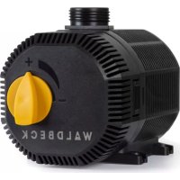
Nemesis T35 - Pump Waldbeck - Free user manual and instructions
Find the device manual for free Nemesis T35 Waldbeck in PDF.

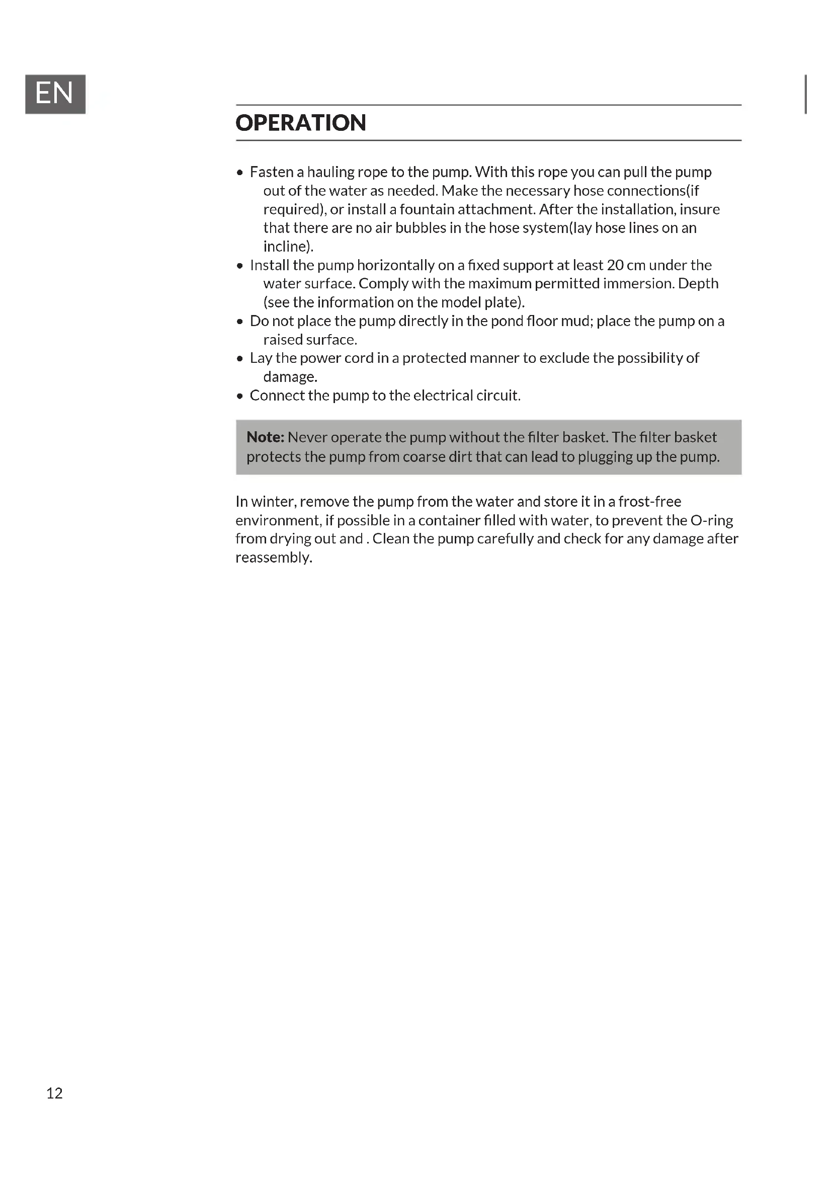


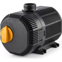
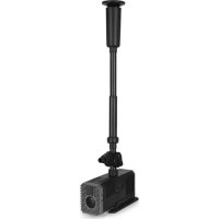
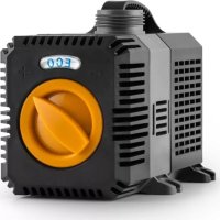
| Product type | Submersible pump for pond, waterfall, fountain or aquarium |
| Brand | Waldbeck |
| Model | Nemesis T35 |
| Power supply | 220 V ~ 50 Hz |
| Power | 35 W |
| Maximum delivery head | 2 m |
| Maximum flow rate | 2000 l/h |
| Maximum water temperature | 50 °C |
| Use | Fresh water only |
| Motor type | Submersible rotor electric motor |
| Filter | Removable front filter basket with sponge |
| Outlet connection | Locking nozzle with large and small fitting |
| Suction cups | 4 suction cups for fixing |
| Included accessories | Rubber base, O-rings, front filter, outlet parts |
| Maintenance | Monthly cleaning of filter and pump |
| Winter storage | Remove from water, clean, store in a container with water in a frost-free place |
| Safety | Never open the motor housing, do not run dry, disconnect before maintenance |
| Standards | CE (EMC, LVD, RoHS) |
| Recycling | Compliant with WEEE directive 2012/19/EU |
Frequently Asked Questions - Nemesis T35 Waldbeck
User questions about Nemesis T35 Waldbeck
0 question about this device. Answer the ones you know or ask your own.
Ask a new question about this device
Download the instructions for your Pump in PDF format for free! Find your manual Nemesis T35 - Waldbeck and take your electronic device back in hand. On this page are published all the documents necessary for the use of your device. Nemesis T35 by Waldbeck.
USER MANUAL Nemesis T35 Waldbeck
10033382 10031918 10033389 10033390
WALDBECK
Nemesis T35 / T45 / T60 / T90
Teichpumpe
Pond Pump
INHALTSVERZEICHNIS
natural_image
Symbol of a trash bin crossed with a diagonal line, no text or numbers presentCongratulations on purchasing this equipment. Please read this manual carefully and take care of the following hints to avoid damages. Any failure caused by ignoring the items and cautions mentioned in the instruction manual is not covered by our warranty and any liability. Scan the QR code to get access to the latest user manual and other information about the product.

CONTENT
Safety Instructions 10
Product Overview 11
Operation 12
Care and Maintenance 13
Troubleshooting 14
Hints on Disposal 14
TECHNICAL DATA
| Item T35 T45 T60 T90 | ||||
| Power supply 220 V ~ 50 Hz | ||||
| Power consumption | 35 W 45 W 60 W 90 W | |||
| Maximum head | 2 m 2,5 m 3 m 4 m | |||
| Flow rate | 2000 L / hour 2700 L/hour 4500 L / hour | 6200 L / hour | ||
DECLARATION OF CONFORMITY

Producer:
This product is conform to the following European Directives:
2014/30/EU (EMC)
2014/35/EU (LVD)
2011/65/EU (RoHS)
SAFETY INSTRUCTIONS
- Read all instructions before using.
- Do not let the cord hang over edge of table counter or touch hot surface.
- If liquid penetrates inside the battery housing, unplug the appliance and have it checked by a qualified technician before it is used again.
- Do not place the appliance close to heating equipment or any heat source, or in a location subjected to excessive dust or mechanical shocks.
- Do not expose the appliance to extreme temperatures. The appliance shall be used in moderate climates.
- The use of attachments that are not recommended by the appliance manufacturer may result in fire, electric shock or personal injury.
- This appliance is not intended for use by persons (including children) with reduced physical, sensory or mental capabilities, or lack of experience and knowledge, unless they have been given supervision or instruction concerning use of the appliances by a person responsible for their safety.
- Children should be supervised to ensure that they do not play with the appliance.
- The appliance is not a toy. Do not let the children play it. Never let children insert foreign objects into the appliance.
- Do not use the appliance for other than intended use. This appliance has been designed solely for domestic use; the manufacturer's liability shall not be engaged in the event of any professional use, by any misuse or by any use not complying with the operating instructions.
- Any altering of the product itself or changing of the components is forbidden.
- Do not connect the pump to any AC voltage power, it is intended ONLY for DC Voltage power.
- Operate in freshwater only (never above 50ircC ).
- Do not strike the solar panel.
- Do not let the pump run dry.

WARNING
Risk of injury! Never open the motor housing, otherwise there is a danger to life.
PRODUCT OVERVIEW
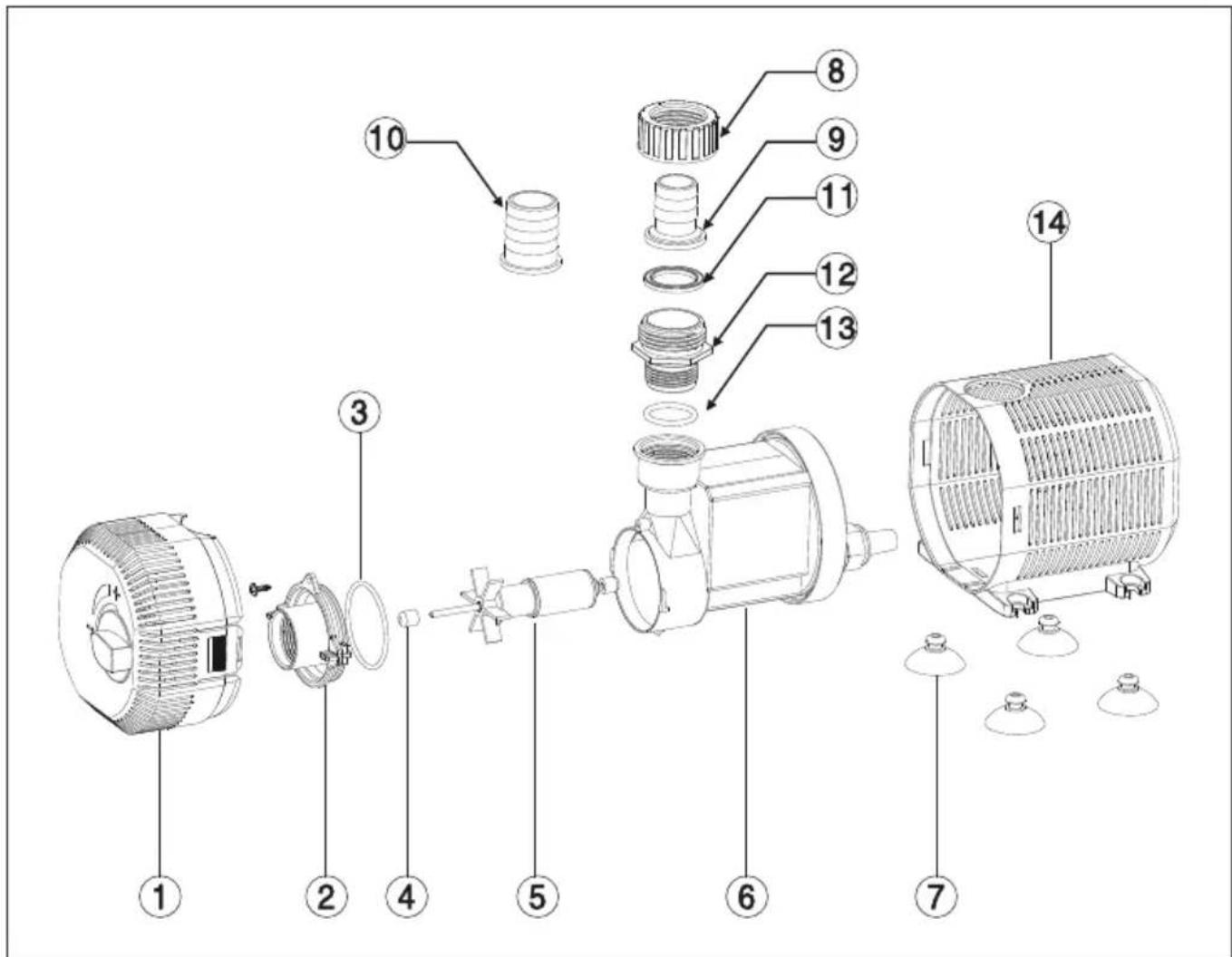
| 1 | Front filter | 8 | Outlet nut |
| 2 | Impeller cover | 9 | Big outlet |
| 3 | O ring 1 | 10 | Small outlet |
| 4 | Rubber bearing | 11 | Gasket |
| 5 | Rotor | 12 | Connecting thread |
| 6 | Motor | 13 O ring 2 | |
| 7 | Suction cup | 14 Big filter | |
OPERATION
- Fasten a hauling rope to the pump. With this rope you can pull the pump out of the water as needed. Make the necessary hose connections(if required), or install a fountain attachment. After the installation, insure that there are no air bubbles in the hose system(lay hose lines on an incline).
- Install the pump horizontally on a fixed support at least 20 cm under the water surface. Comply with the maximum permitted immersion. Depth (see the information on the model plate).
- Do not place the pump directly in the pond floor mud; place the pump on a raised surface.
- Lay the power cord in a protected manner to exclude the possibility of damage.
- Connect the pump to the electrical circuit.
Note: Never operate the pump without the filter basket. The filter basket protects the pump from coarse dirt that can lead to plugging up the pump.
In winter, remove the pump from the water and store it in a frost-free environment, if possible in a container filled with water, to prevent the O-ring from drying out and . Clean the pump carefully and check for any damage after reassembly.
CARE AND MAINTENANCE
Important notes
- Clean the filter housing and the filter sponge once a month and also when the pump capacity is reduced.
- Clean the pump if it is used frequently.
- Never immerse the mains plug in water.
Cleaning the pump
- Disconnect the mains plug.
• Disassemble the fountain group.
• Disassemble the pump casing. - Clean the pump and filter with a soft brush.
- Remove the dirt from the rotor.
Storage in winter
- Remove the pump from the water.
- Check the pump for damage.
- Store the pump in a frost-free environment, if possible in a container filled with water.
TROUBLESHOOTING
| Problem Possible cause Suggested solution | ||
| Pump does not work. No power. Plug in. | ||
| Burned. Allow device to cool down. | ||
| Rotor is blocked. Clear blockages. | ||
| Running without water. Plug in again and add water. | ||
| Noise. Filter housing is blocked or shaft is broken. | Clean blockages after opening. | |
| Ceramic shaft or bearing: Wearing occurs. Change the shaft or bearing. | ||
| Insufficient water displacement. | Impeller broken. Change impeller. | |
| Flow rate valve closed. Open the flow rate valve. | ||
| Filter housing is clogged. Clean blockages and plug in. | ||
| Low voltage. Change to right voltage. | ||
HINTS ON DISPOSAL

natural_image
Symbol of a trash bin crossed with a diagonal line, no text or numbers presentAccording to the European waste regulation 2012/19/EU this symbol on the product or on its packaging indicates that this product may not be treated as household waste. Instead it should be taken to the appropriate collection point for the recycling of electrical and electronic equipment. By ensuring this product is disposed of correctly, you will help prevent potential negative consequences for the environment and human health, which could otherwise be caused by inappropriate waste handling of this product. For more detailed information about recycling of this product, please contact your local council or your household waste disposal service.
Estimado cliente:
ÍNDICE DE CONTENIDOS
| 1 | Filtro frontal | 8 | Tuerca final |
| 2 | Carcasa del propulsor | 9 | Pieza de salida grande |
| 3 | Junta tórica 1 | 10 | Pieza de salida pequeña |
| 4 | Cojinete de goma | 11 | Junta |
| 5 | Rotor | 12 | Pieza de unión grande |
| 6 | Motor | 13 Junta tórica 2 | |
| 7 | Ventosa | 14 Filtro grande |
natural_image
Symbol of a trash bin crossed with a diagonal line, representing no waste or discharge (no text or labels)SOMMAIRE
DÉCLARATION DE CONFORMITÉ

Fabricant :
natural_image
Symbol of a trash bin crossed with a diagonal line, no text or numbers presentINDICE
natural_image
Symbol of a trash bin crossed with a diagonal line, no text or numbers present
- WALDBECK
- INHALTSVERZEICHNIS
- CONTENT
- DECLARATION OF CONFORMITY
- SAFETY INSTRUCTIONS
- WARNING
- PRODUCT OVERVIEW
- OPERATION
- CARE AND MAINTENANCE
- Important notes
- Cleaning the pump
- Storage in winter
- TROUBLESHOOTING
- HINTS ON DISPOSAL
- Estimado cliente:
- ÍNDICE DE CONTENIDOS
- SOMMAIRE
- DÉCLARATION DE CONFORMITÉ
- INDICE
Brand : Waldbeck
Model : Nemesis T35
Category : Pump