
UMC435 - Multitools Honda - Free user manual and instructions
Find the device manual for free UMC435 Honda in PDF.
| Product type | Multi-function power unit |
| Brand | Honda |
| Model | UMC435 |
| Engine | GX35T, 4-stroke, single-cylinder, 35.8 cc |
| Net power output | 1.0 kW at 7,000 rpm |
| Max net torque | 1.6 Nm at 5,500 rpm |
| Idle speed | 3,100 ± 200 rpm |
| Max shaft speed | ≥ 10,000 rpm |
| Fuel type | Unleaded gasoline, research octane number ≥ 91 |
| Fuel tank capacity | 0.63 L |
| Engine oil capacity | 0.10 L (SAE 10W-30 recommended) |
| Ignition system | Transistor magneto |
| Spark plug | CMR5H (NGK) - gap 0.6-0.7 mm |
| Cooling system | Forced air |
| Clutch | Centrifugal |
| Dimensions (L × W × H) | 1 145 × 320 × 255 mm |
| Dry weight | 6.0 kg |
| Compatible accessories | Brush cutter, line trimmer, pole pruner, blower, hedge trimmer, edger, cultivator |
| Safety | Harness, quick attachment, engine ON/OFF control, ear protection, goggles, gloves recommended |
| Periodic maintenance | Oil change every 100 h, air filter cleaning, spark plug check, throttle cable adjustment |
| Warranty | Manufacturer warranty, Honda genuine parts recommended |
Frequently Asked Questions - UMC435 Honda
User questions about UMC435 Honda
0 question about this device. Answer the ones you know or ask your own.
Ask a new question about this device
Download the instructions for your Multitools in PDF format for free! Find your manual UMC435 - Honda and take your electronic device back in hand. On this page are published all the documents necessary for the use of your device. UMC435 by Honda.
USER MANUAL UMC435 Honda
Read and understand this Owner's Manual before operating the power head.
ECOLOGY CONSCIOUS TECHNOLOGY
Honda UMC425E·UMC435E
UMC425U·UMC435U
OWNER'S MANUAL
Original instructions
MANUEL DE L'UTILISATEUR
Notice originale
Thank you for purchasing a Honda power head.
Honda power heads UMC425E, UMC435E, UMC425U, and UMC435U can be used by attaching different kinds of Honda approved attachments to enable various operations.
This manual covers the operation and maintenance of the Honda power head UMC425E · UMC435E · UMC425U · UMC435U.
Honda Motor Co., Ltd. reserves the right to make changes at any time without notice and without incurring any obligation.
No part of this publication may be reproduced without written permission.
This manual should be considered a permanent part of the power head and should remain with it if it is resold.
Pay special attention to statements preceded by the following words;
WARNING Indicates a strong possibility of severe personal injury or death if instructions are not followed.
CAUTION: Indicates a possibility of personal injury or equipment damage if instructions are not followed.
NOTE: Gives helpful information.
If a problem should arise, or if you have any questions about the power head, consult an authorized Honda dealer.
Honda power heads are designed to give safe and dependable service if operated according to instructions.
WARNING
Operating a power head requires special effort to ensure the safety of the operator and the safety of others. Read and understand this Owner's Manual before operating the power head; failure to do so could result in personal injury or equipment damage.
The illustrations herein are mainly based on: UMC435E
- The illustrations may vary according to the type.
Disposal
To protect the environment, do not dispose of this product, battery, engine oil, etc. carelessly by leaving them in the waste. Observe the local laws and regulations or consult your authorized Honda dealer for disposal.
1.SAFETYINSTRUCTIONS. 3
2.SAFETYLABELLOCATIONS 11
3. COMPONENT IDENTIFICATION 13
4.CONTROLS 15
5. PRE-OPERATION CHECKS 19
6. STARTING THE ENGINE 34
7. OPERATION 38
8. STOPPING THE ENGINE 39
9.MAINTENANCE 40
10.TRANSPORTING 54
11.STORAGE 55
12.TROUBLESHOOTING 57
13. SPECIFICATIONS 58
MAJOR Honda DISTRIBUTOR ADDRESSES . Inside back cover
"EC Declaration of Conformity"
WARNING
To ensure safe operation
For your safety and safety of others, pay special attention to these precautions:


- Honda power head is designed to give safe and dependable service if operated according to instructions.
Read and understand the Owner's Manual before operating the power head. Failure to do so could result in personal injury or equipment damage.
Gasoline is extremely flammable and is explosive under certain conditions.
- Do not smoke or allow flames or sparks in the area where the power head is refueled or where gasoline is stored.
- Do not overfill the fuel tank, and make sure the fuel tank cap is closed securely after refueling.
- Refuel in a well-ventilated area with the engine stopped.

- Exhaust contains poisonous carbon monoxide, a colorless, odorless gas. Breathing carbon monoxide can cause loss of consciousness and may lead to death.
- If you run the power head in an area that is confined, or even partially enclosed area, the air you breathe could contain a dangerous amount of exhaust gas.
- Never run your power head inside a garage, house or near open windows or doors.
WARNING
To ensure safe operation
Operator Responsibility
- Only equip Honda approved attachments. If not, injury or accident may occur.
- Read and follow the instructions in the owner's manual that came with each attachments.
- Never operate the power head when tired, ill or under influence of alcohol or other drugs.
- Any part from the machine is a potential source of danger if the machine is used in abnormal conditions or if the maintenance is not done correctly.
- Read the owner's manual carefully. Be familiar with the controls and their proper use of the power head. Know how to stop the engine rapidly.
- Never allow children or people unfamiliar with this owner's manual to use the power head. Local regulations may restrict the age of the operator.
- If you lend or resell your power head to a third person, instruct him or her with how to handle the product and alert him or her to read the Owner's Manual carefully before operation.
-
Never operate the power head while:
-
people, especially children or pets are nearby.
- user is fatigued or under medication, or has swallowed substances known to affect judgement or reactions.
Each attachment have working area which people or animal shall not approach. Follow to the instructions in the owner's manual that comes with each attachment. - Keep in mind that the operator or user is responsible for accidents or hazards occurring to other people or their property.
WARNING
To ensure safe operation
Operator Responsibility
- While operating the power head, always wear protective clothing and protective devices.
-
For protective clothing and protective devices to be worn, follow to the instructions in the owner's manual that comes with each attachment.
-
Protective clothing
Wear adequate clothes with long sleeves and long pants.
The clothes must fit your body and button up or zip up the clothes securely. Do not leave the sleeves and bottom of the shirt/jacket loose.
Wear the arm covers, too.
Do not wear the clothes with the tapes, laces and/or ribbons, loose clothes, necktie, necklace, etc. during operation. Bind your hair if it is long, and do not let your hair below your shoulder.
-
Protective devices
-
Goggles
Wear the goggles or other eye protection to protect your eyes from the debris.
- Helmet
Wear the helmet to protect your head from the overhead branches and the falling foreign material.
- Face shield
Wear face shield to protect your face from the debris.
- Ear muffs/ear plugs
Wear the ear muff, ear plugs or other hearing protection to protect your ears from the noise.
- Gloves
Wear the gloves to protect your hands.
-
Safety boots
-
Wear the safety boots with the non-slip sole and toe protector to protect your feet from the flying debris.
Do not operate the equipment when barefoot or wearing open sandals.
Wear the leg protectors as well.
WARNING
To ensure safe operation
Operator Responsibility
*Dust mask
We recommend that you wear the dust mask if you suffer from the allergic rhinitis, e.g. pollinosis, etc. The dust mask is available at a pharmacy and it is helpful for reducing the amount of pollens you breathe.

- Before each use, visually inspect the power head for any damage and looseness of fastening part.
- Before each use, look around and underneath the engine for signs of oil or gasoline leaks.
- Avoid operating the power head at night or in a bad weather of poor visibility, because there is much possibility of accident.
- Walk, never run during operation.
- Avoid operating the power head on a steep slope.
The steep slope is very slippery, so you can slip down.
WARNING
To ensure safe operation
Operator Responsibility
- Do not operate the power head with the labels, and other parts removed.
- Do not mount any incorrect parts and do not tamper with the power head as it can result in personal injury and/or equipment damage. Use the parts that are designed for your model and application.
-
Stop the engine with the engine switch to the OFF position in the following cases:
-
Before any operation around the power head.
- Before checking, cleaning or working on the power head.
- After striking a foreign object. Inspect the power head for damage and make repairs before restarting and operating the power head again.
- If power head starts to vibrate abnormally. Check immediately the cause of the vibration and perform the necessary repair.
- Whenever you leave the power head unattended.
- Before refuelling.
- When any person or pet is approaching.
-
Shut off the engine immediately when the power head shows abnormal vibration suddenly. Sudden vibration can suggest the damaged rotating parts or loose fasteners. Examine the cause of the problem, and do not start the engine before repair is made.
-
The power head is faulty when the engine is idling by returning the throttle but the attachment keeps turning, and idle speed adjustment must be made. Consult your authorized Honda dealer.
- Keep all nuts, bolts and screws tight to be sure the power head is in safe working condition. Regular maintenance is an essential aid to user's safety and retaining a high level of performance.
- Do not use the power head with worn or damaged parts. Parts must be replaced, or repaired. Replace worn or damaged parts with Honda genuine parts. Non equivalent quality parts may damage the machine and be prejudicial to your safety.
WARNING
To ensure safe operation
Operator Responsibility
- Injury caused by vibration and cold:
You may feel the prickling or burning pain in your fingers, and the fingers may lose color and feeling depending on your constitution. It is believed that these symptoms are brought by vibration and/or exposure to cold. The specific trigger point of these symptoms are not identified yet, but observe the following instructions.
- Limit the amount of time you spend operating the power head in a day.
A day's work should consist of the work with the power head and the other work without the hand-held equipment so you can limit the amount of time when your hands are exposed to the machine vibration.
- Keep your body warm, especially your hands, wrists and arms.
- Take your breaks at shorter intervals and arm exercises well to maintain good blood circulation. Do not smoke while working.
-
When you feel discomfort, redness and swelling of the fingers followed by whitening and loss of feeling, consult your doctor promptly.
-
Injury caused by repeated operation:
Performing the repeated operation for a prolonged time may cause injury. Observe the following instructions to reduce the causes of the injury.
- Avoid the repeated operation by using your wrist(s) in bent, stretched or twisted position.
- Take your breaks regularly to minimize the effect of the repeated operation. Take your time when performing the repeated operation. Do not rush to operate the power head.
- When your fingers, hands, wrists and/or arms are throbbing or numbed, consult your doctor.
WARNING
To ensure safe operation
Child Safety
- Keep children indoors and supervised at all times when any outdoor power head is being used nearby. Young children move quickly and are attracted especially to the power head activity.
- Never assume children will remain where you last saw them. Be alert and turn the power head off if children enter the area.
- Children should never be allowed to operate the power head, even under adult supervision.
Fire and Burn Hazard
Gasoline is extremely flammable, and gasoline vapor can explode. Use extreme care when handling gasoline. Keep gasoline out of reach of children.
- Store fuel in containers specifically designed for this purpose.
- Refuel outdoors only, and do not smoke while refuelling or handling fuel.
- Add fuel before starting the engine. Never remove the cap of the fuel tank or add petrol while the engine is running or when the engine is hot.
- If gasoline is spilled, do not attempt to start the engine but move the power head away from the area of spillage and avoid creating any source of ignition until gasoline vapours have dissipated.
- Tighten all fuel tanks and container caps securely.
- When you start the engine after refueling, be sure to start the engine at least 3m (10 feet) away from the refueling spot.
- Never store the power head with gasoline in the tank inside a building where fumes may reach an open flame, spark or high temperature source.
- Allow the engine to cool before storing in any enclosure.
- To reduce the fire hazard, keep the power head, especially the engine, muffler, the gasoline storage area as well, free of grass, leaves, or excessive grease.
Do not leave containers of vegetable matters in or near a building.
- If the fuel tank has to be drained, this should be done outdoors, with a cold engine.
WARNING
To ensure safe operation
Carbon Monoxide Poisoning Hazard
Exhaust contains poisonous carbon monoxide, a colorless and odorless gas. Breathing exhaust can cause loss of consciousness and may lead to death.
- If you run the engine in an area that is confined or even partially enclosed, the air you breathe could contain a dangerous amount of exhaust gas. To keep exhaust gas from building up, provide adequate ventilation.
- Replace faulty muffler.
- Do not operate the engine in a confined space where dangerous carbon monoxide fumes can collect.
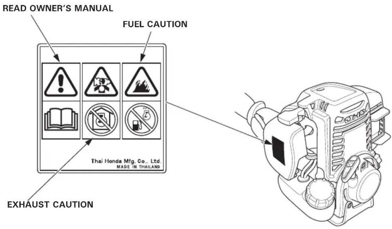
Your power head must be used with care. Therefore, decals have been placed on the machine, to remind you pictorially of main precautions to take during use. Their meanings are explained on page 3.
These decals are considered as a part of the power head. Should one become detached or unreadable, contact your Honda dealer for its replacement.
For European model: UMC425E, UMC435E
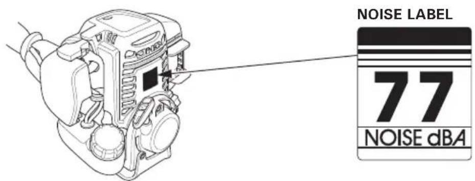
CE mark and noise label locations
For European model:
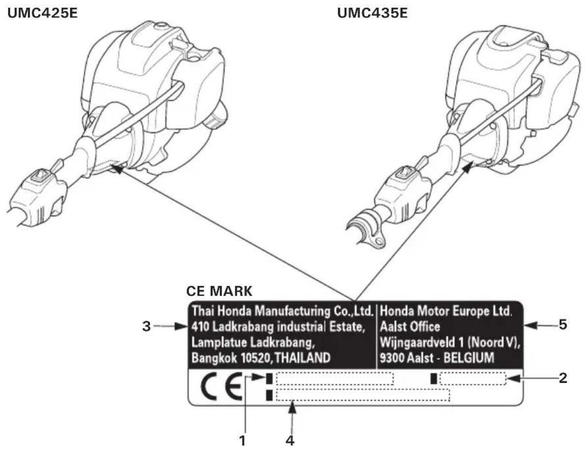
- Model and Type
- Year of manufacture
- Manufacturer and address
- Frame serial number
- Name and address of authorized representative
*The noise label is affixed to the attachments.
For Australian model:
Example: UMC435E
*The following attachments can be used with the power head.
- Brush cutter
Hedge trimmer
-
Grass trimmer
-
Edger
Pruner
Cultivator
Blower
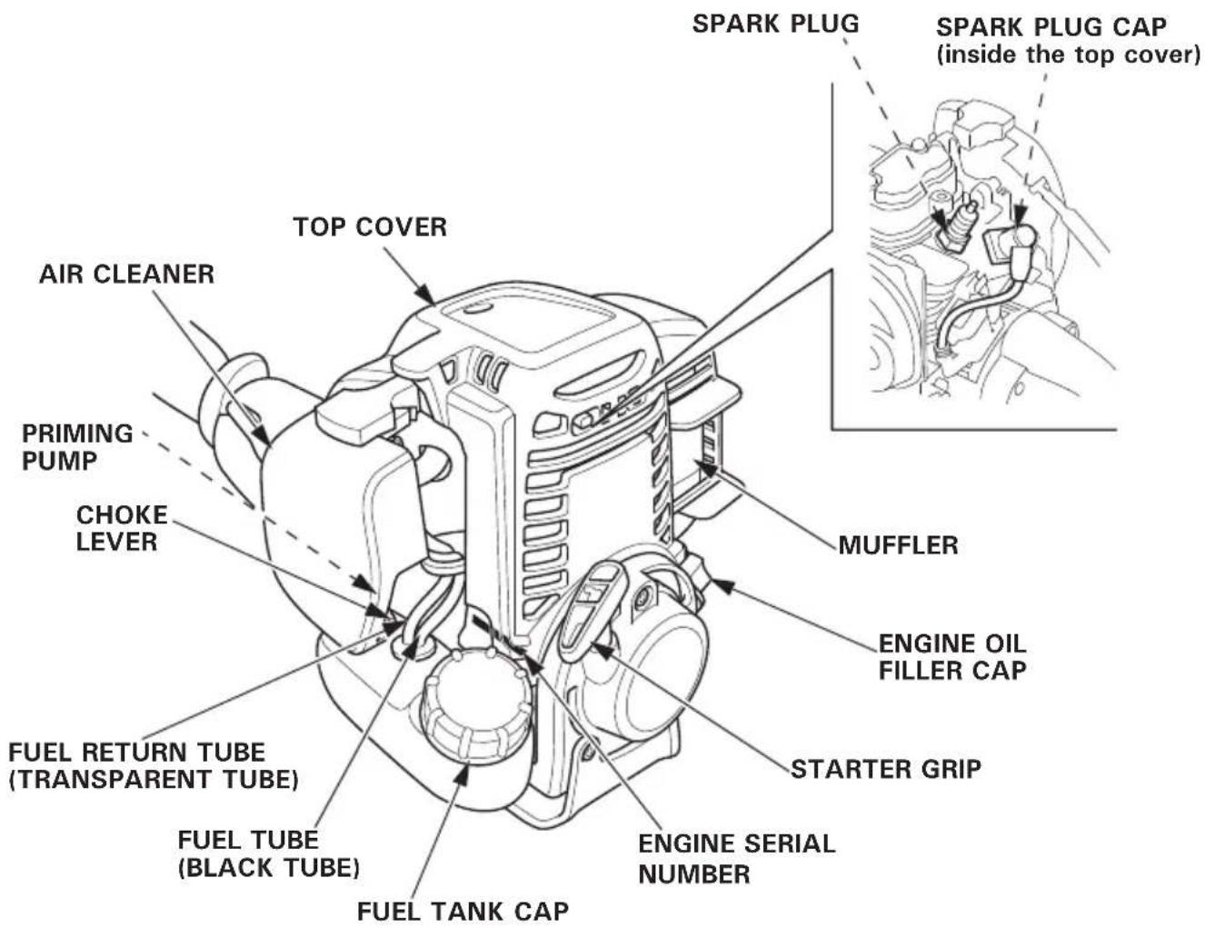
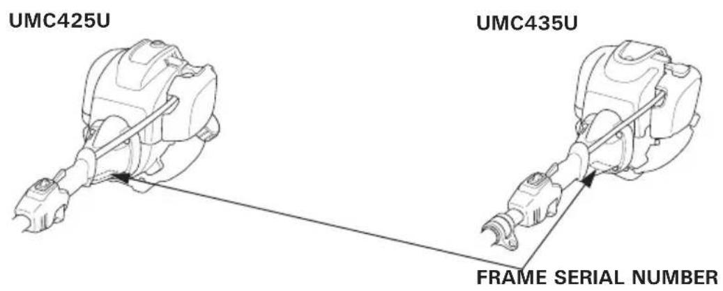
Record the frame serial number (see pages 12 and 14) and the engine serial number in the space below. You will need these numbers when ordering parts.
Frame serial number:
Engine serial number:
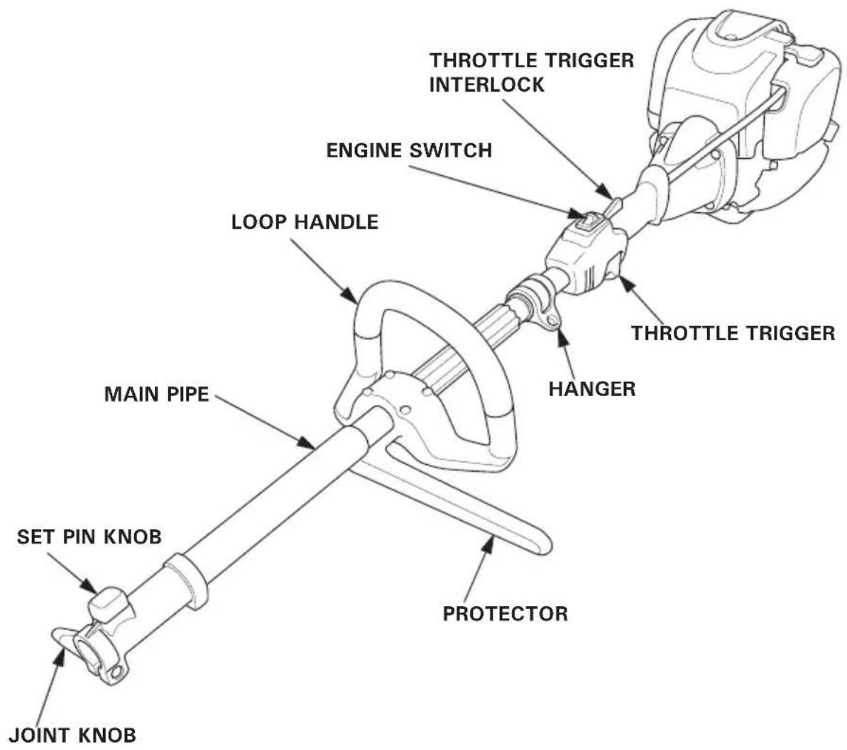
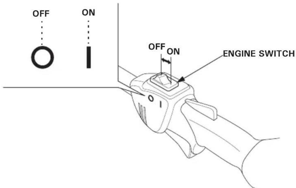
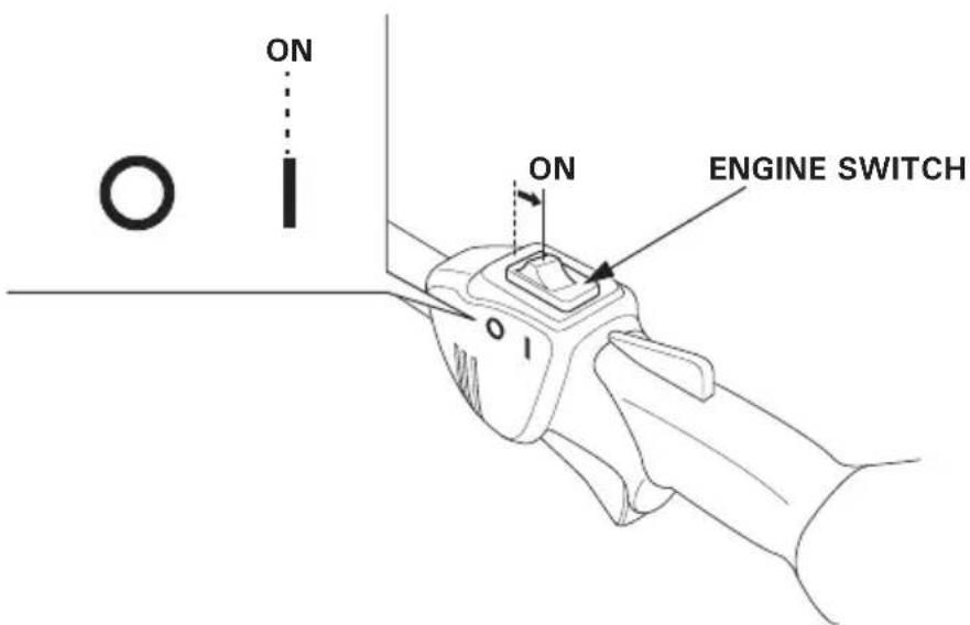
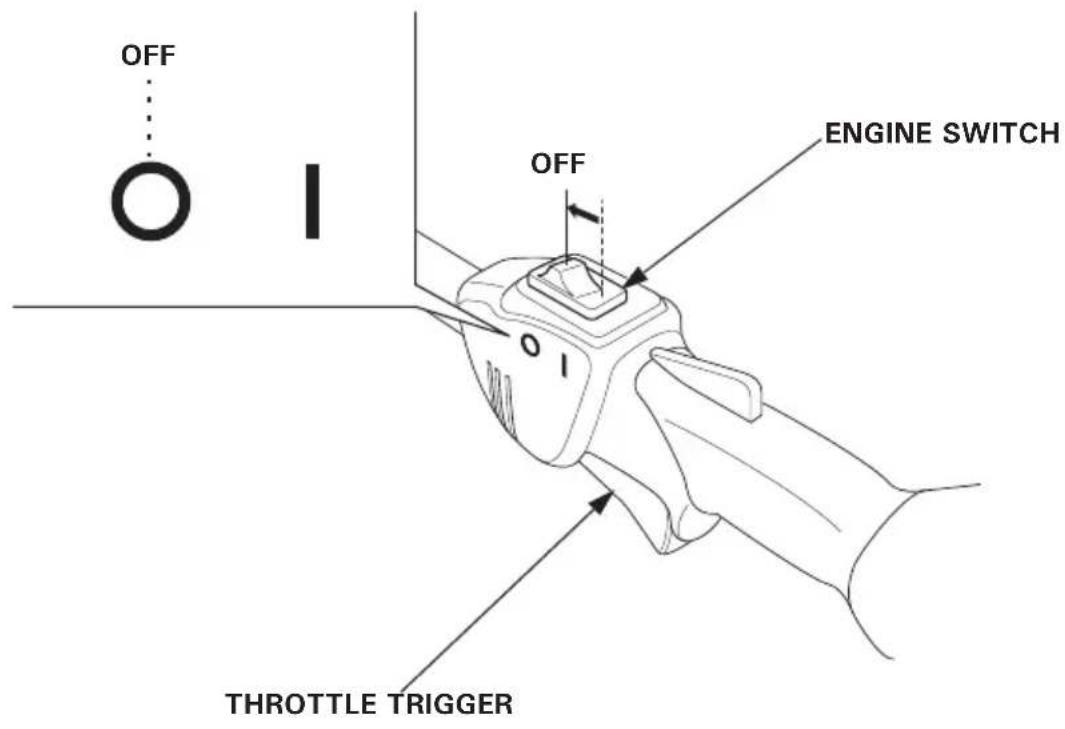
1. Engine switch
The engine switch enables and disables the ignition system.
The engine switch must be in the ON position for the engine to run.
Moving the engine switch to the OFF position stops the engine.
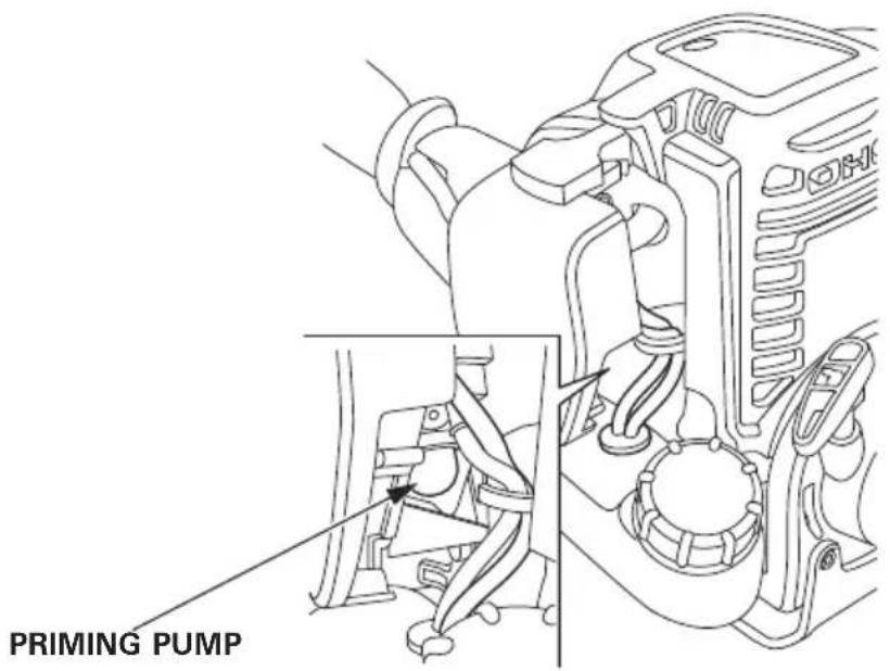
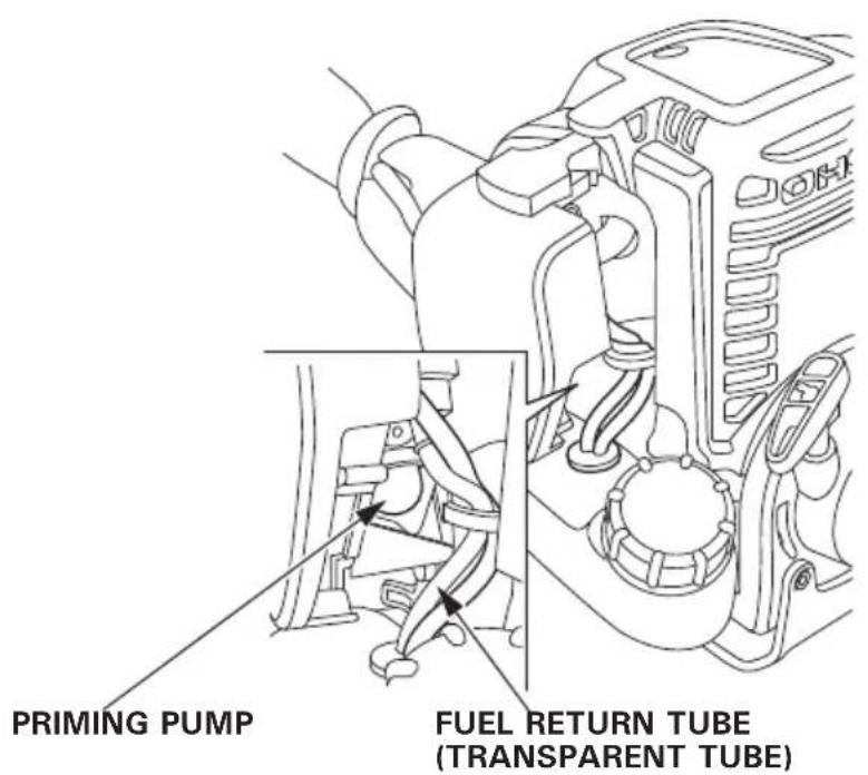
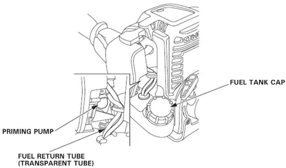
2. Priming pump
Pressing the priming pump feeds the gasoline from the fuel tank to the carburetor. This procedure is necessary for starting the engine.
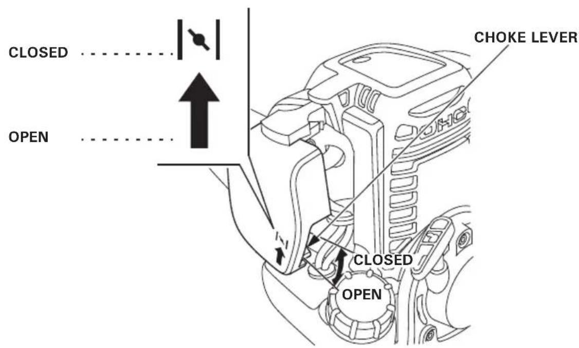
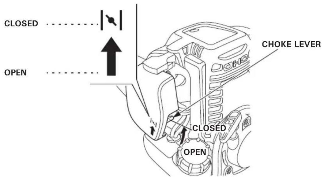
3. Choke lever
The choke lever opens and closes the choke valve in the carburetor.
The CLOSED position enriches the fuel mixture for starting a cold engine.
The OPEN position provides the correct fuel mixture for operation after starting, and for restarting a warm engine.
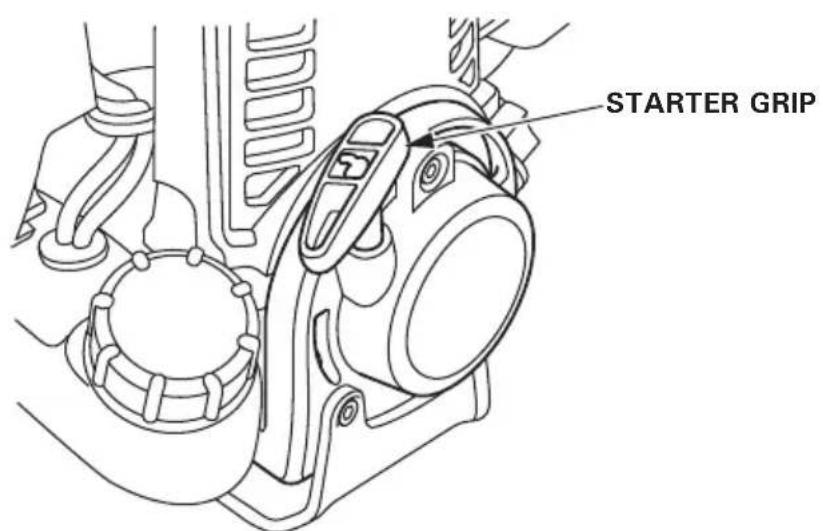
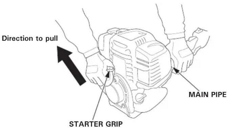
4. Starter grip
Pulling the starter grip operates the recoil starter to crank the engine for starting.
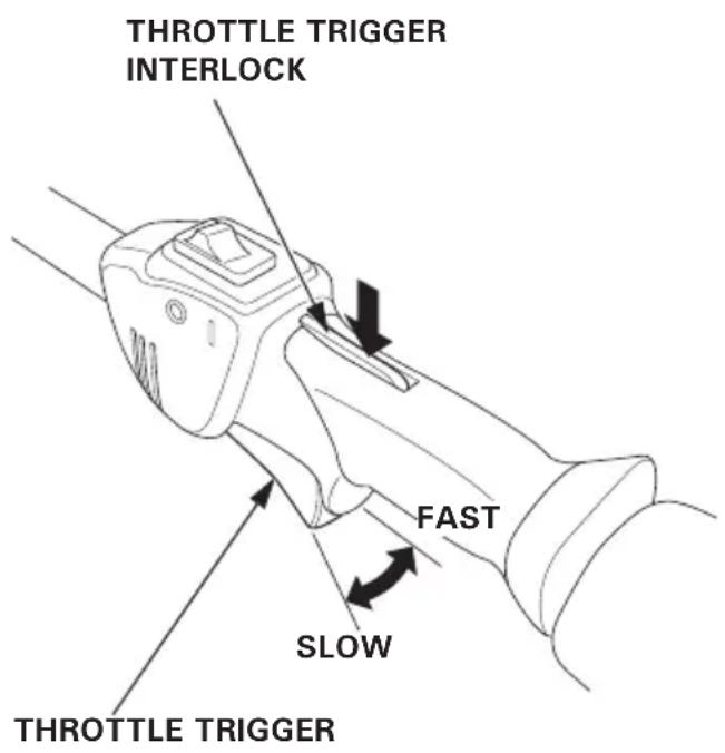
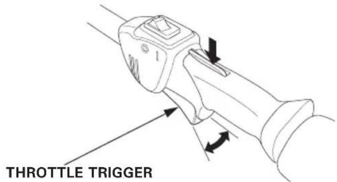
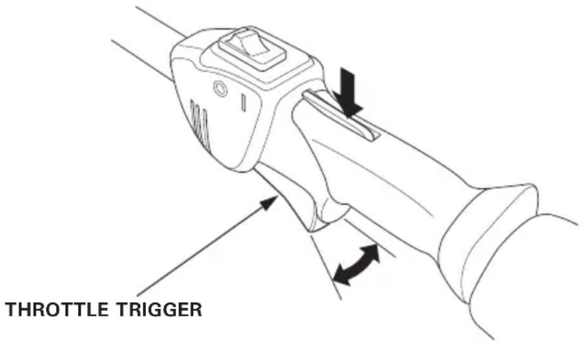
5.Throttle trigger
The throttle trigger controls engine speed.
Pulling and releasing the throttle trigger shown below makes the engine run faster or slower.
NOTE:
The throttle trigger interlock must be depressed before the throttle trigger can be activated.
By pulling the throttle trigger gradually, the engine speed increases.
Pull the throttle trigger more to accelerate the engine speed.
By releasing the throttle trigger, the engine speed decreases.
Throttle trigger interlock:
The throttle trigger interlock makes the throttle trigger operable. The throttle trigger cannot be pulled unless the throttle trigger interlock has been pushed beforehand.
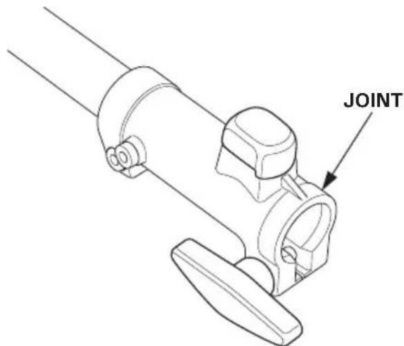
6.Joint
The joint is to attach Honda approved attachment to the power head. Refer to Pages 30-32 for how to attach and detach the attachments.
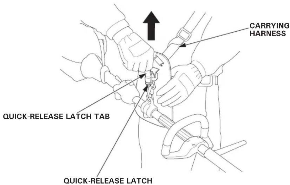
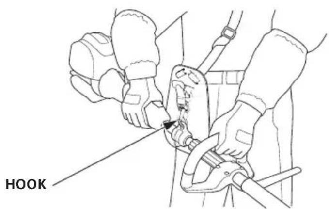
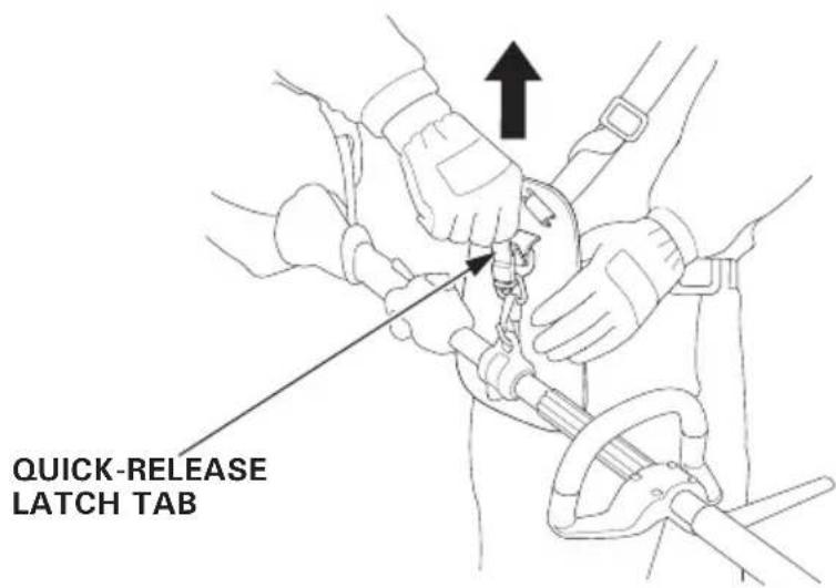
7.Quick-release latch
The quick-release latch tab is provided to detach the power head from your body in an emergency.
Pull up the quick-release latch tab, and the power head is detached from the carrying harness.
For safe and efficient operation, always make a pre-operation inspection before operating:
WARNING
Perform a pre-operation inspection on a firm, level surface with the engine stopped and make sure that the engine switch is in the OFF position.
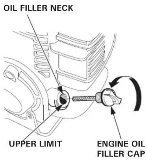
- Check the engine oil level
CAUTION:
Running the engine with low oil level will cause serious engine damage.
Check the engine oil level before each use, or every 10 hours if operated continuously.
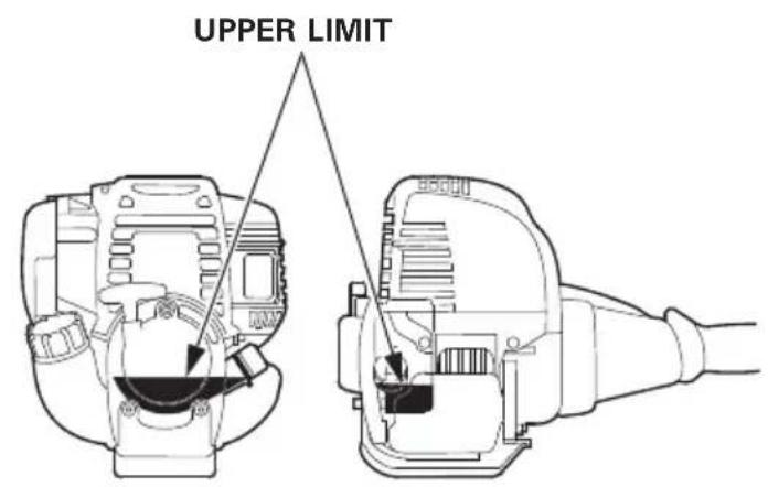
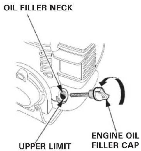
- Place the power head on a level surface and remove the oil filler cap.
- Check the oil level. If it is below the upper limit, fill with the recommended oil to the upper limit.
3.Reinstall the oil filler cap securely.
ENGINE OIL CAPACITY
UMC425E, UMC425U: 0.08 L (0.08 US qt, 0.07 Imp qt)
UMC435E, UMC435U: 0.10 L (0.11 US qt, 0.09 Imp qt)
Use 4-stroke motor oil that meets or exceeds the requirements for API service classification SE or later (or equivalent). Always check the API service label on the oil container to be sure it includes the letters SE or later (or equivalent).
SAE 10W-30 is recommended for general use. Other viscosities shown in the chart may be used when the average temperature in your area is within the indicated range.

CAUTION:
Using nondetergent oil or 2-stroke engine oil could shorten the engine's service life.
2. Check the fuel level
Use automotive unleaded gasoline with a Research Octane Number of 91 or higher (a Pump Octane Number of 86 or higher).
Never use stale or contaminated gasoline or an oil/gasoline mixture.
Avoid getting dirt or water in the fuel tank.
WARNING
- Gasoline is extremely flammable and is explosive under certain conditions.
- Refuel in a well-ventilated area with the engine stopped. Do not smoke or allow flames or sparks in the area where the engine is refueled or where gasoline is stored.
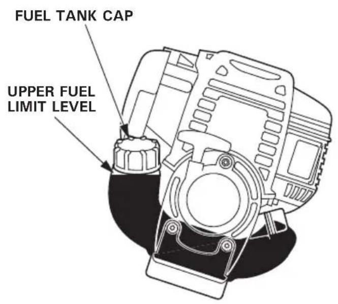
- Do not overfill the fuel tank (there should be no fuel in the filler neck). After refueling, make sure the tank cap is closed properly and securely.
- Be careful not to spill fuel when refueling. Spilled fuel or fuel vapor may ignite. If any fuel is spilled, make sure the area is dry before starting the engine.
- Avoid repeated or prolonged contact with skin or breathing of vapor. KEEP OUT OF REACH OF CHILDREN.
CAUTION:
Gasoline substitutes are not recommended; they may be harmful to fuel system components.
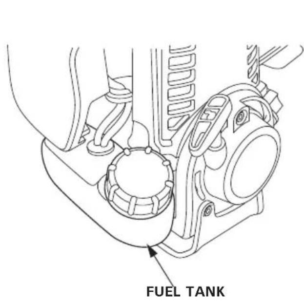
- Check the fuel level visually from the outside of the fuel tank while keeping the fuel filler neck upright.
2.If the fuel level is low, refuel the fuel tank until the level as specified. Remove the fuel tank cap gradually to release a pressurized air in the fuel tank. Fuel in the fuel tank may spout out, if the fuel tank cap is removed quickly.
NOTE:
Gasoline spoils very quickly depending on factors such as light exposure, temperature and time.
In worst cases, gasoline can be contaminated within 30 days.
Using contaminated gasoline can seriously damage the engine (carburetor clogged, valve stuck).
Such damage due to spoiled fuel is disallowed from coverage by the warranty.
To avoid this please strictly follow these recommendations:
- Only use specified gasoline (see page 21).
- Use fresh and clean gasoline.
- To slow deterioration, keep gasoline in a certified fuel container.
- If long storage (more than 30 days) is foreseen, drain fuel tank and carburetor (see pages 55 and 56).
Gasolines containing alcohol
If you decide to use a gasoline containing alcohol (gasohol), be sure its octane rating is at least as high as that recommended by Honda.
There are two types of "gasohol": one containing ethanol, and the other containing methanol.
Do not use gasohol that contains more than 10% ethanol.
Do not use gasoline containing more than 5% methanol (methyl or wood alcohol) and that does not also contain co-solvents and corrosion inhibitors for methanol.
NOTE:
- Fuel system damage or engine performance problems resulting from the use of gasoline that contains more alcohol than recommended is not covered under the warranty.
- Before buying gasoline from an unfamiliar station, first determine if the gasoline contains alcohol, if it does, find out the type and percentage of alcohol used.
If you notice any undesirable operating symptoms while using a particular gasoline. Switch to a gasoline that you know contains less than the recommended amount of alcohol.
3. Check the air cleaner
CAUTION:
Never run the engine without the air cleaner; rapid engine wear will result.
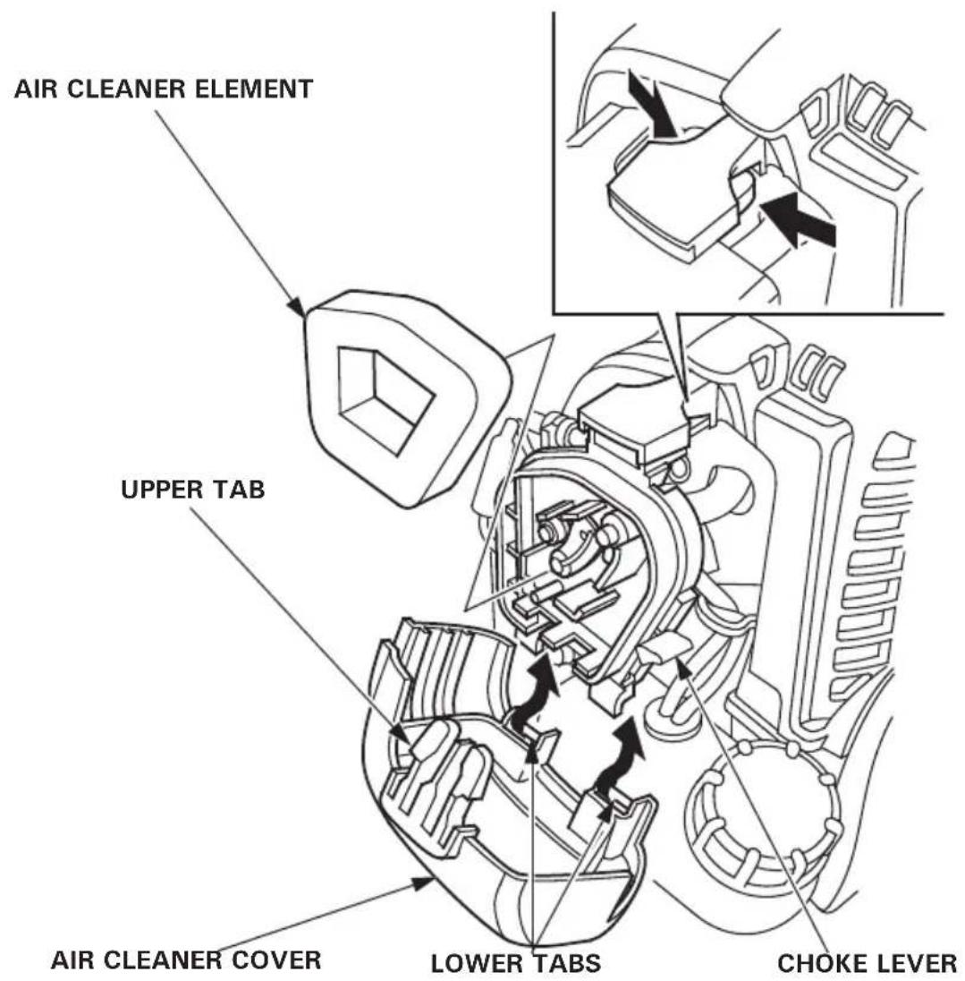
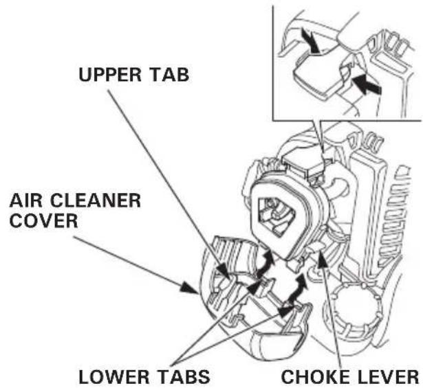
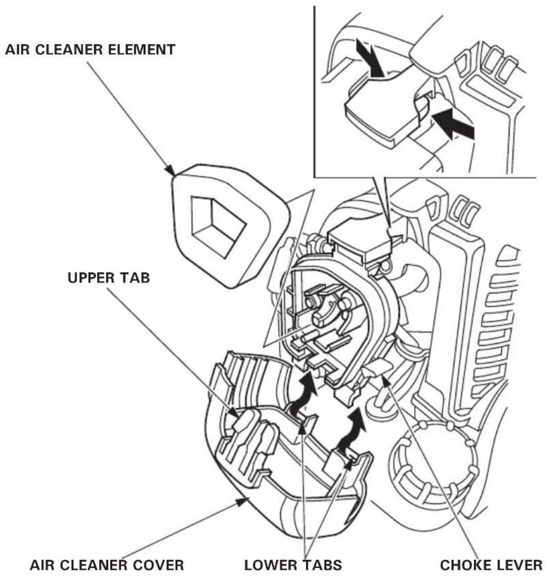
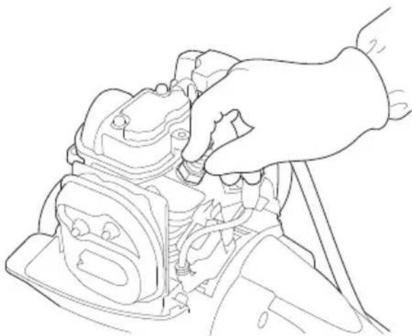
- Move the choke lever to the CLOSED (upwards) position.
- Remove the air cleaner cover by unhooking the upper tab on the top of the air cleaner cover and its two lower tabs.
- Check the air cleaner element for dirt or obstruction. Clean the air cleaner element, if it is dirty (see page 45).
4.Reinstall the air cleaner element. - Reinstall the air cleaner cover by inserting the lower tabs, then insert the upper tab.
4. Check the throttle cable free play
- Move the choke lever to the CLOSED (upwards) position.
- Remove the air cleaner cover by unhooking the upper tab on the top of the air cleaner cover and its two lower tabs.
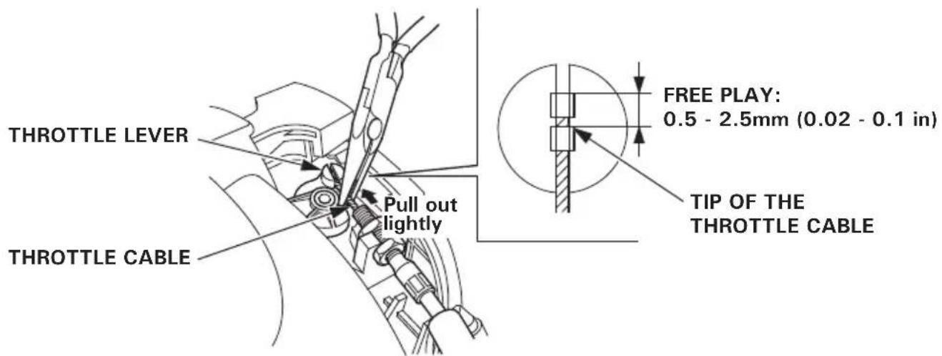
3.Pull out the throttle cable lightly and check the extended length of the throttle cable at the end of the cable. It should be 0.5 - 2.5mm (0.02-0.1 in). (Take care not to damage the throttle cable.) Adjust if the measurement exceeds the specification (see page 49).
-
Operate the throttle system several times and check it has the free play (i.e. throttle lever does not move while operating the throttle trigger).
-
Check the throttle trigger operates smoothly and always spring back to the idle position.
If there is any abnormality, the throttle system must be serviced. Consult with your authorized Honda dealer.
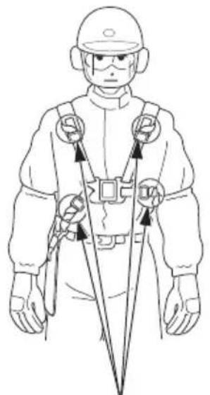
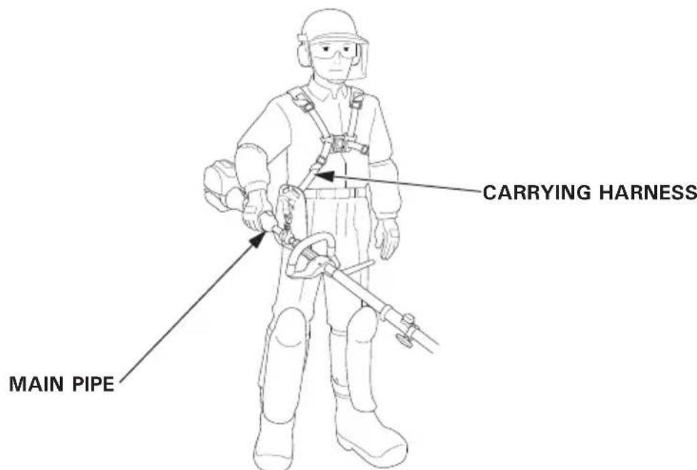
5. Adjustment of the carrying harness
WARNING
Be sure to wear the carrying harness before using the power head. Otherwise, injuries might occur due to its instability.
-
Wear the carrying harness so that the hip pad is on the right side of your body
-
Make sure the harness does not twist.
- If the carrying harness is for both shoulders, firmly secure the carrying harness latch on the front of your body until it clicks. To unlock the carrying harness latch, pull the harness to the right and to the left while pressing the latch.


- Adjust the length of the harness as shown in the figures below.
To make it shorter
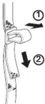
To make it longer
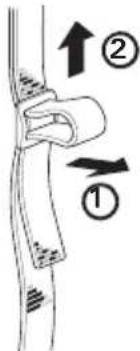
- Roll the end of the harness toward your body and fasten it.
(UMC435E·UMC435U)
Roll the end of the harness and fasten it.
(There is one applicable point on the back side of your body)

Roll the end of the harness and fasten it.
6. Check the quick-release latch
1.Put on the carrying harness.
2. Check the latch is released as soon as the quick-release latch tab is pulled upwards while holding the hip pad with your left hand.
3.Insert the latch tongue in the slot of the quick-release latch to reattach the power head to the carrying harness.
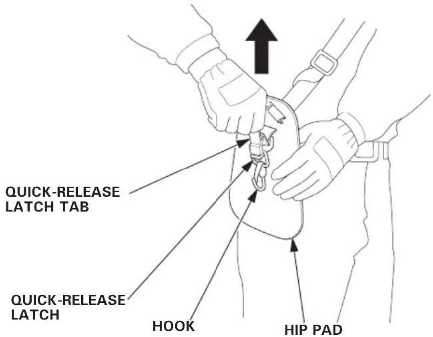
If the latch is not released, have your device inspected and repaired by your servicing dealer.
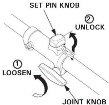
7. Attachment installation/removal
Check the joint area :
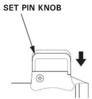
- Check if the set pin knob moves smoothly.
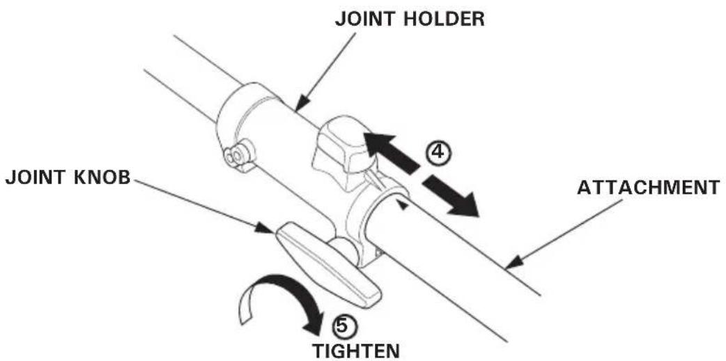
- Check if the joint knob tightens and loosens smoothly, and if there is no any damage.
3.Make sure there is no debris in the groove and inside the joint holder.
Installation:
WARNING
The engine shall not be started until the attachment is attached to the power head. Otherwise, injuries might occur, for example, when your fingers touch the joint opening.
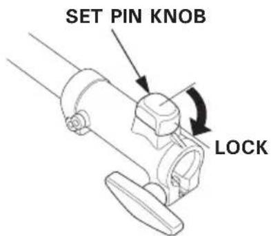
- Put the set pin knob to the lock position and loosen the joint knob.
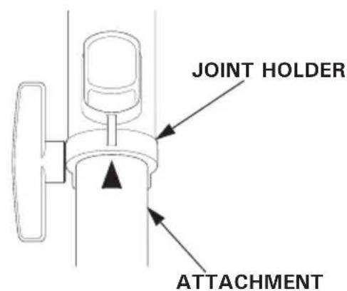
- Align the " mark on the attachment with the joint projection. Or, align the key of the attachment with the joint groove.

3.Insert the attachment until the set pin knob clicks. Confirm the "▲" mark on the attachment is at the joint holder end.
4.Pull the attachment and joint holder to the arrow direction to check that the attachment will not come loose.
5.Tighten the joint knob.
CAUTION:
When you place the power head with the recoil starter facing down, be careful not to make impact to the recoil starter. Recoil starter or the engine might get damaged from the impact.
Removal:
WARNING
Be sure to turn off the engine switch. Confirm that the engine and the attachment is completely stopped before detaching the attachment. If the attachment is still moving, personal injury or equipment damage may occur.
- Loosen the joint knob.
2.Pull up the set pin knob to the unlock position.
3.Hold the main pipe on the power head side and detach the attachment.
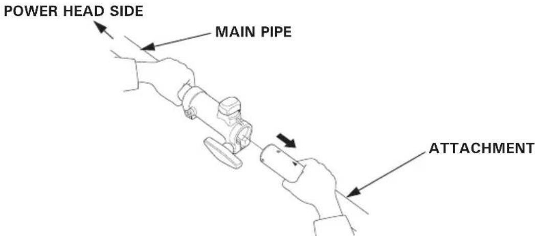
4.Put the set pin knob to the lock position.
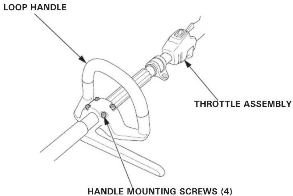
8. Check all bolts and nuts
-
Check each bolt and nut for looseness. Tighten them securely if necessary.
-
Check the handle for loose mounting bolts or screws, and tighten them securely if necessary.
WARNING
- Exhaust gas contains poisonous carbon monoxide. Never run the engine in an enclosed area. Be sure to provide adequate ventilation.
-
Start the engine in a place away from the people, pets, and surrounding buildings. Be sure there are no obstacles in the working area.
-
Move the engine switch to the ON position.
- To start a cold engine, move the choke lever to the CLOSED position.
To restart warm engine, leave the choke lever in the OPEN position.
NOTE:
Do not use the choke if the engine is warm or the air temperature is high.
- Press the priming pump several times until a flow in the fuel return tube (transparent tube) is visually noticed.
4.Pull the starter grip lightly until you feel resistance while holding the main pipe, then pull briskly in the direction of the arrow as shown below. Return the starter grip gently.
CAUTION:
-
Do not allow the starter grip to snap back against the engine. Return it gently to prevent damage to the starter.
-
Damage may result if the starter grip is pulled while the engine is running.
5.If the choke lever has been moved to the CLOSED position to start the engine, gradually move it to the OPEN position as the engine warms up.

Carburetor Modification for High Altitude Operation.
At high altitude, the standard carburetor air-fuel mixture will be too rich. Performance will decrease, and fuel consumption will increase. A very rich mixture will also foul the spark plugs and cause hard starting. Operation at an altitude that differs from that at which this engine was certified, for extended periods of time, may increase emissions.
High altitude performance can be improved by specific modifications to the carburetor. If you always operate your power head at altitudes above 1,500 meters (5,000 feet), have your dealer perform this carburetor modification. This engine, when operated at high altitude with the carburetor modifications for high altitude use, will meet each emission standard throughout its useful life.
Even with carburetor modification, engine horsepower will decrease about 3.5% for each 300-meter (1,000-foot) increase in altitude. The effect of altitude on horsepower will be greater than this if no carburetor modification is made.
CAUTION:
When the carburetor has been modified for high altitude operation, the air-fuel mixture will be too lean for low altitude use. Operation at altitudes below 1,500 meters (5,000 feet) with a modified carburetor may cause the engine to overheat and result in serious engine damage. For use at low altitudes, have your servicing dealer return the carburetor to original factory specifications.
7. OPERATION
Read and understand the safety instructions on pages 3 to 10 before operating the power head.
If you notice any abnormal sound, smell, vibration, or other unusual signs, stop the engine immediately and consult your authorized Honda dealer.
With the engine idling, hook the power head to your carrying harness and hold the power head at the correct position.
Hold the power head firmly with both hands, with your fingers and thumbs encircling the handles as shown. This will help you to keep the power head under control at all times.
For how to use the attachments, read and follow the instructions in the owner's manual that came with each attachments.
In an emergency, pull up the quick-release latch tab to detach the power head from the carrying harness.
- Release the throttle trigger.
- Move the engine switch to the OFF position.
WARNING
- Before performing any maintenance, place the power head on a level surface, stop the engine and make sure that the engine switch is in the OFF position to be certain the engine will not start accidentally.
- The power head should be serviced by an authorized Honda dealer unless the owner has proper tools and service data and feels he is mechanically qualified.
CAUTION:
Use genuine Honda parts or their equivalent for maintenance or repair. Replacement parts which are not of equivalent quality may damage the power head.
Periodic inspection and adjustment of the Honda UMC425E, UMC435E, UMC425U, UMC435U are essential if high level performance is to be maintained. Regular maintenance will also help to extend service life. The required service intervals and the kind of maintenance to be performed are described in chart on the following page 41.
Maintenance schedule
| REGULAR SERVICE PERIOD (1) Perform at every indicated month or operating hour interval, whichever comes first. | Each use | First month or 10 hrs. | Every 3 months or 25 hrs. | Every 6 months or 50 hrs. | Every year or 100 hrs. | Every 2 years or 300 hrs. | Refer to page |
| ITEM | |||||||
| Engine oil Check level o 19 | |||||||
| Change | o o 43 | ||||||
| Air cleaner Check o 24 | |||||||
| Clean | o (3) 45, 46 | ||||||
| Spark plug Check-adjust | o | 47 | |||||
| Replace | o | ||||||
| Throttle cable Check | 25 | 49 | |||||
| Throttle trigger Check | o 26 | ||||||
| Engine cooling fins Check-clean | o | 51 | |||||
| Shoulder harness Check quick-release | o 29 | ||||||
| Set pin knob Check | o 30 | ||||||
| Joint knob Check | o 30 | ||||||
| Around the Check joint holder | o 30 | ||||||
| Nuts, bolts, fasteners Check (Retighten if necessary) | o 33 | ||||||
| Fuel tank Clean | o | 52 | |||||
| Fuel filter Clean | o | 52 | |||||
| Clutch shoes Check | o (2) | - | |||||
| Idle speed Check-adjust | o (2) | - | |||||
| Valve clearance Check-adjust | o (2) | - | |||||
| Timing belt Check | After every 300 hrs. (2)(4) - | ||||||
| Combustion chamber Clean | Every 300 hrs. (2) - | ||||||
| Fuel tubes Check | Every 2 years (Replace if necessary.) (2) | - | |||||
| Oil tube Check | Every 2 years (Replace if necessary.) (2) | - | |||||
NOTE:
(1) For professional commercial use, log hours of operation to determine proper maintenance intervals.
(2) These items should be serviced by your servicing dealer, unless you have the proper tools and are mechanically proficient. Refer to the Honda shop manual for service procedures.
(3) Service more frequently when used in dusty areas.
(4) Check that there is no crack and abnormal wear-out in the belt, and replace if it is abnormal.
Tool kit
The tools supplied are necessary for performing some periodic maintenance, simple adjustments and repairs.
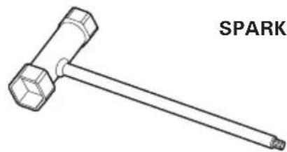
SPARK PLUG WRENCH
4 mm HEXAGON WRENCH

TOOL BAG
(UMC425U, UMC435U only)
1. Engine oil change
CAUTION:
If the engine has been running, the engine, muffler and the engine oil are very hot and they remain hot for a while after stopping the engine. To protect you from burn, wait until they cool down before starting the oil change.
NOTE:
Drain the oil while the engine is still warm to assure rapid and complete draining.
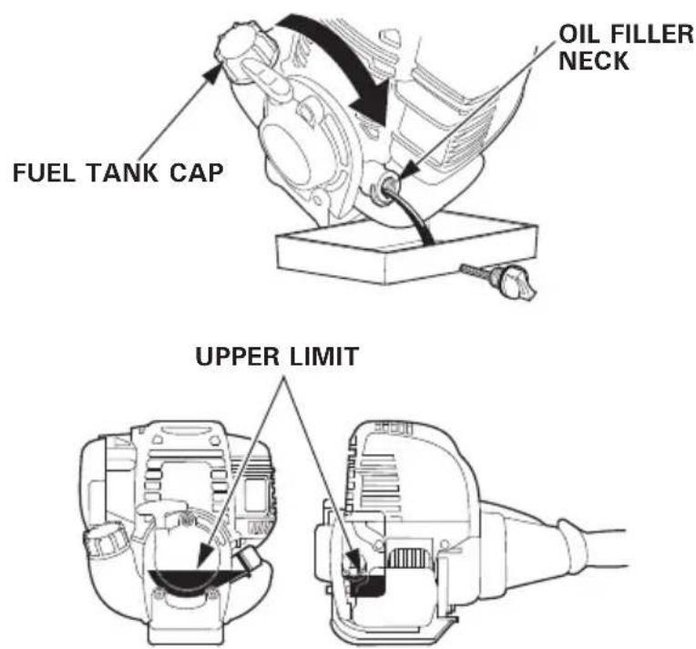
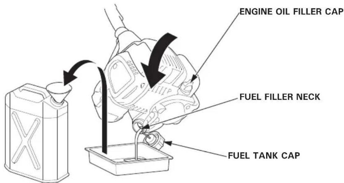
- Check the fuel tank cap is tightened.
- Remove the oil filler cap and drain the oil into the oil container by tipping the engine toward the oil filler neck.
- Refill with the recommended oil (see page 20) and check the oil level (see page 19).
4.Reinstall the oil filler cap securely.
ENGINE OIL CAPACITY
UMC425E, UMC425U: 0.08 L (0.08 US qt, 0.07 Imp qt)
UMC435E, UMC435U: 0.10 L (0.11 US qt, 0.09 Imp qt)
Wash your hands with soap and water after handling used oil.
NOTE:
Please dispose of used motor oil in a manner that is compatible with the environment. We suggest you take it in a sealed container to your local service station for reclamation. Do not throw it in the trash or pour it on the ground.
2.Air cleaner service
A dirty air cleaner will restrict air flow to the carburetor. To prevent carburetor malfunction, service the air cleaner regularly. Service more frequently when operating the power head in extremely dusty areas.
WARNING
Never use gasoline or low flash point solvents for cleaning the air cleaner element. A fire or explosion could result.
CAUTION:
Never run the engine without the air cleaner. Rapid engine wear will result.
- Move the choke lever to the CLOSED (upwards) position.
- Remove the air cleaner cover by unhooking the upper tab on the top of the air cleaner cover and its two lower tabs.
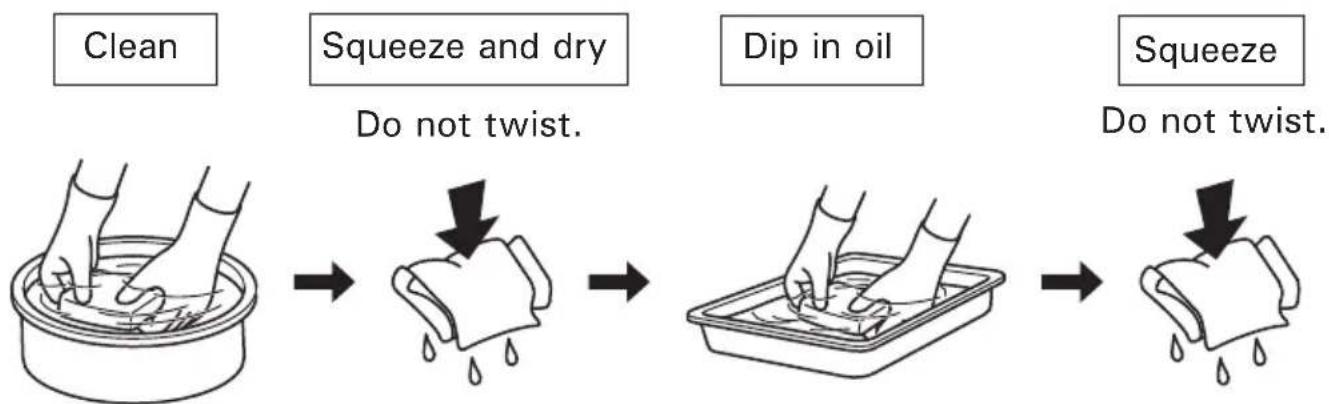
- Clean in warm soapy water, rinse and allow to dry to thoroughly. Or clean in high flash point solvent and allow to dry. Dip the element in clean engine oil and squeeze out all the excess.
The engine will smoke during initial startup if too much oil is left in the foam.
4.Reinstall the air cleaner element.
5. Reinstall the air cleaner cover by inserting the lower tabs, then insert the upper tab.
3.Spark plug service
Recommended spark plug: CMR5H (NGK)
To ensure proper engine operation, the spark plug must be properly gapped and free of deposits.
WARNING
If the engine has been running, the muffler will be very hot, be careful not to touch the muffler.
CAUTION:
Never use a spark plug of incorrect heat range.
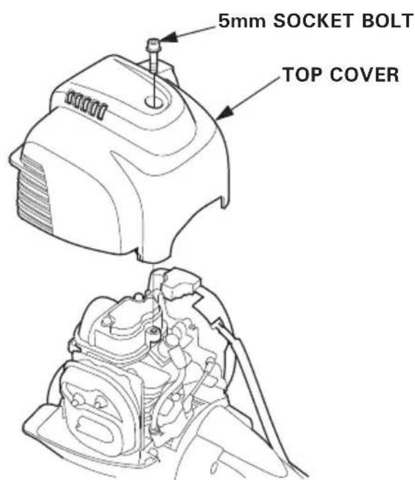
- Loosen the 5 mm hex socket bolt with a hexagon wrench, then remove the top cover.
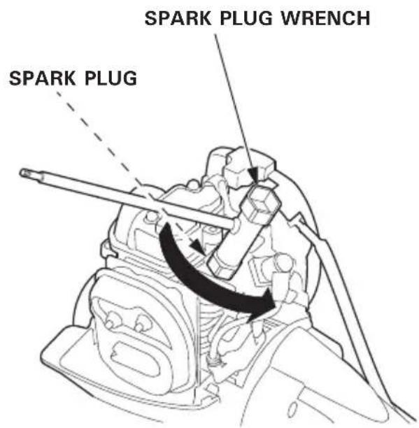
- Remove the spark plug cap and use the proper size spark plug wrench to remove the spark plug.
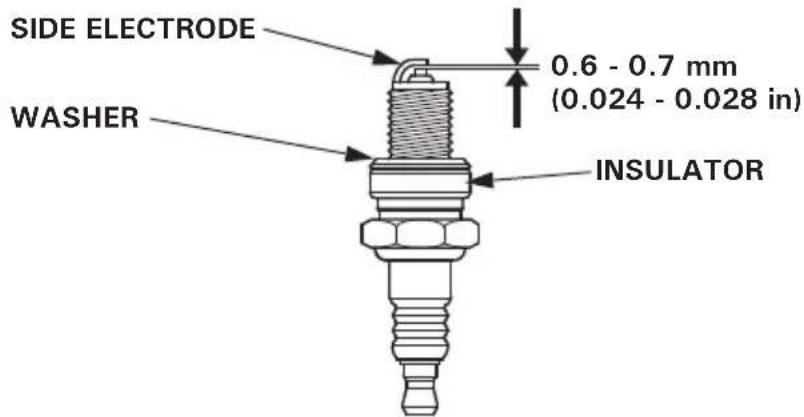
- Visually inspect the spark plug. Discard it if there is apparent wear or the insulator is cracked or chipped. Clean the spark plug with a wire brush if it is to be reused.
4.Measure the plug gap with a feeler gauge.
Correct as necessary by carefully bending the side electrode.
The gap should be: 0.6 - 0.7mm (0.024 - 0.028 in)
-
Check that the spark plug washer is in good condition and thread the spark plug in by hand to prevent cross-threading.
-
After the spark plug is seated, tighten with a spark plug wrench to compress the washer.
NOTE:
If installing a new spark plug, tighten 1/2 turn after the spark plug seats to compress the washer. If reinstalling a used spark plug, tighten 1/8 - 1/4 turn after the spark plug seats to compress the washer.
CAUTION:
The spark plug must be securely tightened. An improperly tightened plug can become very hot and possibly damage the engine.
- Attach the spark plug cap.
8.Install the top cover, and tighten the 5 mm hex socket bolt with a hexagon wrench securely.
4.Throttle cable check and adjustment
Adjust the throttle cable free play properly.
Adjustment:
- Move the choke lever to the CLOSED (upwards) position.
- Remove the air cleaner cover by unhooking the upper tab on the top of the air cleaner cover and its two lower tabs.
3.Pull out the throttle cable lightly and turn the adjusting nut to adjust the extended length of the throttle cable at the end of the cable to 0.5 - 2.5 mm (0.02 - 0.1 in). (Take care not to damage the throttle cable.)
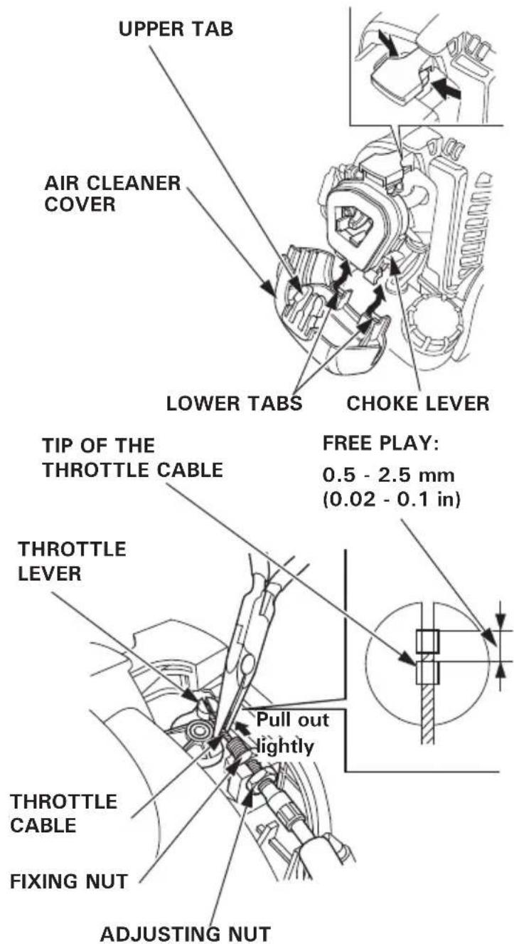
- Tighten the throttle cable fixing nut securely.
- Operate the throttle system several times and check it has the free play (i.e. throttle lever does not move while operating the throttle trigger).
After adjustment, check the throttle trigger for smooth operation.
Consult your authorized Honda dealer if necessary.
- Reinstall the air cleaner cover by inserting the lower tabs, then insert the upper tab.
CAUTION:
- After removing the air cleaner cover, reinstall the air cleaner cover securely.
Failure to tighten the cover securely may cause the cover to come out of position by vibration or some sort of engine malfunction.
- Operating the engine without the air cleaner or improperly installed air cleaner will allow dirt to enter the inside of the engine, causing adverse effect to the engine.
5. Engine cooling fin inspection
Inspect the cooling fin visually through the cover. If there are dry grass, leaves and mud clogged, consult your authorized Honda dealer for cleaning it.
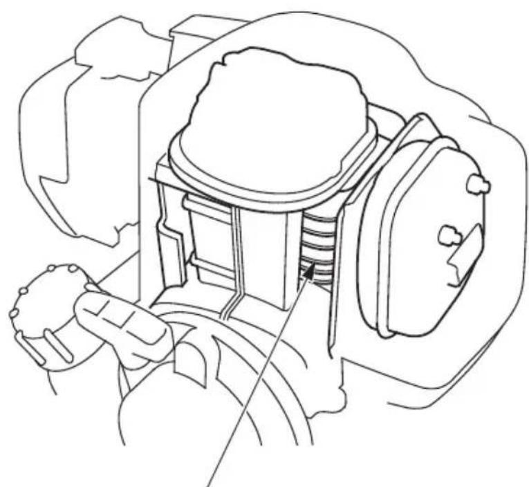
COOLING FINS
(Inside the top cover)
6.Fuel filter service/Fuel tank cleaning
Note that the clogged fuel filter can cause poor engine performance.
Water and dust, dirt or foreign material in the fuel tank cause a poor engine performance.
WARNING
Gasoline is extremely flammable and is explosive under certain conditions. You can be burned or seriously injured when handling fuel. Observe the following when servicing the fuel filter and cleaning the fuel tank.
- Stop the engine.
- Inspect in a well-ventilated area.
- Keep heat, sparks, and flame away. Do not smoke.
-
Do not spill the gasoline. If you spilled the gasoline, wipe it up immediately and dispose of the cloth or shop towel you wiped the spilled gasoline in a manner that is compatible with the environment.
-
Be sure that the engine oil filler cap is tightened securely.
- Remove the fuel tank cap and drain the gasoline into the container by tipping the engine toward the fuel filler neck.
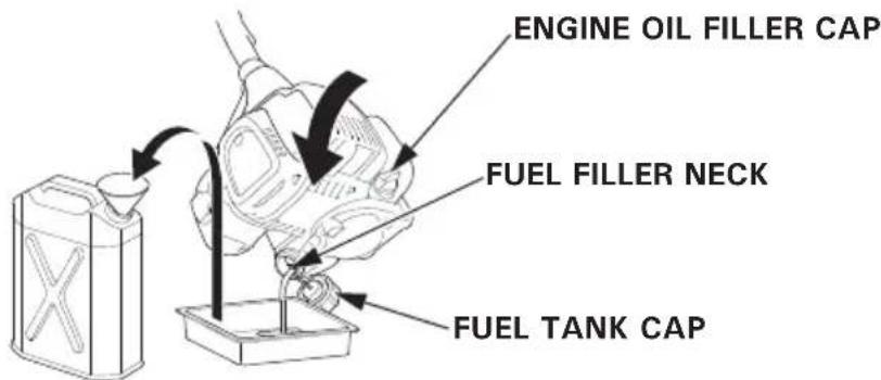
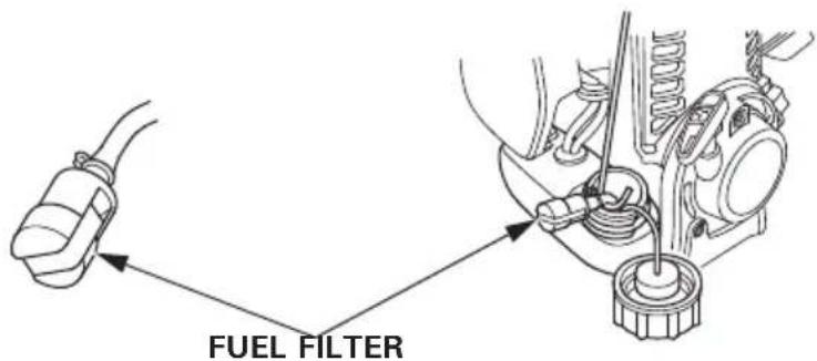
3.Pull out the fuel filter with the mechanic's wire from the fuel filler neck gently.
4. Check the fuel filter for contamination. If the fuel filter is dirty, wash it gently with nonflammable or high flash point solvent. If the fuel filter is excessively dirty, replace it.
-
Remove water and dirt stood in the fuel tank by rinsing the inside of the fuel tank with nonflammable or high flash point solvent.
-
Reinstall the fuel filter into the fuel tank and tighten the fuel tank cap securely.
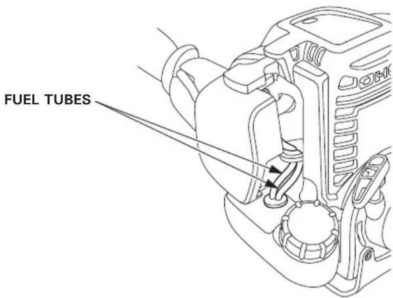
7. Fuel tube check
Check fuel tubes for cracks and any other deterioration and confirm that there is no leakage of fuel on the fuel tubes. If you notice any abnormal symptoms on the fuel tubes, contact an authorized Honda dealer.
10. TRANSPORTING
CAUTION:
To avoid severe burns or fire hazards, let the engine cool before transporting the power head.
Always turn the engine switch to the OFF position. Make sure the fuel cap is securely tightened.
Carrying the power head by hand:
Attach it to the carrying harness or hold the main pipe to carry it in a good balance.
Transporting the power head by vehicle:
Secure the power head in level and make sure that it will not move or fall down.
Proper storage preparation is essential for keeping your power head trouble free and looking good. The following steps will help to keep rust and corrosion from impairing your power head.
CAUTION:
- If the power head has been running, the engine will be very hot; allow it to cool before proceeding.
-
Place the power head on a level surface and make sure that the engine switch is in the OFF position to be certain the engine will not start accidentally.
-
Clean all exterior surfaces, touch up any damaged paint, and coat other areas that may rust with a light film of oil.
2.Drain the fuel.
WARNING
Gasoline is extremely flammable and explosive under certain conditions. Do not smoke or allow flames or sparks in the area.
a. Be sure that the engine oil filler cap is tightened securely.
b. Remove the fuel tank cap and drain the fuel into the container by tipping the engine toward the fuel filler neck.
c. Press the priming pump several times until all fuel left in the fuel return tube is returned into the fuel tank.
d. Tip the engine toward the fuel filler neck again to drain the fuel left in the fuel tank into the container.
e. Tighten the fuel tank cap securely after draining the fuel completely.
NOTE:
- Deteriorated gasoline may cause unexpected damage to your engine.
-
Gasoline should be stored in a clean container used exclusively for gasoline.
Gasoline should be stored in a cool and well ventilated place. -
Change the engine oil (see page 43).
4.Clean the air cleaner (see pages 45, 46). - Remove the top cover and remove the spark plug and pour about a tablespoon of clean engine oil into the cylinder.
- Crank the engine several revolutions to distribute the oil, then reinstall the spark plug. Pull the starter grip slowly until resistance is felt. Reinstall the top cover.
- Move the choke lever to the CLOSED position (see page 35).
8.Cover the power head and store in a dry, dust-free area.
When the engine will not start:
1.Is the engine switch in the ON position?
2.Is there fuel in the fuel tank (see page 21)?
WARNING
Gasoline is extremely flammable and explosive under certain conditions. Do not smoke or allow flames or sparks in the area.
- Is gasoline reaching the carburetor?
To check, press the priming pump several times (see page 35).
4.Is the spark plug in good condition?
Clean, readjust gap and dry the spark plug. Replace it if necessary (see page 47).
5.If the engine still does not start, take the power head to an authorized Honda dealer.
13. SPECIFICATIONS
| MODEL UMC425E | UMC435E | |
| Description code HACT HADT | ||
| MODEL UMC425U | UMC435U | |
| Description code HAET HAFT |
Frame
| MODEL UMC425E | UMC425U | UMC435E UMC435U |
| Handle type Loop | ||
| Clutch type Centrifugal clutch | ||
| Overall length 1,135 mm (44.7 in) 1,145 mm (45.1 in) | ||
| Overall width 315 mm (12.4 in) | 320 mm (12.6 in) | |
| Overall height | 245 mm (9.6 in) | 255 mm (10.0 in) |
| Dry mass (weight) | 5.1 kg (11.2 lbs) | 6.0 kg (13.2 lbs) |
NOTE:
Specifications may vary according to the types, and are subject to change without notice.
Engine
| MODEL UMC425E | UMC425U | |
| Engine model GX25T | ||
| Engine description code GCALT | ||
| Engine type 4-stroke, overhead cam, 1 cylinder | ||
| Displacement | 25.0 cm³ (1.5 cu-in) | |
| Bore and Stroke 35.0 × 26.0 mm (1.4 × 1.0 in) | ||
| Engine Net power (in accordance with SAE J1349*) | 0.72 kW (1.0 ps)/7,000 rpm | |
| Engine max. Net torque (in accordance with SAE J1349*) | 1.0 N·m (0.10 kgf·m, 0.74 lbf·ft)/5,000 rpm | |
| Idle speed 3,100 ± 200 rpm | ||
| Maximum corresponding spindle speed | MIN. 10,000 rpm | |
| Cooling system Forced air | ||
| Ignition system Transistor magneto | ||
| Oil capacity | 0.08 L (0.08 US qt, 0.07 Imp qt) | |
| Fuel tank capacity | 0.58 L (0.153 US gal, 0.128 Imp gal) | |
| Spark plug | CMR5H (NGK) | |
- The power rating of the engine indicated in this document is the net power output tested on a production engine for the engine model and measured in accordance with SAE J1349 at 7,000 rpm (Engine Net Power) and at 5,000 rpm (Engine Max. Net Torque). Mass production engines may vary from this value.
Actual power output for the engine installed in the final machine will vary depending on numerous factors, including the operating speed of the engine in application, environmental conditions, maintenance, and other variables.
NOTE:
Specifications may vary according to the types, and are subject to change without notice.
Engine
| MODEL UMC435E | UMC435U | |
| Engine model GX35T | ||
| Engine description code GCAMT | ||
| Engine type 4-stroke, overhead cam, 1 cylinder | ||
| Displacement | 35.8 cm³ (2.18 cu-in) | |
| Bore and Stroke 39.0 × 30.0 mm (1.5 × 1.2 in) | ||
| Engine Net power (in accordance with SAE J1349*) | 1.0 kW (1.4 ps)/7,000 rpm | |
| Engine max. Net torque (in accordance with SAE J1349*) | 1.6 N·m (0.16 kgf·m, 1.2 lbf·ft)/5,500 rpm | |
| Idle speed 3,100 ± 200 rpm | ||
| Maximum corresponding spindle speed | MIN. 10,000 rpm | |
| Cooling system Forced air | ||
| Ignition system Transistor magneto | ||
| Oil capacity | 0.10 L (0.11 US qt, 0.09 Imp qt) | |
| Fuel tank capacity | 0.63 L (0.166 US gal, 0.139 Imp gal) | |
| Spark plug | CMR5H (NGK) | |
- The power rating of the engine indicated in this document is the net power output tested on a production engine for the engine model and measured in accordance with SAE J1349 at 7,000 rpm (Engine Net Power) and at 5,500 rpm (Engine Max. Net Torque). Mass production engines may vary from this value.
Actual power output for the engine installed in the final machine will vary depending on numerous factors, including the operating speed of the engine in application, environmental conditions, maintenance, and other variables.
NOTE:
Specifications may vary according to the types, and are subject to change without notice.
Noise and vibration (For european model)
| MODEL UMC425E | |||
| ATTACHMENT Brush cutter Grass trimmer | |||
| Sound pressure level at operator's ears EN ISO 22868: 2011 Uncertainty 1 dB (A) 1 dB (A) | 92 dB (A) 97 dB (A) | ||
| Measured sound power level (2000/14/EC, 2005/88/EC) Uncertainty 1 dB (A) 1 dB (A) | 102 dB (A) 111 dB (A) | ||
| Guaranteed sound power level (2000/14/EC, 2005/88/EC) | 112 dB (A) | 112 dB (A) | |
| Vibration level at hand arm (EN ISO 22867: 2011) | Fr. | 4.7 m/s2 | 5.8 m/s2 |
| Rr. | 6.5 m/s2 | 5.8 m/s2 | |
| Uncertainty (EN 12096: 1997 Annex D) | Fr. | 2.4 m/s2 | 2.3 m/s2 |
| Rr. | 2.6 m/s2 | 2.3 m/s2 | |
| MODEL UMC425E | ||||
| ATTACHMENT | Pruner | Blower | ||
| Standard | Extension | |||
| Sound pressure level at operator's ears EN ISO 22868: 2011 | 90 dB (A) | 93 dB (A) | ||
| Uncertainty | 1 dB (A) | 1 dB (A) | ||
| Measured sound power level (2000/14/EC, 2005/88/EC) | 104 dB (A) | 105 dB (A) | ||
| Uncertainty | 1dB (A) 1 dB (A) | |||
| Guaranteed sound power level (2000/14/EC, 2005/88/EC) | 107 dB (A) | 107 dB (A) | ||
| Vibration level at hand arm (EN ISO 22867: 2011) | Fr. | 4.4 m/s2 | 4.1 m/s2 | 5.0 m/s2 |
| Rr. | 4.4 m/s2 | 6.5 m/s2 | 5.0 m/s2 | |
| Uncertainty (EN 12096: 1997 Annex D) | Fr. | 2.2 m/s2 | 2.0 m/s2 | 2.5 m/s2 |
| Rr. | 2.2 m/s2 | 2.6 m/s2 | 2.5 m/s2 | |
NOTE:
Specifications may vary according to the types, and are subject to change without notice.
Noise and vibration (For european model)
| MODEL UMC425E | ||||
| ATTACHMENT Hedge trimmer | ||||
| Short Long Extension Long | ||||
| Sound pressure level at operator's ears EN ISO 22868: 2011 | 90 dB (A) | |||
| Uncertainty 1 dB (A) | ||||
| Measured sound power level (2000/14/EC, 2005/88/EC) | 101 dB (A) | |||
| Uncertainty 1 dB (A) | ||||
| Guaranteed sound power level (2000/14/EC, 2005/88/EC) | 10 6 dB (A) | |||
| Vibration level at hand arm (EN ISO 22867: 2011) | Fr. | 5.9 m/s2 | 7.0 m/s2 | 3.5 m/s2 |
| Rr. | 4.4 m/s2 | 4.5 m/s2 | 6.2 m/s2 | |
| Uncertainty (EN 12096: 1997 Annex D) | Fr. | 2.4 m/s2 | 2.8 m/s2 | 1.7 m/s2 |
| Rr. | 2.2 m/s2 | 2.3 m/s2 | 2.5 m/s2 | |
| MODEL UMC425E | |||
| ATTACHMENT Edger Cultivator | |||
| Sound pressure level at operator's ears EN ISO 22868: 2011 | 91 dB (A) 89 dB (A) | ||
| Uncertainty 1 dB (A) | 2 dB (A) | ||
| Measured sound power level (EN ISO 22868: 2011) | 102 dB (A) | 102 dB (A) | |
| Uncertainty 1 dB (A) | 2 dB (A) | ||
| Guaranteed sound power level (EN ISO 22868: 2011) | 106 dB (A) | 106 dB (A) | |
| Vibration level at hand arm (EN ISO 22867: 2011) | Fr. | 4.8 m/s2 | 3.7 m/s2 |
| Rr. | 6.2 m/s2 | 5.7 m/s2 | |
| Uncertainty (EN 12096: 1997 Annex D) | Fr. | 2.4 m/s2 | 1.9 m/s2 |
| Rr. | 2.5 m/s2 | 2.3 m/s2 | |
NOTE:
Specifications may vary according to the types, and are subject to change without notice.
Noise and vibration (For european model)
| MODEL UMC435E | |||
| ATTACHMENT Brush cutter Grass trimmer | |||
| Sound pressure level at operator's ears EN ISO 22868: 2011 Uncertainty 1 dB (A) 1 dB (A) | 92 dB (A) 97 dB (A) | ||
| Measured sound power level (2000/14/EC, 2005/88/EC) Uncertainty 1 dB (A) 1 dB (A) | 105 dB (A) 110 dB (A) | ||
| Guaranteed sound power level (2000/14/EC, 2005/88/EC) | 112 dB (A) 112 dB (A) | ||
| Vibration level at hand arm (EN ISO 22867: 2011) | Fr. | 4.9 m/s2 | 5.5 m/s2 |
| Rr. | 6.1 m/s2 | 6.8 m/s2 | |
| Uncertainty (EN 12096: 1997 Annex D) | Fr. | 2.5 m/s2 | 2.2 m/s2 |
| Rr. | 2.4 m/s2 | 2.7 m/s2 | |
| MODEL UMC435E | ||||
| ATTACHMENT | Pruner | Blower | ||
| Standard | Extension | |||
| Sound pressure level at operator's ears EN ISO 22868: 2011 | 90 dB (A) | 94 dB (A) | ||
| Uncertainty | 2 dB (Å) | 2 dB (Å) | ||
| Measured sound power level (2000/14/EC, 2005/88/EC) | 105 dB (A) | 105 dB (A) | ||
| Uncertainty | 2dB (A) 2 dB (A) | |||
| Guaranteed sound power level (2000/14/EC, 2005/88/EC) | 107 dB (A) | 107 dB (A) | ||
| Vibration level at hand arm (EN ISO 22867: 2011) | Fr. | 5.6 m/s2 | 3.0 m/s2 | 4.3 m/s2 |
| Rr. | 4.3 m/s2 | 5.7 m/s2 | 5.0 m/s2 | |
| Uncertainty (EN 12096: 1997 Annex D) | Fr. | 2.3 m/s2 | 1.5 m/s2 | 2.2 m/s2 |
| Rr. | 2.1 m/s2 | 2.3 m/s2 | 2.5 m/s2 | |
NOTE:
Specifications may vary according to the types, and are subject to change without notice.
Noise and vibration (For european model)
| MODEL UMC435E | ||||
| ATTACHMENT Hedge trimmer | ||||
| Short Long Extension Long | ||||
| Sound pressure level at operator's ears EN ISO 22868: 2011 Uncertainty 2 dB (A) | 92 dB (A) | |||
| Measured sound power level (2000/14/EC, 2005/88/EC) Uncertainty 2 dB (A) | 104 dB (A) | |||
| Guaranteed sound power level (2000/14/EC, 2005/88/EC) | 106 dB (A) | |||
| Vibration level at hand arm (EN ISO 22867: 2011) Uncertainty (EN 12096: 1997 Annex D) | Fr. | 6.9 m/s2 | 5.9 m/s2 | 3.7 m/s2 |
| Rr. | 4.2 m/s2 | 4.1 m/s2 | 5.8m/s2 | |
| Fr. | 2.8 m/s2 | 2.4 m/s2 | 1.8 m/s2 | |
| Rr. | 2.1 m/s2 | 2.1 m/s2 | 2.3 m/s2 | |
| MODEL UMC435E | |||
| ATTACHMENT Edger Cultivator | |||
| Sound pressure level at operator's ears EN ISO 22868: 2011 | 91 dB (A) 91 dB (A) | ||
| Uncertainty 1 dB (A) 2 dB (A) | |||
| Measured sound power level (EN ISO 22868: 2011) | 105 dB (A) | 104 dB (A) | |
| Uncertainty 1 dB (A) | 2 dB (A) | ||
| Guaranteed sound power level (EN ISO 22868: 2011) | 106 dB (A) | 106 dB (A) | |
| Vibration level at hand arm (EN ISO 22867: 2011) | Fr. | 6.0 m/s2 | 4.3 m/s2 |
| Rr. | 6.3 m/s2 | 6.5 m/s2 | |
| Uncertainty (EN 12096: 1997 Annex D) | Fr. | 2.4 m/s2 | 2.2 m/s2 |
| Rr. | 2.5 m/s2 | 2.6 m/s2 | |
NOTE:
Specifications may vary according to the types, and are subject to change without notice.
Noise and vibration (For australian model)
| MODEL UMC425U | ||||
| ATTACHMENT Brush cutter Grass trimmer | ||||
| Sound pressure level (Australia New South Wales standard) | 69 dB (A) 75 dB (A) | |||
| Sound pressure level at ears | (AS3575: 1995 + Amdt1:1997) | 95 dB (A) 101 dB (A) | ||
| Vibration level Fr. | 8 m/s2 | 10 m/s2 | ||
| Rr. | 12 m/s2 | 10 m/s2 | ||
| MODEL UMC425U | ||
| ATTACHMENT | Pruner | Blower |
| Sound pressure level (Australia New South Wales standard) | 72 dB (A) | 77 dB (A) |
| MODEL UMC425U | ||
| ATTACHMENT | Hedge trimmer | Edger |
| Sound pressure level (Australia New South Wales standard) | 70 dB (A) | 70 dB (A) |
| MODEL UMC425U | |
| ATTACHMENT | Cultivator |
| Sound pressure level (Australia New South Wales standard) | 69 dB (A) |
NOTE:
Specifications may vary according to the types, and are subject to change without notice.
Noise and vibration (For australian model)
| MODEL UMC435U | ||||
| ATTACHMENT Brush cutter Grass trimmer | ||||
| Sound pressure level (Australia New South Wales standard) | 72 dB (A) 77 dB (A) | |||
| Sound pressure level at ears | (AS3575: 1995 + Amdt1:1997) | 96 dB (A) 101 dB (A) | ||
| Vibration level Fr. | 9 m/s2 | 9 m/s2 | ||
| Rr. | 11 m/2 | 12 m/s2 | ||
| MODEL UMC435U | ||
| ATTACHMENT | Pruner | Blower |
| Sound pressure level (Australia New South Wales standard) | 75 dB (A) | 77 dB (A) |
| MODEL UMC435U | ||
| ATTACHMENT | Hedge trimmer | Edger |
| Sound pressure level (Australia New South Wales standard) | 73 dB (A) | 72 dB (A) |
| MODEL UMC435U | |
| ATTACHMENT | Cultivator |
| Sound pressure level (Australia New South Wales standard) | 72 dB (A) |
NOTE:
Specifications may vary according to the types, and are subject to change without notice.
MANUEL DE L'UTILISATEUR
Notice originale
- Masque anti-poussières
For further information, please contact Honda Customer Information Centre at the following address or telephone number:
(Estonia/Latvia/Lithuania)
Honda Motor Europe Ltd.
Estonian Branch
Tulika 15/17
10613 Tallinn
Tel. +3726801300
Fax: +372 6801 301

honda.baltic@honda-eu.com.
BELGIUM
Honda Belgium
Doornveld 180-184
1731 Zellik
TeI. +3226201000
Fax: +32 2620 10 01
http://www.honda.be

BH_PE@HONDA-EU.COM
BULGARIA
Kirov Ltd.
49 Tsaritsa Yoana blvd 1324 Sofia
Tel. : +359 2 93 30 892
Fax: +359 2 93 30 814
http://www.kirov.net

honda@kirov.net
CROATIA
Hongoldonia d.o.o.
Vrbaska 1c
31000 Osijek
Tel. +38531320420
Fax:+38531320429
http://www.hongoldonia.hr

prodaja@hongoldonia.hr
CYPRUS
Alexander Dimitriou & Sons Ltd.
162, Yiannos Kranidiotis
Avenue
2235 Latsia, Nicosia
Tel. +357 22715300
Fax: +357 22 715 400
CZECH REPUBLIC
BG Technik cs, a.s.
U Zavodiste 251/8
15900 Prague 5 - Velka Chuchle
Tel. +420283870850
Fax: +420 2667 111 45
http://www.honda-stroje.cz
DENMARK
TIMA A/S
Tarnfalkvej 16, 2650 Hvidovre
Te1.:+4536342550
Fax: +45 36 77 16 30
http://www.hondapower.dk
FINLAND
OY Brandt AB.
M50 Business Park, Ballmount
Dublin 12
Tel.:+35314381900
Fax: +353 14607851
http://www.hondaireland.ie
Service@hondaireland.ie
ITALY
The Associated Motors
Company Ltd.
New Street in San Gwakkin Road
Afd, Power Equipment
Capronilaan 1
1119 NN Schiphol-Rijk
Tel. +31 2070000
Fax: +31 20 7070001
http://www.honda.nl
NORWAY
Berema AS
P.O.Box 454
1401 Ski
Te1.:+4764860500
Fax: +47 64 86 05 49
http://www.berema.no
Berema@berema.no
POLAND
Aries Power Equipment Sp. z o.o.
ul. Wroclawska 25
01-493 Warszawa
TeI.:+48(22)8614301
Fax: +48 (22) 861 4302
http://www.ariespower.pl
1, Pridirizhnaya Street, Sharapovo
settlement, Naro-Fominsky district,
Moscow Region, 143350 Russia
Tel.: +7 (495) 745 20-80
Fax: +7 (495) 745 2081
http://www.honda.co.ru
回 postoffice@honda.co.ru
SERBIA & MONTENEGRO
BPP Group d.o.o
Generala Horvatovica 68
11000 Belgrade
Tel.: +381 11 3820 295
Fax: +381 11 3820 296
http://www.hondasrbija.co.rs

honda@bazis.co.rs
SLOVAK REPUBLIC
Honda Slovakia, spel. s r.o.
Prievozká 6
821 09 Bratislava
Tel.:+421 232131112
Fax: +421 232131111
http://www.honda.sk
SLOVENIA
AS Domzale Moto Center D.O.O.
Blatnica 3A
1236 Trzin
Tel.: +386 1562 22 62
Fax: +386 1562 37 05
www.honda-as.com

Las Palmas province (Canary Islands)
Greens Power Products, S.L.
Poligono Industrial Congost -
Tenerife province (Canary Islands)
Honda (UK) Power Equipment
470 London Road
Slough - Berkshire, SL3 8QY
Tel. +44 (0)845 200 8000
http://www.honda.co.uk
AUSTRALIA
Honda Australia Motorcycle and
Power Equipment Pty. Ltd
1954-1956 Hume Highway
Campbellfield Victoria 3061
Tel.: (03) 9270 1111
Fax: (03) 9270 1133
CHILE
Honda Motor De Chile S.A
San Ignacio 031 Quilicura
Cod. Postal 8720018-Santiago
Tel.: +56 2 2709800
Fax: +56 2 7386511
http://www.honda.cl

contacto@honda.cl
CANADA
Honda Canada Inc.
180 Honda boulevard
Markham, ON L6C OH9
Tel.: 1-888-946-6329
Fax:1-887-939-0909
"EC Declaration of Conformity" CONTENT OUTLINE "CE-Déclaration de conformité" DESCRIPTION DE TABLE DES MATIERES "EU-Konformitätserklärung" INHALTSÜBERSICHT DESCRIPCION GENERAL DEL CONTENIDO DE LA "Declaración de Conformidad CE" DESCrizIONE DEL CONTENO DELLA "Dichiarazione CE di Conformità"
EC Declaration of Conformity
-
The undersigned, Piet Renneboog, on behalf of the authorized representative, herewith declares that the machinery described below fulfils all the relevant provisions of:
-
Directive 2006/42/EC on machinery
-
Directive 2004/108/EC on electromagnetic compatibility
-
Description of the machinery
a) Generic denomination: Power head
b) Function: drive system for attachments
| c) Commercial name d) Type e) Serial number | ||
| *1 | *1 | |
- Manufacturer
Thai Honda Manufacturing Co., Ltd.
410 Ladkrabang Industrial Estate
Lamplatue, Ladkrabang, Bangkok
10520 Thailand
- Authorized representative
Honda Motor Europe Ltd. Aalst Office
| 5. References to harmonized standards | 6. Other standards or specifications |
| EN ISO 12100:2010 | - |
- The described Honda power head can only be used in combination with the authorized attachments.
| a) Commercial name | |||
| SSBC | SSBL | SSCL | SSET |
| SSHH | SSPP | SSES | |
- Done at:
- Date:
Aalst, BELGIUM
Piet Renneboog
Homologation Manager
Honda Motor Europe, Ltd., Aalst Office
- WARNING
- Disposal
- To ensure safe operation
- Operator Responsibility
- Child Safety
- Fire and Burn Hazard
- Carbon Monoxide Poisoning Hazard
- CE mark and noise label locations
- For European model:
- For Australian model:
- Engine switch
- Priming pump
- Choke lever
- Starter grip
- 5.Throttle trigger
- NOTE:
- Throttle trigger interlock:
- 6.Joint
- 7.Quick-release latch
- CAUTION:
- ENGINE OIL CAPACITY
- Check the fuel level
- Gasolines containing alcohol
- Check the air cleaner
- Check the throttle cable free play
- Adjustment of the carrying harness
- Check the quick-release latch
- Attachment installation/removal
- Check the joint area :
- Installation:
- Removal:
- Check all bolts and nuts
- Carburetor Modification for High Altitude Operation.
- OPERATION
- Maintenance schedule
- Tool kit
- Engine oil change
- 2.Air cleaner service
- 3.Spark plug service
- 4.Throttle cable check and adjustment
- Adjustment:
- Engine cooling fin inspection
- 6.Fuel filter service/Fuel tank cleaning
- Fuel tube check
- TRANSPORTING
- When the engine will not start:
- SPECIFICATIONS
- MANUEL DE L'UTILISATEUR
- (Estonia/Latvia/Lithuania)
- BELGIUM
- BULGARIA
- CROATIA
- CYPRUS
- CZECH REPUBLIC
- DENMARK
- FINLAND
- ITALY
- NORWAY
- POLAND
- SERBIA & MONTENEGRO
- SLOVAK REPUBLIC
- SLOVENIA
- Las Palmas province (Canary Islands)
- Tenerife province (Canary Islands)
- AUSTRALIA
- CHILE
- CANADA
- "EC Declaration of Conformity" CONTENT OUTLINE "CE-Déclaration de conformité" DESCRIPTION DE TABLE DES MATIERES "EU-Konformitätserklärung" INHALTSÜBERSICHT DESCRIPCION GENERAL DEL CONTENIDO DE LA "Declaración de Conformidad CE" DESCrizIONE DEL CONTENO DELLA "Dichiarazione CE di Conformità"
- EC Declaration of Conformity
Brand : Honda
Model : UMC435
Category : Multitools