
CMXGZBF7124533 - Sprayer Craftsman - Free user manual and instructions
Find the device manual for free CMXGZBF7124533 Craftsman in PDF.
| Product Type | Tow-Behind Sprayer for Tractor |
| Brand | Craftsman |
| Model | CMXGZBF7124533 |
| Tank Capacity | 25 gallons (approx. 95 liters) |
| Power Supply | 12 V DC (tractor battery) |
| Maximum Pressure | 60 psi (4.1 bar) |
| Pump Type | Electric pump with pressure switch |
| Spray Width (boom) | Approx. 203 cm (80 in) |
| Recommended Boom Height | 35 cm (14 in) above ground |
| Nozzles | Adjustable downward-facing nozzles |
| Spray Gun | Adjustable nozzle (stream to mist) |
| Tank Material | Chemical-resistant plastic |
| Assembly | Requires assembly (tools not included) |
| Hitch | For tractor hitch (not included) |
| Warranty | 1 year (material and workmanship defects) |
| Maintenance | Clean after each use, drain, winterize with antifreeze |
| Wheel Lubrication | Annually (a few drops of oil on hubs) |
| Required Safety Equipment | Safety glasses, gloves, and protective clothing |
| Country of Manufacture | USA |
| Customer Service | 1-888-331-4569 (U.S. and Canada) |
Frequently Asked Questions - CMXGZBF7124533 Craftsman
User questions about CMXGZBF7124533 Craftsman
0 question about this device. Answer the ones you know or ask your own.
Ask a new question about this device
Download the instructions for your Sprayer in PDF format for free! Find your manual CMXGZBF7124533 - Craftsman and take your electronic device back in hand. On this page are published all the documents necessary for the use of your device. CMXGZBF7124533 by Craftsman.
USER MANUAL CMXGZBF7124533 Craftsman
English (original instructions) 1
Definitions: Safety Alert Symbols and Words
This instruction manual uses the following safety alert symbols and words to alert you to hazardous situations and your risk of personal injury or property damage.
DANGER: Indicates an imminently hazardous situation which, if not avoided, will result in death or serious injury.
W: NING: Indicates a potentially hazardous situation which, if not avoided, could result in death or serious injury.
CAITION: Indicates a potentially hazardous situation which, if not avoided, may result in minor or moderate injury.
(Land without word) Indicates a safety related message.
NOTICE: Indicates a practice not related to personal injury which, if not avoided, may result in property damage.
SAFETYWARNINGS
WARNING: Read all safety warnings, instructions, illustrations and specifications provided with this tool. Failure to follow all instructions listed below may result in fire and/or serious injury.
SAVE ALL WARNING AND INSTRUCTIONS FOR FUTURE REFERENCE
SafetyWarnings
a) Read this owners manual carefully before attempting to assemble or operate this sprayer.
b) Read your vehicle owners manual for operating and safety rules before using this equipment.
c) Never allow children to operate this sprayer, and do not allow adults to operate without proper instructions.
d) Do not allow anyone to ride on or sit on this sprayer
e) Do not allow passengers on the towing vehicle.
f) Keep the area of operation clear of all persons, particularly small children. Also keep area clear of pets.
g) Read the chemical label carefully for instructions and caution notes on handling and mixing of chemicals.
h) Wear eye and hand protection and wear protective clothing when handling and applying lawn chemicals.
i) Do not spray on windy days.
j) Attachment of this sprayer may affect your tractor's braking and stability. Be aware of your tractor's capabilities. Refer to the safety rules in the vehicle owner's manual concerning safe operation on slopes
k) Be aware of changing conditions on slopes. STAY OFF OF STEEP SLOPES.
1) Operate at reduced speed on rough terrain, along ditches and on hillsides to prevent loss of control.
m) Follow maintenance and lubrication instructions as outlined in this manual.
WARNING: Read all safety warnings and all instructions. Failure to follow the warnings and instructions may result in damage or serious injury
WARNING: Never modify the product or any part of image or personal injury could result.

WARNING: To reduce the risk of injury, read the instruction manual.
If you have any questions or comments about this or any product, call CRAFTSMAN toll free at: 1-888-331-4569.
CARTON CONTENTS
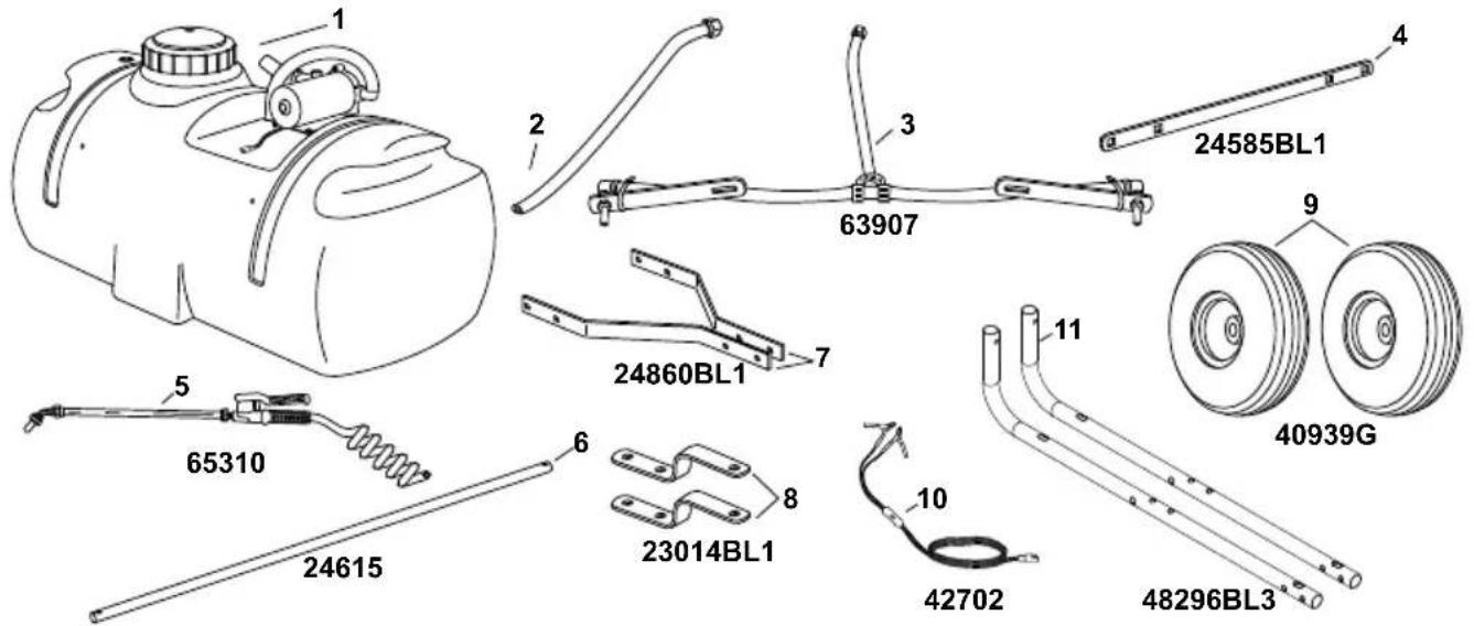
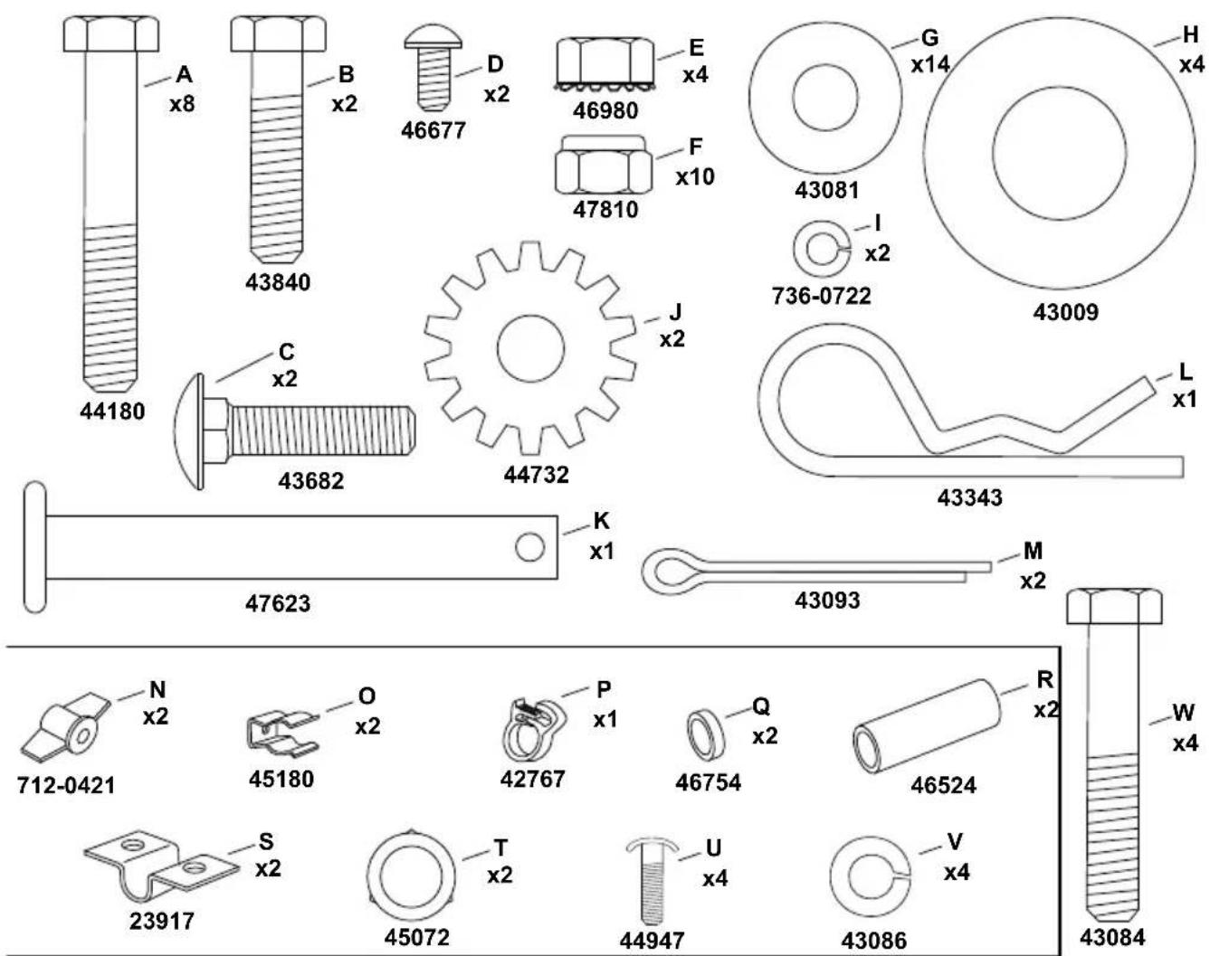
HARDWARE PACKAGE CONTENTS
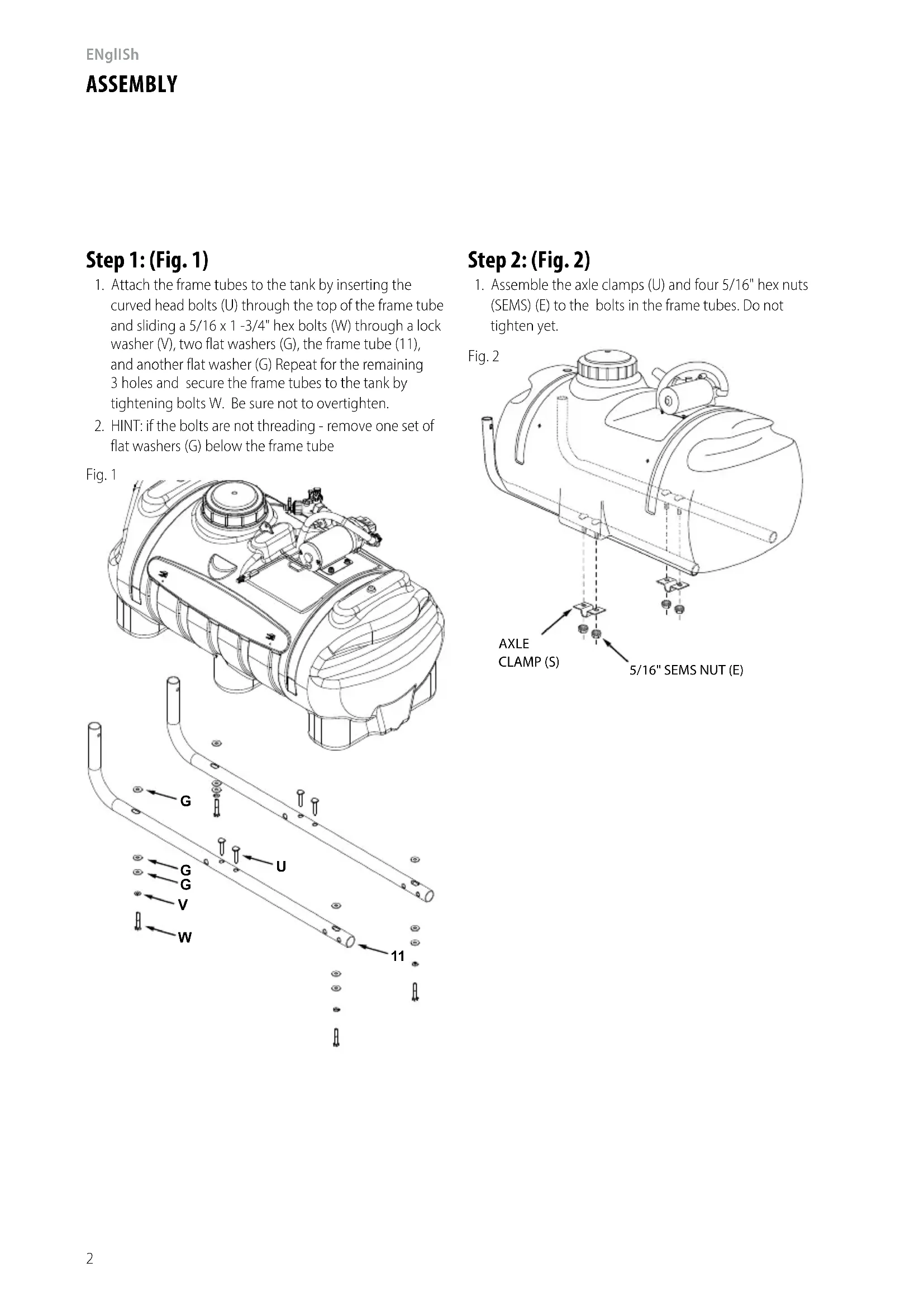
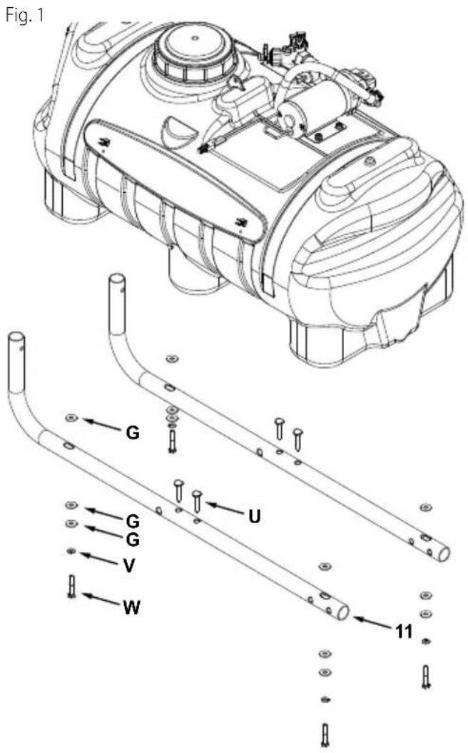
Step 1: (Fig. 1)
- Attach the frame tubes to the tank by inserting the curved head bolts (U) through the top of the frame tube and sliding a 5 / 16 × 1 - 3 / 4 hex bolts (W) through a lock washer (V), two flat washers (G), the frame tube (11), and another flat washer (G) Repeat for the remaining 3 holes and secure the frame tubes to the tank by tightening bolts W. Be sure not to overtighten.
- HINT: if the bolts are not threading - remove one set of flat washers (G) below the frame tube
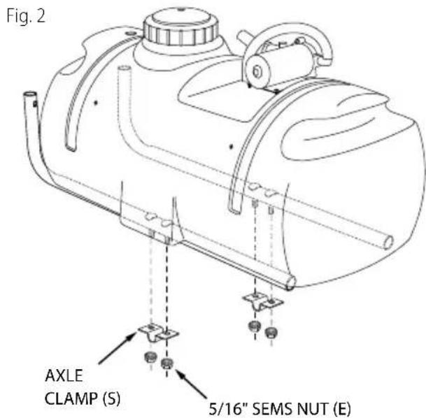
Step 2: (Fig. 2)
- Assemble the axle clamps (U) and four 5/16" hex nuts (SEMS) (E) to the bolts in the frame tubes. Do not tighten yet.
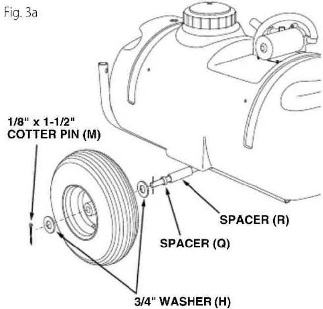
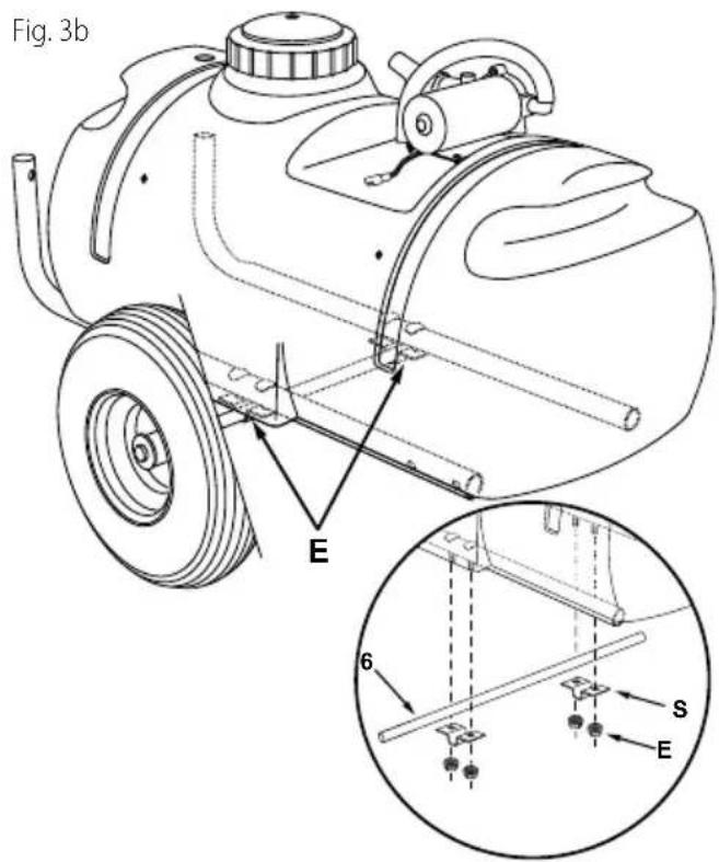
Step 3: (fig. 3a & 3b)
- Slide the axle through the two axle brackets.
- Assemble a long spacer (R), a short spacer (Q), a 3/4" washer (H), a wheel (valve stem facing out) and another 3/4" washer (H) onto the axle. Assemble a cotter pin (M) through the end of the axle. Repeat on other end.
- Tighten the four nuts which fasten the axle clamps to the frame tubes. Refer to figure 3b.r
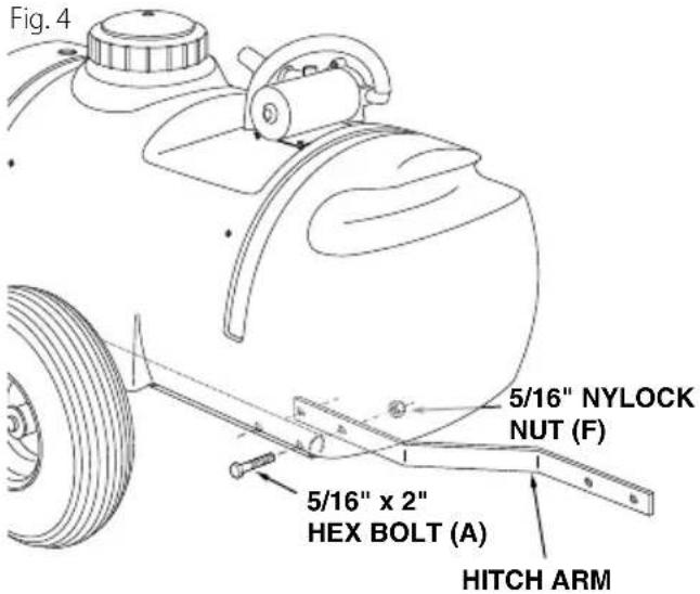
Step 4: (fig. 4)
- Assemble a hitch arm to the inside of a frame tube underneath the tank. Use two 5/16'' × 2'' hex bolts (A) and 5/16'' nylock nuts (F). Do not tighten yet. Repeat for other side.
Step 5: (fig. 5)
- Fasten the ends of the hitch arms together using two 5 / 16'' x 1-1/4" hex bolts (B) and 5 / 16'' nylock nuts (F). Do not tighten yet.
- Assemble the hitch brackets to the hitch arms using two 5 / 16'' × 2'' hex bolts (A) and 5 / 16'' nylock nuts (F). Position each bolt behind a cross bolt in the hitch arms. Do not tighten yet.
- Tighten all nuts assembled in steps 4 and 5 at this time.)

ENglISh
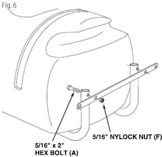
Step 6: (fig. 6)
- Assemble the boom mount bracket to the rear of the frame tubes using two 5 / 16'' × 2'' hex bolts (A) and 5 / 16'' nylock nuts (F).
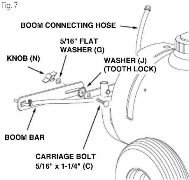
Step 7: (fig. 7)
- Assemble the boom bars to the boom mount bracket using two 5 / 16'' x 1-1/4" carriage bolts (C), tooth lock washers (J) (between the bar and bracket), 5 / 16'' flat washers (G) and knobs (N). The boom connecting hose should extend upward.
- NOTE: Make sure the nozzles are adjusted so that the openings face straight down when the boom bar is in the horizontal operating position...
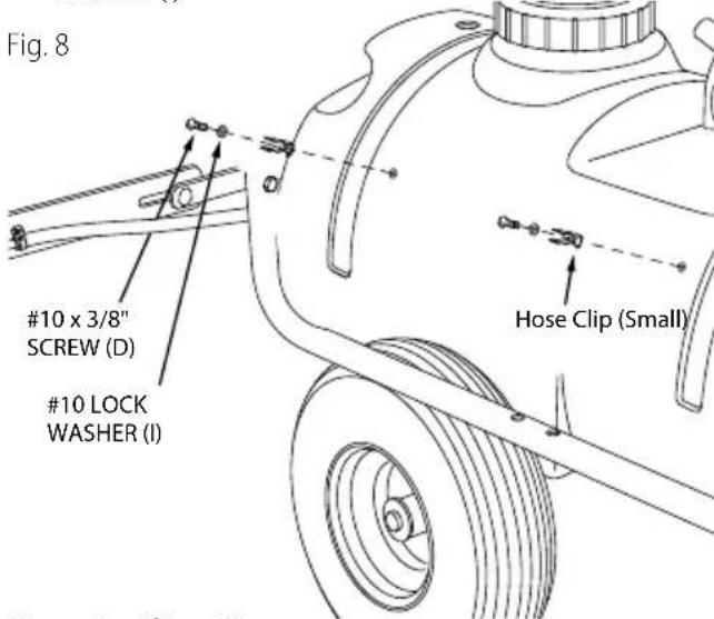
Step 8: (fig. 8)
- Assemble the small (O) spray gun clips to the side of the tank using two #10 x 1/2" screws (D) and #10 lock washers (I)
Step 9: (fig. 9)
- Insert a garden hose gasket (T) into the swivel nut on the bypass/return hose. Screw the nut onto the upper outlet of the "Y" valve fitting. Place the other end of the hose down through the hole at the rear of the tank.
- Insert a garden hose gasket (T) into the swivel nut on the boom connecting hose. Screw the nut onto the lower outlet of the "Y" valve fitting.
- Slide the coiled hose clamp (P) onto the spray gun hose. Push the hose onto the hose adapter on the side of the "T" fitting as shown in figure 9. Tighten the clamp around the hose and the adapter. Snap the spray gun into the clips on the side of the tank.)
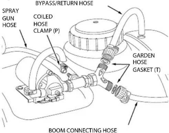
Fig.9
Step 10: (Fig. 10 & 11)
-
Attach the sprayer to the tractor hitch and connect the wiring to the tractor battery. The red wire must be connected to the positive post on the battery or to the "HOT" connection on a tractor switch or ammeter. The brown wire may be grounded or connected to the negative battery post.
-
IMPORTANT: Connect to 12 volt batteries only
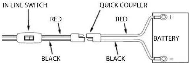
Fig. 10
CAUTION: NEVER allow negative pin on plug me in contact with positive "Hot" post on battery. Fire or explosion may result.
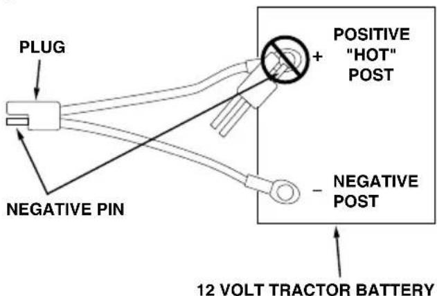
Fig. 11
OPERATION
Before Starting
It is important to test the boom and spray gun with plain water before using chemicals. This will enable you to check the sprayer for leaks and to set the spray pattern and nozzle pressure. If a leak should occur, thread tape may be used to better seal the leaking fitting.
Operator On-Off Switch
- This switch is connected in line to the wiring assembly and turns the pump motor on or off
Pump Pressure Switch
- The pump is equipped with a pressure switch. The pressure switch will temporarily turn off the electrical power to the pump at a factory predetermined high pressure point of 60 PSI. If the flow demand is very low, the pump may repeatedly reach this high pressure point and the switch will cause "cycling" (the pump cycles on and off rapidly). This is not a problem unless the pump is subject to continuous rapid cycling for long periods of time.
On-Off Adjustment of Boom Nozzles
The sprayer is equipped with a "Y" fitting containing a boom valve and a bypass valve. The boom valve turns the flow on or off to the boom nozzles. Open it completely when spraying with the boom. Close it completely if you wish to use only the spray gun..
Adjusting the Operating Pressure
- The bypass valve on the "Y" fitting controls the flow to the hose that returns fluid to the tank. The amount of flow through this hose determines the operating pressure when the boom or the spray gun is in use. Adjust the bypass valve to obtain the desired spray pattern. If misting occurs, open the bypass valve more until the misting is eliminated.
Adjusting the Spray Gun Nozzle
- Turn the nozzle on the spray gun to adjust the spray from a cone shaped fine mist to a straight stream. Control the spray gun operating pressure with the bypass valve on the "Y" fitting. Maximum spray gun pressure can be attained when the boom is shut off...
Setting the Boom for Spraying
- The correct positioning of the boom places the nozzles approximately 40 apart and 14 above the ground. This gives a spray width of approximately 80 with a slight center overlap. See figure 12.
- Slide the boom bars out to the ends of the slots.
- Swivel the boom bars until the nozzles are approximately 14" above the ground.
Make sure the nozzles are adjusted so that the openings point straight down.
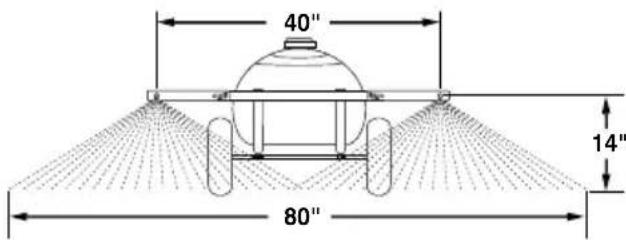
Fig. 12
ENglIsH
OPerAtiOn
using the Sprayer
- Determine the application rate (gallons per 1,000 sq. feet or gallons per acre) based on the chemical manufacturers recommendations.
- Determine the approximate square footage of the area to be sprayed and estimate the number of gallons required. This can help avoid unneeded solution left in the tank.
- Determine the appropriate speed at which to travel, based on the chosen pressure setting and the recommended application rate. Refer to the chart on this page.
-
Determine the throttle setting for attaining a specific speed by marking off 100, 200 and 300 feet intervals. The speed chart included in this manual indicates the number of seconds it takes to travel these distances. Set the throttle and, with a running start, travel the distances in the number of seconds indicated by the speed chart. Once you have determined the throttle and gear settings needed, mark the throttle location so that you can easily resume the same speed after stopping.
-
To set the operating pressure add plain water to the sprayer tank for testing. Open the boom valve completely. For maximum usable spraying pressure, close the bypass valve completely and then start opening the valve until misting stops and a normal spray pattern is obtained. Continue opening the valve if a lower spraying pressure is desired. If the spray pattern begins to break up, then the pressure is too low.
- Add the chemical solution to the tank, following the product instructions.
- Drive to the starting place for spraying. Set the boom in position for spraying. Set the throttle at the position determined in step 4. Flip the sprayer's in-line switch to the "ON" position to start spraying.
- Stay clear of flowers, shrubs and evergreen trees when spraying weed control solutions to prevent contact of the solution with these sensitive plants.
| PRESSURE (PSI) | GALLONS PER ACRE (BASED ON WATER) | ||||||
| 1 MPH 2 MPH | 3 MPH 4 MPH | 5 MPH 7.5 MPH | 10 MPH | ||||
| Maximum 58.2 | 29.1 | 19.4 | 14.5 | 11.6 | 7.8 | 5.8 | |
| PRESSURE (PSI) | GALLONS PER 1000 SQUARE FEET | ||||||
| 1 MPH 2 MPH | 3 MPH 4 MPH | 5 MPH 7.5 MPH | 10 MPH | ||||
| Maximum | 1.3 | .67 | .45 | .33 | .27 | .18 | .13 |
This chart is based on spraying at maximum pressure. Spraying at lower pressures will require traveling at slower speeds to obtain the same results.
gr0UnD SPeeD CHArt
| M.P.H. (K/H) | TIME REQUIRED IN SECONDS TO TRAVEL A DISTANCE OF: | ||
| 100 FT. (30.5 M) | 200 FT. (61 M) | 300 FT (91.5 M) | |
| 1.0 (1.6) | 68 | 136 | 205 |
| 2.0 (3.2) | 34 | 68 | 102 |
| 3.0 (4.8) | 23 | 45 | 68 |
| 4.0 (6.4) | 17 | 34 | 51 |
| 5.0 (8.0) | 14 | 27 | 41 |
| 6.0 (9.7) | 11 | 23 | 34 |
| 7.0 (11.3) | 9.7 | 19 | 29 |
| 8.0 (12.9) | 8.5 | 17 | 26 |
| 9.0 (14.5) | 7.6 | 15 | 23 |
| 10.0 (16.1) | 6.8 | 14 | 20 |
mAintenAnCe
Check For Loose Fasteners
Before each use make a thorough visual check of the sprayer for any bolts and nuts which may have loosened. Retighten any loose bolts and nuts.
Flush the Tank
- Remove any solution left in tank. Fill the sprayer part way with water, start the sprayer and allow clear water to be pumped through the plumbing system and out through the boom assembly and the handgun. Use the handgun to thoroughly wash all internal parts of the tank, the outside of the tank and the boom.
- Refill the tank about half full with plain water and a chemical neutralizer and repeat the cleaning instructions above. Flush the entire sprayer with the neutralizing agent. Follow the chemical manufacturers instructions for disposal of all wash or rinsing water.
Cleaning the Strainers
- At least once a season, clean the strainer in the end of the intake hose at the bottom of the tank. Remove the nylon swivel nut from the hose, pull out the screen and flush it with clear water.
- At least once a season, clean the strainers in the boom nozzles. Remove the nozzle, pull out the screen and flush it with clear water.
Lubrication
- Apply a few drops of oil to the wheel hubs at least once a year
Storage
- Drain all water out of the sprayer, paying special attention to the pump and handgun. These items are especially prone to damage from chemicals and freezing weather.
- The sprayer should be winterized before storage by pumping a 50-50 solution of water and R.V. antifreeze through the entire plumbing. Proper care and maintenance will prolong the life of the sprayer
- IMPORTANT: Do not allow chemicals to sit in pump for extended times of idleness. Some chemicals will damage the pump valve if allowed to soak untreated for a length of time. Always flush the pump with water after each use. Follow the procedures in the Maintenance section for flushing and disposal.
| ProBLem | caUse | correction |
| Pump motor cycles on and off rapidly. (OK) for short periods of time. | System pressure is reaching maximum setting of pump's pressure switch. | Decrease the system pressure by increasing the opening of the bypass valve. |
| Pressure too low | Bypass valve open too far. | Decrease opening of bypass valve. |
| Tank strainer dirty. Remove strainer and clean. | ||
| Pressure OK but boom spray weak | Nozzle strainers dirty. | Remove strainers and clean. |
| Boom spray pattern does not overlap enough in the middle | Nozzles set too low. Adjust boom arms.. | |
| Nozzles don't point straight down. | Rotate nozzle opening down. |
ENGLISH
Three Year Limited Warranty
CRAFTSMAN will repair or replace, without charge, any defects due to faulty materials or workmanship for three years from the date of purchase. This warranty does not cover part failure due to normal wear or tool abuse. For further detail of warranty coverage and warranty repair information, visit www.craftsman.com or call 1-888-331-4569. This warranty does not apply to accessories or damage caused where repairs have been made or attempted by others. THIS LIMITED WARRANTY IS GIVEN IN LIEU OF ALL OTHERS, INCLUDING THE IMPLIED WARRANTY OF MERCHANTABILITY AND FITNESS FOR A PARTICULAR PURPOSE, AND EXCLUDING ALL INCIDENTAL OR CONSEQUENTIAL DAMAGES. Some states do not allow limitations on how long an implied warranty lasts or the exclusion or limitation of incidental or consequential damages, so these limitations may not apply to you. This warranty gives you specific legal rights and you may have other rights which vary in certain states or provinces.
LATIN AMERICA: This warranty does not apply to products sold in Latin America. For products sold in Latin America, see country specific warranty information contained in the packaging, call the local company or see website for warranty information.
FREE WARNING LABEL REPLACEMENT: If your warning labels become illegible or are missing, call 1-888-331-4569 for a free replacement.
Register Online
Thank you for your purchase. Register your product now for:
WARRANTY SERVICE: Registering your product will help you obtain more efficient warranty service in case there is a problem with your product.
CONFIRMATION OF OWNERSHIP: In case of an insurance loss, such as fire, flood or theft, your registration of ownership will serve as your proof of purchase.
FOR YOUR SAFETY: Registering your product will allow us to contact you in the unlikely event a safety notification is required under the Federal Consumer Safety Act.
Register online at www.craftsman.com/registration
CRAFTSMAN
is a registered trademark of Stanley Black & Decker, Inc., used under license.
Product Manufactured by:
809 South Hamilton Street
Sullivan, Illinois 61951
USA
For product, service or warranty information contact us at:
- At least once a season, clean the strainer in the end of the intake hose at the bottom of the tank. Remove the nylon swivel nut from the hose, pull out the screen and flush it with clear water.
- At least once a season, clean the strainers in the boom nozzles. Remove the nozzle, pull out the screen and flush it with clear water.
Lubrification
REEMPLACEMENT Gratisuit DES ETIQUETTES
Product Manufactured by:
809 South Hamilton Street
Sullivan, Illinois 61951
USA
- DEFINITIONS: SAFETY ALERT SYMBOLS AND WORDS
- SAFETYWARNINGS
- SAVE ALL WARNING AND INSTRUCTIONS FOR FUTURE REFERENCE
- CARTON CONTENTS
- HARDWARE PACKAGE CONTENTS
- STEP 1: (FIG. 1)
- STEP 2: (FIG. 2)
- STEP 3: (FIG. 3A & 3B)
- STEP 4: (FIG. 4)
- STEP 5: (FIG. 5)
- ENGLISH
- STEP 6: (FIG. 6)
- STEP 7: (FIG. 7)
- STEP 8: (FIG. 8)
- STEP 9: (FIG. 9)
- STEP 10: (FIG. 10 & 11)
- OPERATION
- BEFORE STARTING
- OPERATOR ON-OFF SWITCH
- PUMP PRESSURE SWITCH
- ON-OFF ADJUSTMENT OF BOOM NOZZLES
- ADJUSTING THE OPERATING PRESSURE
- ADJUSTING THE SPRAY GUN NOZZLE
- SETTING THE BOOM FOR SPRAYING
- USING THE SPRAYER
- MAINTENANCE
- CHECK FOR LOOSE FASTENERS
- FLUSH THE TANK
- CLEANING THE STRAINERS
- LUBRICATION
- STORAGE
- THREE YEAR LIMITED WARRANTY
- REGISTER ONLINE
- CRAFTSMAN
- LUBRIFICATION
- REEMPLACEMENT GRATISUIT DES ETIQUETTES
Brand : Craftsman
Model : CMXGZBF7124533
Category : Sprayer