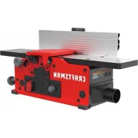
CMEW020 - Milling machine Craftsman - Free user manual and instructions
Find the device manual for free CMEW020 Craftsman in PDF.


| Product Type | Bench Jointer (Jointer Planer) |
| Brand | Craftsman |
| Model | CMEW020 |
| Maximum Cut Width | 152 mm (6 in) |
| Maximum Cut Depth | 3.2 mm (1/8 in) |
| Variable Speed | 6,000 - 11,000 RPM (12,000 - 22,000 cuts/min) |
| Motor | 120 V, 10 A, 60 Hz |
| Power Supply | Mains 120 V AC |
| Number of Blades | 2 |
| Tilting Fence | Yes, up to 45° (positive stops at 45° and 90°) |
| Cutterhead Locking Device | Yes |
| Cutterhead Guard | Yes |
| Dust Chute | Yes, with 51 mm (2 in) vacuum adapter |
| Push Blocks Included | Yes |
| Assembly Tools Included | Two hex wrenches |
| Estimated Assembly Time | 1 hour |
| Warranty | 3-year limited, 90-day money-back guarantee |
| Weight | Approximately 27 kg (60 lb) |
| Table Dimensions | Not specified in the manual |
| Cut Depth Adjustment | Yes, by knob |
Frequently Asked Questions - CMEW020 Craftsman
User questions about CMEW020 Craftsman
0 question about this device. Answer the ones you know or ask your own.
Ask a new question about this device
Download the instructions for your Milling machine in PDF format for free! Find your manual CMEW020 - Craftsman and take your electronic device back in hand. On this page are published all the documents necessary for the use of your device. CMEW020 by Craftsman.
USER MANUAL CMEW020 Craftsman
IF YOU HAVE QUESTIONS OR COMMENTS, CONTACT US.
POUR TOUTE QUESTION DU TOUT COMMENTAIRE, NOUS CONTACTER.
SI TIENE DUDAS O COMENTARIOS, CONTACTENDS.
1-888-331-4569 WWW.CRAFTSMAN.COM
English (original instructions) 1
Definitions: Safety Alert Symbols and Words
This instruction manual uses the following safety alert symbols and words to alert you to hazardous situations and your risk of personal injury or property damage.
DAGGER: Indicates an imminently hazardous situation which, if not avoided, will result in death or serious injury.
WPNING:Indicates a potentially hazardous situation which, if not avoided, could result in death or serious injury.
CAITION: Indicates a potentially hazardous situation which, if not avoided, may result in minor or moderate injury.
(Without word) Indicates a safety related message.
NOTICE: Indicates a practice not related to personal injury which, if not avoided, may result in property damage.
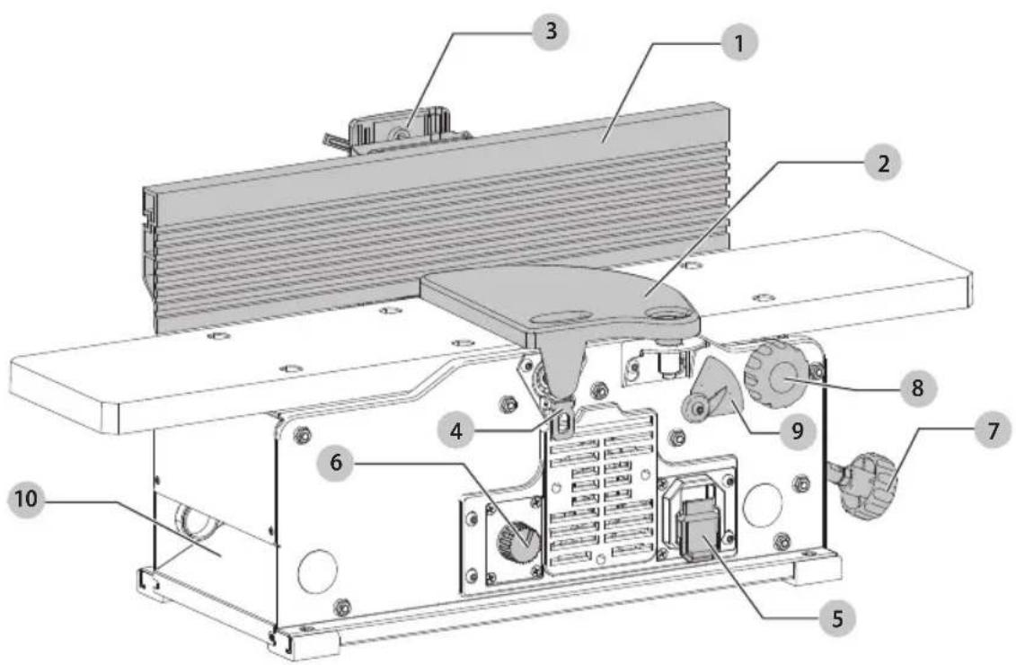
Fig. A
COMPONENTS
1 Fence
2 Cutterhead guard
3 Fence sliding bracket
4 Cutterhead lock
5 On/off switch
6 Variable speed control
7 Table height adjustment
8 Lock knob
9 Depth scale
10 Dust shoot
WARNING: Read all safety warnings and all
Instructions. Failure to follow the warnings and instructions may result in electric shock, fire and/or serious injury.
WARNING: Never modify the power tool or any part of damage or personal injury could result.

WARNING: To reduce the risk of injury, read the instruction manual.
If you have any questions or comments about this or any product, call CRAFTSMAN toll free at: 1-888-331-4569.
6" (152 mm) Variable Speed Bench Jointer CMEW020
General Safety Instructions
- KEEP GUARDS IN PLACE and in working order.
- REMOVE ADJUSTING KEYS AND WRENCHES. Form habit of checking to see that keys and adjusting wrenches are removed from tool before turning it on.
- KEEP WORK AREA CLEAN. Cluttered areas and benches invite injuries.
- DON'T USE IN DANGEROUS ENVIRONMENT. Don't use power tools in damp or wet locations, or expose them to rain. Keep work area well lighted. Always operate tool in a well-ventilated area free of combustible materials, gasoline or solvent vapors. If sparks come in contact with flammable vapors, they may ignite, causing fire or explosion.
- KEEP CHILDREN AWAY. All visitors should be kept safe distance from work area.
- MAKE WORKSHOP KID PROOF with padlocks, master switches, or by removing starter keys.
- DON'T FORCE TOOL. It will do the job better and safer at the rate for which it was designed.
- USE RIGHT TOOL. Don't force tool or attachment to do a job for which it was not designed.
- USE PROPER EXTENSION CORD. Make sure your extension cord is in good condition. When using an extension cord, be sure to use one heavy enough to carry the current your product will draw. An undersized cord will cause a drop in line voltage resulting in overheating and loss of power. The Minimum Gauge for Cord Sets table shows the correct size to use depending on cord length and nameplate ampere rating. If in doubt, use the next heavier gauge. The smaller the gauge number, the heavier the cord. When operating a power tool outside, use an outdoor extension cord marked "W-A" or "W." These cords are rated for outdoor use and reduce the risk of electric shock.
- WEAR PROPER APPAREL. Do not wear loose clothing, gloves, neckties, rings, bracelets, or other jewelry which may get caught in moving parts. Nonslip footwear is recommended. Wear protective hair covering to contain long hair. Air vents often cover moving parts and should also be avoided.
- ALWAYS USE SAFETY GLASSES. Also use face or dust mask if cutting operation is dusty. Everyday eyeglasses only have impact resistant lenses, they are not safety glasses.
- SECURE WORK. Use of clamps or a vise to hold work when practical. It's safer than using your hands and it frees both hands to operate tool.
- DON'T OVERREACH. Keep proper footing and balance at all times.
-
MAINTAIN TOOLS WITH CARE. Keep tools sharp and clean for best and safest performance. Follow instructions for lubricating and changing accessories.
-
DISCONNECT TOOLS before servicing; when changing accessories, such as blades, bits, cutters, and the like.
- REDUCE THE RISK OF UNINTENTIONAL STARTING. Make sure switch is in off position before plugging in.
- USE RECOMMENDED ACCESSORIES. Consult the instruction manual for recommended accessories. The use of improper accessories may cause risk of injury to persons.
- NEVER STAND ON TOOL. Serious injury could occur if the tool is tipped or if the cutting tool is unintentionally contacted.
- CHECK DAMAGED PARTS. Before further use of the tool, a guard or other part that is damaged should be carefully checked to determine that it will operate properly and perform its intended function—check for alignment of moving parts, binding of moving parts, breakage of parts, mounting, and any other conditions that may affect its operation. A guard or other part that is damaged should be properly repaired or replaced.
- DIRECTION OF FEED. Feed work into planer according to direction of feed arrows on top of the unit.
- NEVER LEAVE TOOL RUNNING UNATTENDED. TURN POWER OFF. Don't leave tool until it comes to a complete stop.
Additional Safety Rules for Jointers
WARNING: Failure to follow these rules may be in serious personal injury.
- Do not operate this machine until it is completely assembled and installed according to the instructions. A machine incorrectly assembled can cause serious injury.
- Obtain advice from your supervisor, instructor, or another qualified person if you are not thoroughly familiar with the operation of this machine. Knowledge is safety.
- Follow all wiring codes and recommended electrical connections to prevent shock or electrocution.
- Keep knives sharp and free from rust and pitch. Dull or rusted knives work harder and can cause kickback.
- Tighten the infeed/outfeed tables before starting the machine. Loss of control of the workpiece can cause serious injury.
- Properly secure the blades in the cutterhead before turning the power "ON". Loose blades may be thrown out at high speeds.
- Never turn the machine "ON" before clearing the table of all objects (tools, scraps of wood, etc.). Flying debris can cause serious injury.
- Never turn the machine "ON" with the workpiece contacting the cutterhead. Kickback can occur.
-
Avoid awkward operations and hand positions. A sudden slip could cause a hand to move into the cutterhead.
-
Keep arms, hands, and fingers away from the cutterhead to prevent severe injury.
- Never make cuts deeper than 1/8'' (3.2 mm) to prevent kickback.
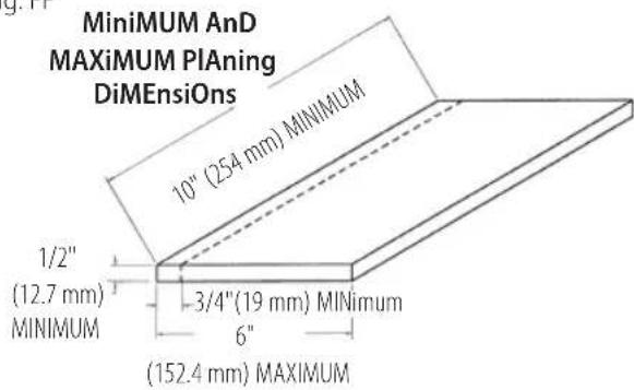
- Never joint or plane a workpiece that is shorter than 10^ (254 mm), narrower than 3 / 4^ (19 mm), or less than 1 / 2^ (12.7mm) thick. Jointing smaller workpieces can place your hand in the cutterhead causing severe injury.
- Use hold-down/push blocks for jointing or planing any workpiece lower than the fence. Jointing or planing small workpieces can result in kickback and severe injury.
- Hold the workpiece firmly against the table and fence. Loss of control of the workpiece can cause kickback and result in serious injury.
- Never perform "free-hand" operations. Use the fence to position and guide the workpiece. Loss of control of the workpiece can cause serious injury.
- Do not attempt to perform an abnormal or little-used operation without study and the use of adequate hold-down/push blocks, jigs, fixtures, stops, etc.
- Do not feed a workpiece into the outfeed end of the machine. The workpiece will be thrown out of the opposite end at high speeds.
- Do not feed a workpiece that is warped, contains knots, or is embedded with foreign objects (nails, staples, etc.) to prevent kickback.
- Maintain the proper relationship of infeed and outfeed table surfaces and cutterhead knife path. Loss of control of the workpiece can cause serious injury.
- Properly support long or wide workpieces. Loss of control of the workpiece can cause injury.
- Never perform layout, assembly, or set-up work on the table/work area when the machine is running. A sudden slip could cause a hand to move into the cutterhead. Severe injury can result.
- Remove shavings only with the power "OFF" and the cutterhead stopped to prevent serious injury.
- Turn the machine "OFF", disconnect the machine from the power source, and clean the table/work area before leaving the machine. Lock the switch in the "OFF" position to prevent unauthorized use. Someone else might accidentally start the machine and cause injury to themselves.
- Additional information regarding the safe and proper operation of power tools (i.e. a safety video) is available from the Power Tool Institute, 1300 Sumner Avenue, Cleveland, OH 44115-2851 (www.powertoolinstitute.com). Information is also available from the National Safety Council, 1121 Spring Lake Drive, Itasca, IL 60143-3201. Please refer to the American National Standards Institute ANSI 01.1 Safety Requirements for Woodworking Machines and the U.S. Department of Labor OSHA 1910.213 Regulations.
- Keep cutterhead guard in place and in working order.
Additional Safety Information
WARNING: ALWAYS use safety glasses. Everyday eyeglasses are NOT safety glasses. Also use face or dust mask if operation is dusty. ALWAYS WEAR CERTIFIED SAFETY EQUIPMENT:
ANSI Z87.1 eye protection (CAN/CSA Z94.3)
ANSI S12.6 (S3.19) hearing protection,
- NIOSH/OSHA/MSHA respiratory protection.
WARNING: Some dust created by power sanding, grinding, drilling, and other construction activities contains chemicals known to the State of California to cause cancer, birth defects or other reproductive harm. Some examples of these chemicals are:
- lead from lead-based paints,
crystalline silica from bricks and cement and other masonry products, and - arsenic and chromium from chemically-treated lumber.
Your risk from these exposures varies, depending on how often you do this type of work. To reduce your exposure to these chemicals: work in a well ventilated area, and work with approved safety equipment, such as those dust masks that are specially designed to filter out microscopic particles.
- Avoid prolonged contact with dust from power sanding, sawing, grinding, drilling, and other construction activities. Wear protective clothing and wash exposed areas with soap and water. Allowing dust to get into your mouth, eyes, or lay on the skin may promote absorption of harmful chemicals.
WARNING: Use of this tool can generate and/ or disperse dust, which may cause serious and permanent respiratory or other injury. Always use NIOSH/OSHA approved respiratory protection appropriate for the dust exposure. Direct particles away from face and body.
WARNING: Always wear proper personal hearing protection that conforms to ANSI S12.6 (S3.19) during use. Under some conditions and duration of use, noise from this product may contribute to hearing loss.
Air vents often cover moving parts and should be avoided. Loose clothes, jewelry or long hair can be caught in moving parts.
- An extension cord must have adequate wire size (AWG or American Wire Gauge) for safety. The smaller the gauge number of the wire, the greater the capacity of the cable, that is, 16 gauge has more capacity than 18 gauge. An undersized cord will cause a drop in line voltage resulting in loss of power and overheating. When using more than one extension to make up the total length, be sure each individual extension contains at least the minimum wire size. The following table shows the correct size to use depending on cord length and nameplate ampere rating. If in doubt, use the next heavier gauge. The lower the gauge number, the heavier the cord.
Minimum Gauge for Cord Sets
| Volts | Total Length of Cord in Feet(meters) | ||||
| 120 V 25 (7.6) | 50 (15.2) | 100 (30.5) | 150 (45.7) | ||
| 240 V 50 (15.2) | 100 (30.5) | 200 (61.0) | 300 (91.4) | ||
| Ampere Rating | American Wire Gauge | ||||
| More Than | Not More Than | ||||
| 0 6 18 | 16 16 14 | ||||
| 6 10 18 | 16 14 12 | ||||
| 10 12 16 | 16 14 12 | ||||
| 12 16 14 | 12 Not Recommended | ||||
Power Connections
A separate electrical circuit should be used for your machines. This circuit should not be less than #12 wire and should be protected with a 20 Amp time lag fuse.
NOTE: Time delay fuses should be marked "D" in Canada and "T" in the U.S. If an extension cord is used, use only 3-wire extension cords which have 3-prong grounding type plugs and matching receptacle which will accept the machine's plug. Before connecting the machine to the power line, make sure the switch (or switches) is in the "OFF" position and be sure that the electric current is of the same characteristics as indicated on the machine. All line connections should make good contact. Running on low voltage will damage the machine.
DANGER: Do not expose the machine to rain or locate the machine in damp locations.
Motor Specifications
Your machine is wired for 120 Volts, 60Hz alternating current. Before connecting the machine to the power source, make sure the switch is in the "OFF" position.
Grounding Instructions (Fig B, C)
DANGER: This machine must be grounded while to protect the operator from electric shock.
1. All grounded, cord-connected machines:
- In the event of a malfunction or breakdown, grounding provides a path of least resistance for electric current to reduce the risk of electric shock. This machine is equipped with an electric cord having an equipment-grounding conductor and a grounding plug. The plug must be plugged into a matching outlet that is properly installed and grounded in accordance with all local codes and ordinances.
- Do not modify the plug provided - if it will not fit the outlet, have the proper outlet installed by a qualified electrician.
- Improper connection of the equipment-grounding conductor can result in risk of electric shock. The conductor with insulation having an outer surface that is green with or without yellow stripes is
the equipment-grounding conductor. If repair or replacement of the electric cord or plug is necessary, do not connect the equipment-grounding conductor to a live terminal.
- Check with a qualified electrician or service personnel if the grounding instructions are not completely understood, or if in doubt as to whether the machine is properly grounded.
- Use only 3-wire extension cords that have 3-prong grounding type plugs and matching 3-conductor receptacles that accept the machine's plug, as shown in Fig. B.
- Repair or replace damaged or worn cord immediately.
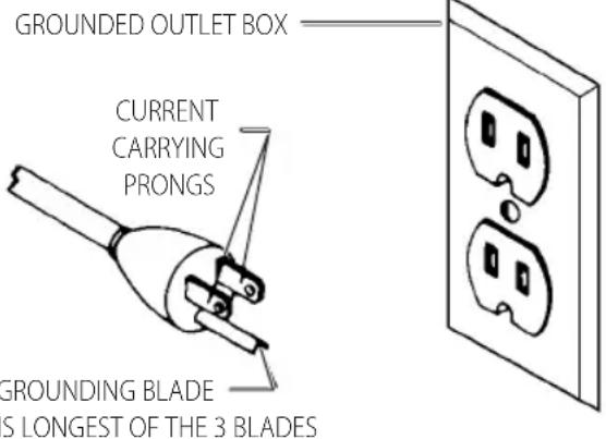
Fig. B
2. Grounded, cord-connected machines intended for use on a supply circuit having a nominal rating less than 150 Volts:
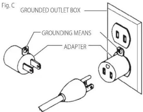
- If the machine is intended for use on a circuit that has an outlet that looks like the one illustrated in Fig. B, the machine will have a grounding plug that looks like the plug illustrated in Fig. B. A temporary adapter, which looks like the adapter illustrated in Fig. C, may be used to connect this plug to a matching 2-conductor receptacle as shown in Fig. C if a properly grounded outlet is not available. The temporary adapter should be used only until a properly grounded outlet can be installed by a qualified electrician. The green-colored rigid ear, lug, and the like, extending from the adapter must be connected to a permanent ground such as a properly grounded outlet box. Whenever the adapter is used, it must be held in place with a metal screw.
NOTE: In Canada, the use of a temporary adapter is not permitted by the Canadian Electric Code.
DANGER: In all cases, make certain that the receptacle in question is properly grounded. If you are not sure, have a qualified electrician check the receptacle.
SAVE THESE INSTRUCTIONS FOR FUTURE USE
COMPONENTS (FIG. A)
Motor
Be sure your power supply agrees with the nameplate marking. Voltage decrease of more than 10% will cause loss of power and overheating. These tools are factory tested; if this tool does not operate, check power supply.
Intended Use
The CMEW020 is a 6" (152 mm), variable-speed bench jointer intended for jointing and planing wood with a designed cutting capacity of 6" (152 mm) wide and 1/8" (3 mm) deep. Unit includes a 10 Amp, 120 Volt motor with a variable speed range of 6000 to 11000 RPM, and a cutting speed range of 12000 to 22000 CPM, a dust chute, a center-mounted fence, a two-knife cutterhead, a cutterhead guard and lock, wrenches, and push blocks.
DO nOT use under wet conditions or in presence of flammable liquids or gases.
DO NOT let children come into contact with the tool. Supervision is required when inexperienced operators use this tool.
ASSEMBLY AND ADJUSTMENTS
WARNING: To reduce the risk of serious personal injury, turn unit off and disconnect it from power source before making any adjustments or removing/installing attachments or accessories.
An accidental start-up can cause injury.
Unpacking and Cleaning
Carefully unpack the machine and all loose items from the shipping container(s). Remove the rust-preventative oil from unpainted surfaces using a soft cloth moistened with mineral spirits, paint thinner or denatured alcohol.
NOTICE: Do not use highly volatile solvents such as gasoline, naphtha, acetone or lacquer thinner for cleaning your machine.
After cleaning, cover the unpainted surfaces with a good quality household floor paste wax.
Assembly Tools Required
Two hex wrenches (supplied)
Assembly Time Estimate
Assembly for this machine takes approximately 1 hour.
Fence (Fig. D-J)
- Assemble the fence mounting bracket 11 to the jointer base using the four M6 x 1 mm x 16 mm button head screws 12.
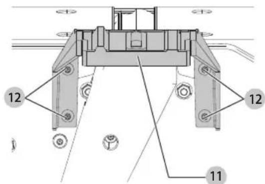
Fig. D
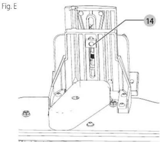
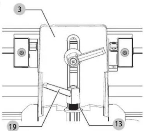
- Assemble the fence sliding bracket 3 to fence mounting bracket 11 using the lockhandle 19, M8 flat washer 13 and special nut 14.
English
Fig. F
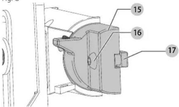
3. Insert a M6 x 1 mm x 16 mm button head screw 16 through fence tilting bracket 15 and thread a M6 x 1 square nut 17 onto threaded end of screw 16. DO NOT COM PLETE LY TIGHTEN SCREW AT THIS TIME. Assemble screw and square nut to opposite end of tilting bracket in the same manner.
Fig. G
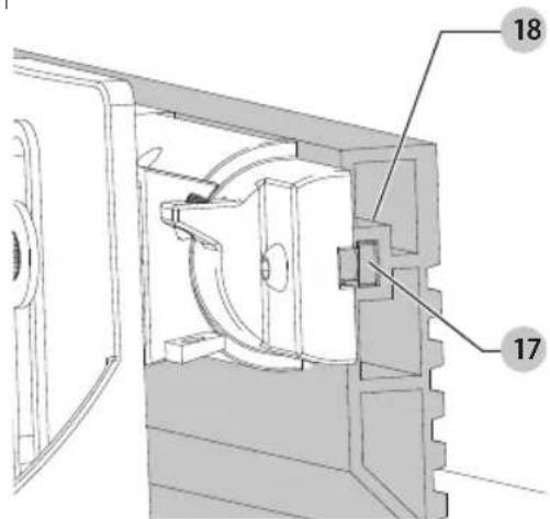
4. Slide groove of fence 18 over square nuts 17.
Fig. H
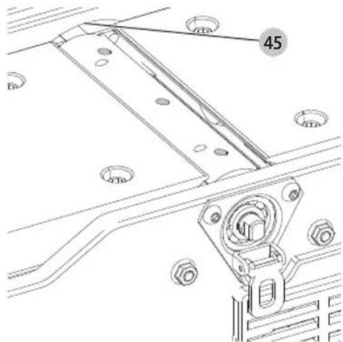
5. Position fence 1 so that rounded section 45 on bottom of fence is over cutterhead opening.
Fig.1
6. Tighten two screws 16 using included hex wrench.
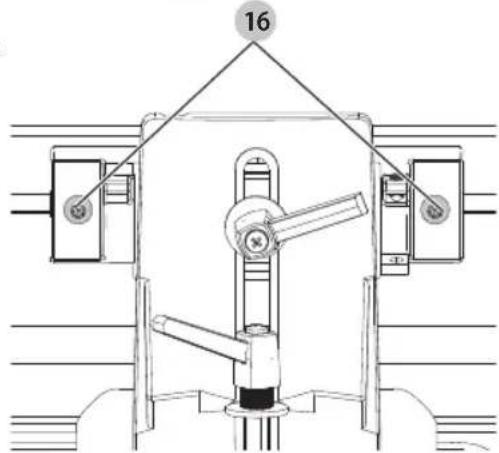
Fig. J
Cutterhead Lock (Fig. K)
Assemble cutterhead lock 4 to the front side of the jointer base, using the M6 x 1 mm x 12 mm button head screw 21. NOTE: The cutterhead lock is to be engaged with the cutterhead shaft only when setting knives. All other times, the cutterhead lock should be disengaged from the cutterhead.
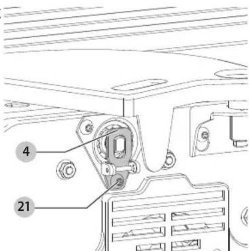
Fig. K
Fastening Jointer to Supporting Surface (Fig. M)
If during operation, there is any tendency for the jointer to tip over, slide or "walk" on the supporting surface, the jointer must be secured to the supporting surface. Four holes (two of which are shown at 22 Fig. M, are provided for this purpose.
Dust Collector Hose Adapter (Fig. L, M)
A dust collector hose adapter 23 is supplied with the jointer to help connect it to a standard 2^ (51 mm) vacuum hose. To assemble the adapter:
- Remove two screws 25. Loosen screws 26.
- Slide adapter's slots 24 under loosened screws 26
- Tighten screws 26 when adapter 23 is in proper location.
- Replace and tighten screws 25.
NOTICE: Do not install this vacuum hose adapter unless you will be using a dust collector.
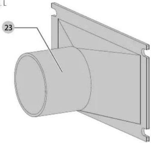
Fig. L
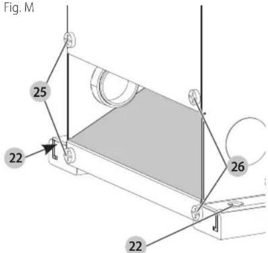
Fig. M
OPERATION
WARNING: To reduce the risk of serious personal injury, turn unit off and disconnect it from power source before making any adjustments or removing/installing attachments or accessories.
An accidental start-up can cause injury.
Stopping and Starting the Jointer (Fig. N)
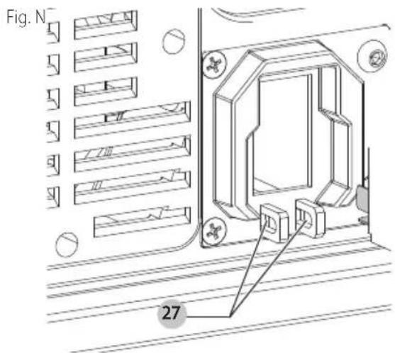
To turn the planer on, lift up the switch 5. The planer locks on automatically. To turn the tool off, press the switch down. Two holes 27 are provided in the bottom of the switch housing for locking off the planer with a padlock.
Variable Speed Control (Fig. 0)
Your jointer is supplied with variable speed control 6 that enables you to operate the machine at cutterhead speeds between 6000 and 11000 RPM. Speed indicators of 1, 2, 3, 4 and 5 are provided on the speed dial.
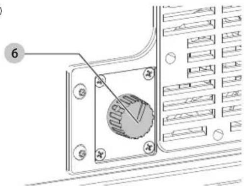
Fig. O
Speed Approximate RPI
| 16000 | |
| 27250 | |
| 38800 | |
| 49750 | |
| 511000 |
Speed Selection Chart
Use the speed selection chart to determine the proper setting for your workpiece.
English
NOTE: For convenience, make a copy of this chart and post it on or near the machine.
| sPEED sELECTiOn ChART | |||||
| CUTTING WiDTh COnTROl sETting | |||||
| FROM TO PLASTICS SOFT | WOODHARD WOOD | ||||
| inches mm inches | mm | ||||
| 0 0 1-1/2 38.1 | 1 1 1 | ||||
| 1-1/2 38.1 2-1/2 | 65.5 2 2 3 | ||||
| 2-1/2 63.5 3-1/4 | 82.5 3 3 4 | ||||
| 3-1/4 82.5 4 101.6 | -4 5 | ||||
| 4 101.6 6 152.4 | -5 5 | ||||
Depth of Cut Adjustment (Fig. P)
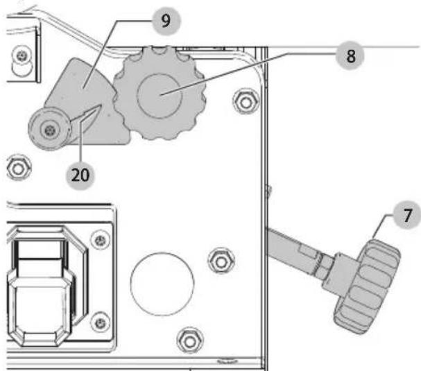
The jointer can be set to cut any depth from a very thin shaving to 1/8 (3.2 mm) deep. A dual English/Metric scale 9, and pointer 20 are provided to indicate the depth of cut. To adjust for depth of cut, loosen lock knob 8 and turn table height adjustment knob 7 clockwise to lower and count ter clock wise to raise the infeed table. Raising the infeed table decreases the depth of cut, while lowering it will increase the depth. After the infeed table is at the desired setting, tighten lock knob.
NOTE: For best results, final positioning of the infeed table should always be made from the bottom to the up position. Fig.P
Fence Adjustments (Fig. Q-T)
The fence can be moved across the table and can be tilted up to 45^ , as follows:
- To move the fence across the table, loosen lock lever 19, slide the fence to the desired position on the table and tighten lever.
NOTE: Lock lever is spring loaded and can be repositioned by pulling up on the lever and repositioning it on the nut located underneath the lever.
- To tilt the fence, loosen lever 28 and tilt the fence to the desired angle. Then tighten lever.
NOTE: Lever is spring loaded and can be repositioned by pulling out on the lever and repositioning it on the nut located underneath the lever.
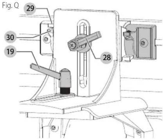
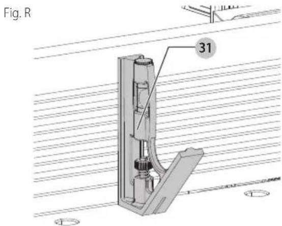
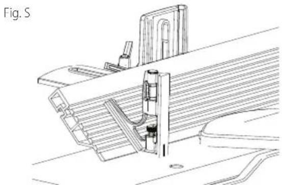
- The fence features adjustable positive stops at the most used fence positions of 90^ and 45^ to the right. To check and adjust the positive stops, proceed as follows:
a. Place a square 31 on the table with one end of the square against the fence as shown. Adjust the fence until it is exactly 90^ to the table.
b. Using supplied hex wrench, turn set screw 29 until it contacts stop 30.
c. Using a square 31, tilt the table to the 45^ position and make sure the fence is 45^ to the table. Adjust the fence if necessary.
d. Using supplied hex wrench, turn set screw 32 until it contacts stop 33.
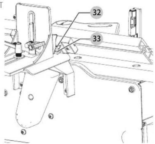
Fig. T
e. These positive stops enable you to rapidly position the table to the 90^ and 45^ settings.
CAUTION: Make sure the fence is in level contact with a surface of the outfeed table.
Adjusting Knives (Fig. U-Y)
WIPING:The knives are sharp.
W P NING: Disconnect machine from power source.
WARNING: Be extremely careful that your hands do not use me in contact with the knives.
WARNING: Make certain that all knives are securely fastened in cutterhead before turning on power.
When it becomes necessary to replace or adjust the knives due to replacement or wear:
- Remove cutterhead guard.
- To replace a knife, disengage the cutterhead lock 4. Rotate cutterhead, loosen four screws 34 and remove bar and knife. Insert new knife and replace bar and securely tighten four screws.
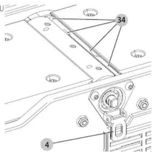
Fig. U
-
To adjust the knives, make sure the cutterhead lock 4 is not engaged. Make sure screws are not overly tightened. Loosen each one half turn or only enough so knife can slide between locking plate and cutterhead.
-
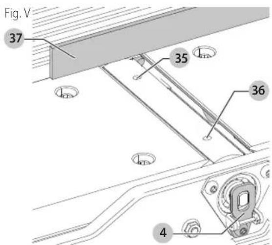
Rotate cutterhead and engage cutterhead lock 4 on cutterhead shaft as shown. This will position knives for proper adjustment to the outfeed table.
- Place a straight edge 37 on the outfeed table extending out over the knife as shown. Using hex wrench supplied, turn screw 35 until knife just touches straight edge. Adjust knife at near end of cutterhead in the same manner turning screw 36. Tighten four screws 34 after adjustment is made. NOTE: Make sure cutterhead lock 4 is disengaged after adjustment is completed and replace cutterhead guard.
- If the knives are set too low, the result will be as shown in Fig. W, and the finished surface will be curved.
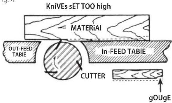
- If the knives are set too high, the work will be gouged at the end of the cut, as shown in Fig. X.
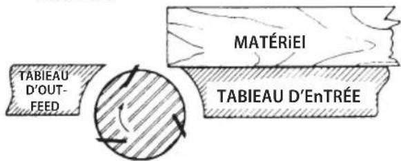
- As a final check, run a piece of work slowly over the knives for 6'' to 8'' (152 mm to 203 mm). The wood should rest firmly on both tables as shown in Fig. Y, with no open spaces under the finished cut.
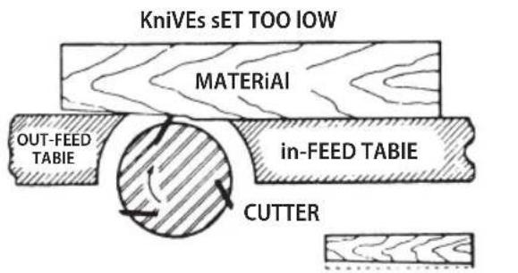
Fig. W
Fig. X
English
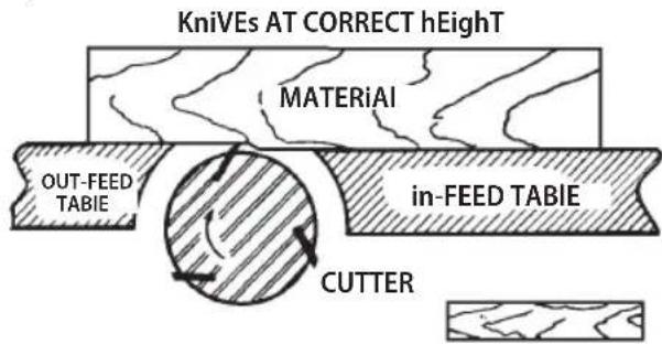
Fig. Y
Cutterhead Guard (Fig. Z)
WARNING: Keep hands away from the head during use.
WARNING: Do not remove the cutterhead guard, do not lock the cutterhead guard, make sure cutterhead
guard spring back freely and touch the fence.
The cutterhead guard 2 is designed to rest against the fence 1. It will automatically move as the workpiece is advanced toward the cutterhead and spring back against the fence after the workpiece passes the cutterhead. With the jointer off check for proper position and motion prior to each operation. Always use the cutterhead guard.
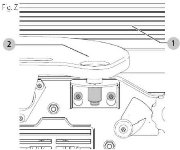
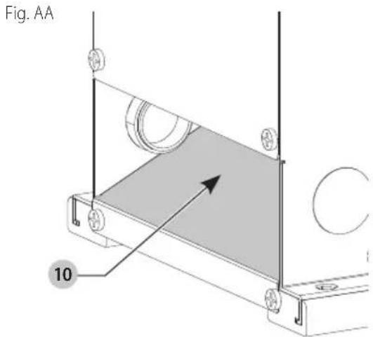
Chip and Dust Chute (Fig. AA)
WARNING: Keep hands out of chip and dust chute times.
A chip and dust chute 10 is provided on the outfeed end of the jointer base for efficient chip removal.
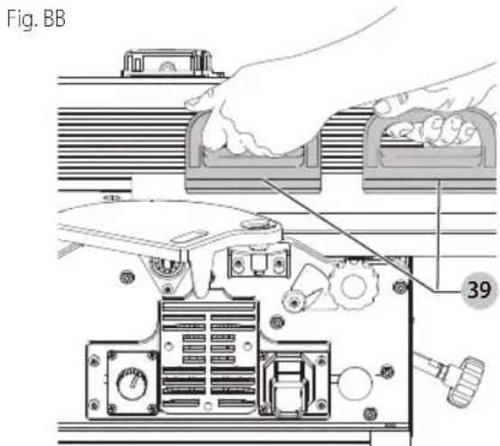
Push Blocks (Fig. BB)
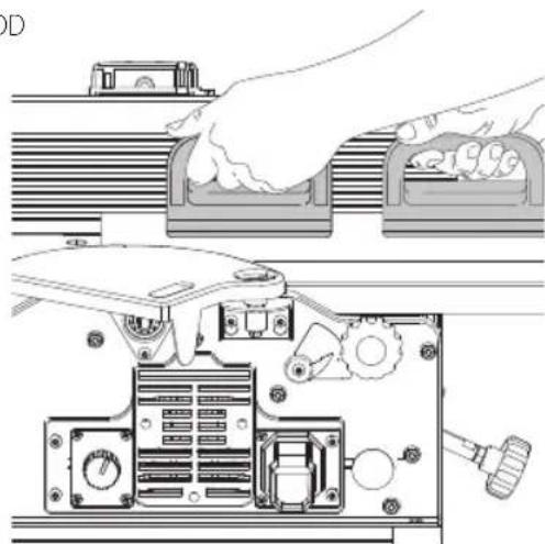
A set of push blocks 39 is supplied with your jointer and should be used whenever possible to minimize all danger to your hands. Fig. BB illustrates using the push blocks properly.
MACHINE USE
WARNING: To reduce the risk of serious personal injury, turn unit off and disconnect it from power source before making any adjustments or removing/installing attachments or accessories.
An accidental start-up can cause injury.
WARNING: Always use cutterhead guard and keep away from cutterhead. Use push blocks whenever possible.
The following directions will give the beginner a start on jointer operations. Use scrap pieces of lumber to check the settings and to get the feel of the operations before attempting regular work.
nOTE: The knives on the jointer will not wear evenly by feeding the wood through the same spot on the table every time. Feed the wood through the jointer at different spots on the table to help eliminate uneven wear of the knives.
English
Definition of Jointing, Planing
Jointing Operations (Fig. CC)
Jointing cuts or edge jointing are made to square an edge of a workpiece. The workpiece is positioned on the jointer with the narrow edge of the workpiece on the infeed table and the major flat surface of the workpiece against the fence. The workpiece is moved from the infeed table, across the cutterhead to the outfeed table.
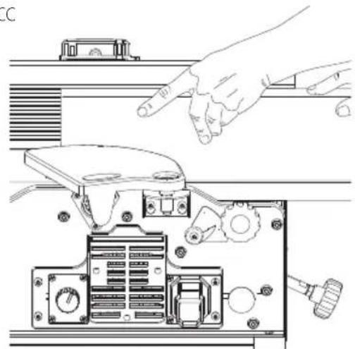
Fig. CC
Planing Operations (Fig. DD)
Planing or surfacing are identical to the jointing operation except for the position of the workpiece. For planing, the major flat surface of the workpiece is placed on the infeed table of the jointer with the narrow edge of the workpiece against the fence. The workpiece is moved from the infeed table, across the cutterhead to the outfeed table. Use push blocks when performing planing operations whenever possible.
Fig. DD
(Fig. BB)
Placement of Hands During Feeding
WARNING: Never pass hands directly over the scatterhead.
At the start of the cut, the left hand holds the work firmly against the infeed table and fence, while the right hand pushes the work toward the knives. After the cut is under way, the new surface rests firmly on the outfeed table as shown in Fig. BB. The left hand should then be moved to the work on the outfeed table, at the same time maintaining flat contact with the fence. The right hand presses the work forward, and before the right hand reaches the cutterhead it should be moved to the work on the outfeed table.
Jointing an Edge (Fig. CC, EE)
WARNING: Do not perform jointing operations on a radial shorter than 10^ (254 mm), narrower than 3 / 4^ (19 mm), or less than 1 / 2^ (12.7 mm) thick.
This is the most common operation for the jointer. Set the guide fence square with the table. Depth of cut should be the minimum required to obtain a straight edge. Hold the best face of the piece firmly against the fence throughout the feed as shown in Fig. CC.
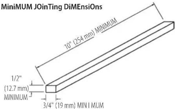
Fig. EE
Planing Warped Pieces
If the wood to be planed is dished or warped, take light cuts until the surface is flat. Avoid forcing such material down against the table; excessive pressure will spring it while passing the knives, and it will spring back and remain curved after the cut is completed.
Planing Short or Thin Work (Fig. BB, FF)
WARNING: Do not perform jointing operations on the medial shorter than 10^ (254 mm), narrower than 3 / 4^ (19 mm), or less than 1 / 2^ (12.7 mm).
When planing short or thin pieces, always use push blocks to minimize all danger to the hands. Fig. BB, illustrates using the push blocks 39 properly.
English
Fiq. FF
Direction of Grain (GG, HH)
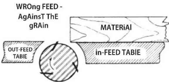
Avoid feeding work into the jointer against the grain. The result will be chipped and splintered edges. Feed with the grain to obtain a smooth surface.
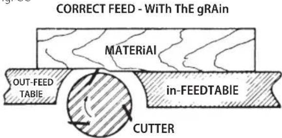
Fig. GG
Fiq. HH
MAINTENANCE
WARNING: To reduce the risk of serious personal injury, turn unit off and disconnect it from power source before making any adjustments or removing/installing attachments or accessories. An accidental start-up can cause injury.
Belt Replacement (Fig. II, JJ)
When it becomes necessary to replace the belt on your jointer:
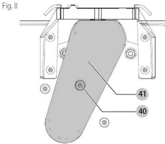
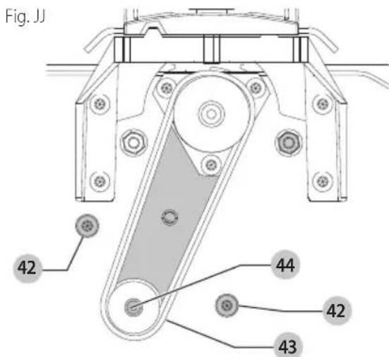
- Remove screw 40 using hex wrench supplied, and remove belt guard 41.
- Loosen three screws 42 to release belt tension and remove belt 43 from pulleys.
- Assemble new belt to the cutterhead and motor pulleys. Press down on motor pulley 44 to tension belt and tighten three screws.
NOTE: There should be approximately 1/4'' (6.4 mm)
deflection in the belt 43 at the center span of the pulleys using light finger pressure. The belt does not require excessive tension to function properly.
- Replace belt guard 41.
Failure to Start
Should your machine fail to start, check to make sure the prongs on the cord plug are making good contact in the outlet. Also, check for blown fuses or open circuit breakers in the line.
Troubleshooting
For assistance with your machine, visit our website at www.craftsman.com for a list of service centers or call the help line at 1-888-331-4569.
Accessories
WARNING: Since accessories, other than those used by CRAFTSMAN, have not been tested with this product, use of such accessories with this tool could be hazardous. To reduce the risk of injury, only CRAFTSMAN recommended accessories should be used with this product.
Recommended accessories for use with your tool are available at extra cost from your local dealer or authorized service center. If you need assistance in locating any accessory, please contact CRAFTSMAN, call 1-888-331-4569.
Cleaning
WARNING: Blow dirt and dust out of all air vents with dry air at least once a week. To minimize the risk of eye injury, always wear ANSI Z87.1 approved eye protection when performing this procedure.
WARNING: Never use solvents or other harsh chemicals for cleaning the non-metallic parts of the tool. These chemicals may weaken the plastic materials used in these parts. Use a cloth dampened only with water and mild soap. Never let any liquid get inside the tool; never immerse any part of the tool into a liquid.
Lubrication and Rust Protection
Apply household floor paste wax to the machine table, extension table or other work surface weekly. You can also use a commercially available protective product designed for this purpose. Follow the manufacturer's instructions for use and safety.
To clean cast iron tables of rust, you will need the following materials: a medium sized scouring pad, a can of spray lubricant and a can of degreaser. Apply the spray lubricant and polish the table surface with the scouring pad.
Degrease the table, then apply the protective product as described above.
Repairs
WARNING: To assure product SAFETY and BILITIES, repairs, maintenance and adjustment (including power cord repairs, and brush inspection and replacement, when applicable) should be performed by a CRAFTSMAN factory service center or a CRAFTSMAN authorized service center. Always use identical replacement parts.
Register Online
Thank you for your purchase. Register your product now for:
- WARRANTY SERVICE: Registering your product will help you obtain more efficient warranty service in case there is a problem with your product.
CONFIRMATION OF OWNERSHIP: In case of an insurance loss, such as fire, flood or theft, your registration of ownership will serve as your proof of purchase.
FOR YOUR SAFETY: Registering your product will allow us to contact you in the unlikely event a safety notification is required under the Federal Consumer Safety Act.
Register online at www.craftsman.com/registration
Three Year Limited Warranty
CRAFTSMAN will repair or replace, without charge, any defects due to faulty materials or workmanship for three years from the date of purchase. This warranty does not cover part failure due to normal wear or tool abuse. For further detail of warranty coverage and warranty repair information, visit www.craftsman.com or call
1-888-331-4569. This warranty does not apply to
accessories or damage caused where repairs have been made or attempted by others. THIS LIMITED WARRANTY IS GIVEN IN LIEU OF ALL OTHERS, INCLUDING THE IMPLIED WARRANTY OF MERCHANTABILITY AND FITNESS FOR A PARTICULAR PURPOSE, AND EXCLUDING ALL INCIDENTAL OR CONSEQUENTIAL DAMAGES. Some states do not allow limitations on how long an implied warranty lasts or the exclusion or limitation of incidental or consequential damages, so these limitations may not apply to you. This warranty gives you specific legal rights and you may have other rights which vary in certain states or provinces.
90 DAY MONEY BACK GUARANTEE
If you are not completely satisfied with the performance of your CRAFTSMAN Power Tool or Nailer for any reason, you can return it within 90 days from the date of purchase with a receipt for a full refund - no questions asked.
LATIN AMERICA: This warranty does not apply to products sold in Latin America. For products sold in Latin America, see country specific warranty information contained in the packaging, call the local company or see website for warranty information.
FREE WARNING LABEL REPLACEMENT: If your warning labels become illegible or are missing, call 1-888-331-4569 for a free replacement.
AVAnCE CORRECTE - AVEC IE Fil
MAINTENANCE
REEMPLACEMENT Gratisuit DES ETIQUETTES
- Definitions: Safety Alert Symbols and Words
- COMPONENTS
- 6" (152 mm) Variable Speed Bench Jointer CMEW020
- General Safety Instructions
- Additional Safety Rules for Jointers
- Additional Safety Information
- Power Connections
- Motor Specifications
- Grounding Instructions (Fig B, C)
- All grounded, cord-connected machines:
- Grounded, cord-connected machines intended for use on a supply circuit having a nominal rating less than 150 Volts:
- SAVE THESE INSTRUCTIONS FOR FUTURE USE
- COMPONENTS (FIG. A)
- Motor
- Intended Use
- ASSEMBLY AND ADJUSTMENTS
- Unpacking and Cleaning
- Assembly Tools Required
- Assembly Time Estimate
- Fence (Fig. D-J)
- Cutterhead Lock (Fig. K)
- Fastening Jointer to Supporting Surface (Fig. M)
- Dust Collector Hose Adapter (Fig. L, M)
- OPERATION
- Stopping and Starting the Jointer (Fig. N)
- Variable Speed Control (Fig. 0)
- Speed Selection Chart
- English
- Depth of Cut Adjustment (Fig. P)
- Fence Adjustments (Fig. Q-T)
- Adjusting Knives (Fig. U-Y)
- Cutterhead Guard (Fig. Z)
- Chip and Dust Chute (Fig. AA)
- Push Blocks (Fig. BB)
- MACHINE USE
- Definition of Jointing, Planing
- Jointing Operations (Fig. CC)
- Planing Operations (Fig. DD)
- Placement of Hands During Feeding
- Jointing an Edge (Fig. CC, EE)
- Planing Warped Pieces
- Planing Short or Thin Work (Fig. BB, FF)
- Direction of Grain (GG, HH)
- MAINTENANCE
- Belt Replacement (Fig. II, JJ)
- Failure to Start
- Troubleshooting
- Accessories
- Cleaning
- Lubrication and Rust Protection
- Repairs
- Register Online
- Three Year Limited Warranty
- DAY MONEY BACK GUARANTEE
- REEMPLACEMENT Gratisuit DES ETIQUETTES
Brand : Craftsman
Model : CMEW020
Category : Milling machine