
AF600 - Measuring equipment Amprobe - Free user manual and instructions
Find the device manual for free AF600 Amprobe in PDF.
| Product Type | Cable Ground Fault Detector (A-Frame) |
| Brand | Amprobe |
| Model | AF600 |
| Dimensions (H x W x D) | 355 x 230 x 120 mm (14 x 9 x 4.7 in) |
| Weight (with batteries) | 1.9 kg (4.2 lb) |
| Power Supply | 6 AA alkaline batteries 1.5 V |
| Battery Life | Approximately 60 hours at 21 °C (70 °F) |
| Auto Power Off | 15 hours of inactivity |
| Display | 1.28 in (33 mm) LCD B&W display with auto backlight |
| Tracing Frequency | 8 kHz (8,192 Hz) |
| Locating Mode | Ground Fault |
| Sensitivity (Cable Locating Mode) | 10 µA at 1 m depth |
| Sensitivity (Fault Mode) | Up to 2 MΩ |
| Operating Temperature | -20 °C to 50 °C (-4 °F to 122 °F), ≤ 90% RH |
| Protection Rating | IP54 (water and dust resistant) |
| Drop Resistance | 1 m (3.28 ft) |
| Electromagnetic Compatibility | IEC 61326-1, Class A (KCC) |
| Safety Compliance | IEC 61010-1, CSA/UL 61010-1, CE, CENELEC |
| Compatible Transmitter | UAT-600-T |
| Maintenance | Battery replacement (6 AA); clean with dry cloth |
| Spare Parts | Stakes, rubber guards, test leads |
Frequently Asked Questions - AF600 Amprobe
User questions about AF600 Amprobe
0 question about this device. Answer the ones you know or ask your own.
Ask a new question about this device
Download the instructions for your Measuring equipment in PDF format for free! Find your manual AF600 - Amprobe and take your electronic device back in hand. On this page are published all the documents necessary for the use of your device. AF600 by Amprobe.
USER MANUAL AF600 Amprobe
natural_image
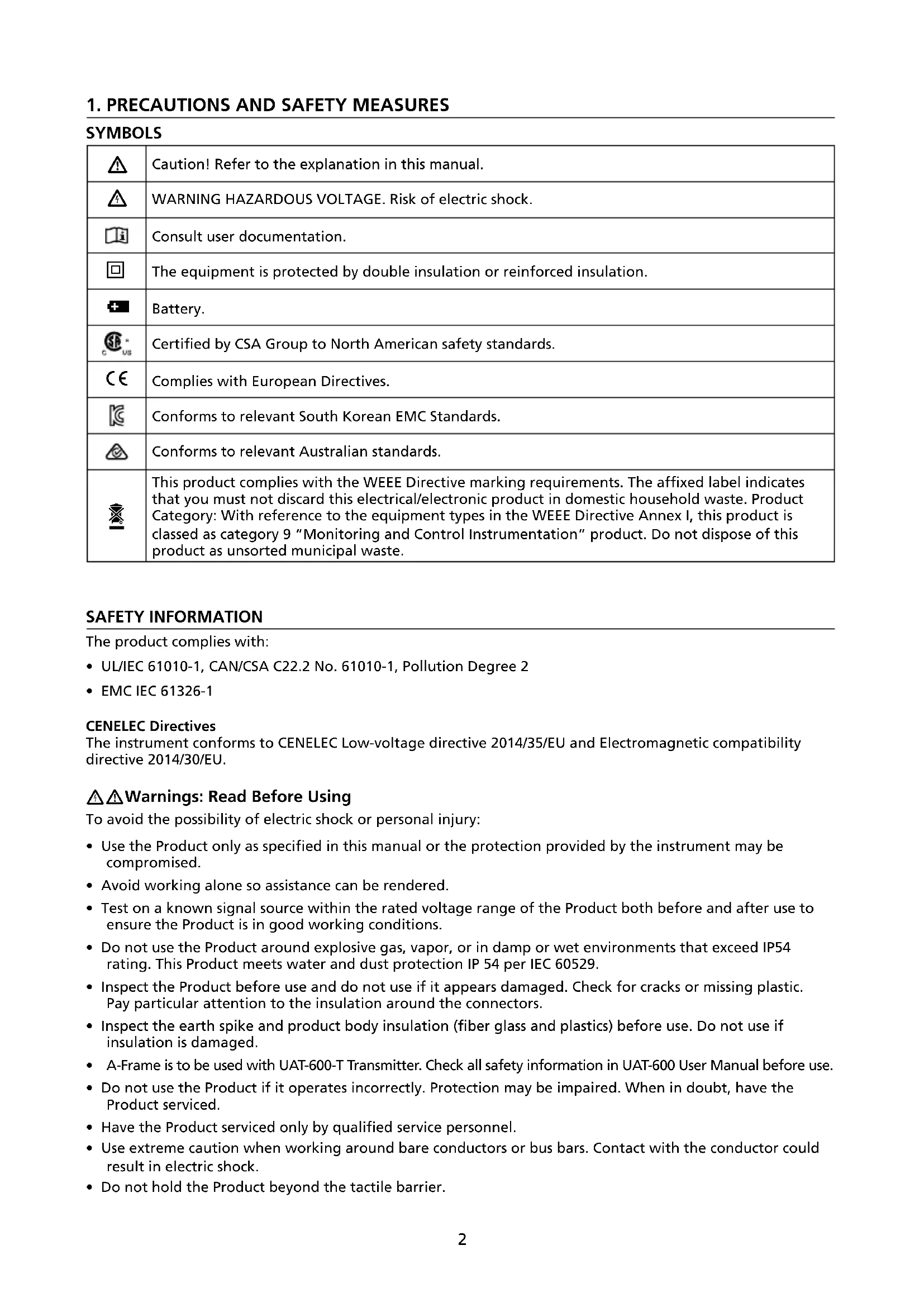
Line drawing of a mechanical device with articulated arms and two protruding legs (no text or symbols)AF-600
A-Frame cable ground fault finder
User Manual
ENGFRE SPA
AF-600
A-Frame cable ground fault finder
User Manual
Limited Warranty and Limitation of Liability
Your Amprobe product will be free from defects in material and workmanship for one year from the date of purchase unless local laws require otherwise. This warranty does not cover fuses, disposable batteries or damage from accident, neglect, misuse, alteration, contamination, or abnormal conditions of operation or handling. Resellers are not authorized to extend any other warranty on the behalf of Amprobe. To obtain service during the warranty period, return the product with proof of purchase to an authorized Amprobe Service Center or to an Amprobe dealer or distributor. See Repair Section for details. THIS WARRANTY IS YOUR ONLY REMEDY. ALL OTHER WARRANTIES - WHETHER EXPRESS, IMPLIED OR STATUTORY - INCLUDING IMPLIED WARRANTIES OF FITNESS FOR A PARTICULAR PURPOSE OR MERCHANTABILITY, ARE HEREBY DISCLAIMED. MANUFACTURER SHALL NOT BE LIABLE FOR ANY SPECIAL, INDIRECT, INCIDENTAL OR CONSEQUENTIAL DAMAGES OR LOSSES, ARISING FROM ANY CAUSE OR THEORY. Since some states or countries do not allow the exclusion or limitation of an implied warranty or of incidental or consequential damages, this limitation of liability may not apply to you.
Repair
All Amprobe returned for warranty or non-warranty repair or for calibration should be accompanied by the following: your name, company's name, address, telephone number, and proof of purchase. Additionally, please include a brief description of the problem or the service requested and include the test leads with the meter. Non-warranty repair or replacement charges should be remitted in the form of a check, a money order, credit card with expiration date, or a purchase order made payable to Amprobe.
In-warranty Repairs and Replacement – All Countries
Please read the warranty statement and check your battery before requesting repair. During the warranty period, any defective test tool can be returned to your Amprobe distributor for an exchange for the same or like product. Please check the "Where to Buy" section on amprobe.com for a list of distributors near you. Additionally, in the United States and Canada, in-warranty repair and replacement units can also be sent to an Amprobe Service Center (see address below).
Non-warranty Repairs and Replacement – United States and Canada
Non-warranty repairs in the United States and Canada should be sent to an Amprobe Service Center. Call Amprobe or inquire at your point of purchase for current repair and replacement rates.
USA: Canada:
Amprobe Amprobe
Everett, WA 98203 Mississauga, ON L4Z 1X9
Tel: 877-AMPROBE (267-7623) Tel: 905-890-7600
Non-warranty Repairs and Replacement – Europe
European non-warranty units can be replaced by your Beha-Amprobe distributor for a nominal charge. Please check the "Where to Buy" section on beha-amprobe.com for a list of distributors near you.
Beha-Amprobe
Division and reg. trademark of Fluke Corp. (USA)
Germany* United Kingdom The Netherlands - Headquarters**
In den Engematten 14 52 Hurricane Way Science Park Eindhoven 5110
79286 Glottertal Norwich, Norfolk 5692 EC Son
Germany NR6 6JB United Kingdom The Netherlands
Phone: +49 (0) 7684 8009 - 0 Phone: +44 (0) 1603 25 6662 Phone: +31 (0) 40 267 51 00
beha-amprobe.de
beha-amprobe.com
beha-amprobe.com
*(Correspondence only – no repair or replacement available from this address. European customers please contact your distributor.)
**single contact address in EEA Fluke Europe BV
CONTENTS
- PRECAUTIONS AND SAFETY MEASURES ......2
- INTRODUCTION ....3
- OPERATION .... 3
- FAULT LOCATE SCREEN ....4
- UAT-600-T TRANSMITTER....4
5.1 Transmitter Display....4
5.2 Transmitter Controls and Connections....4 - USING THE A-FRAME TO PINPOINT A FAULT....5
6.1 Preparing a Cable 5
6.2 Connecting the UAT-600-T Transmitter 6
6.3 Pinpointing the Fault with the A-Frame....7 - BATTERY REPLACEMENT....9
- SPECIFICATIONS....10
1. PRECAUTIONS AND SAFETY MEASURES
SYMBOLS
 | Caution! Refer to the explanation in this manual. |
 | WARNING HAZARDOUS VOLTAGE. Risk of electric shock. |
 | Consult user documentation. |
| ### | The equipment is protected by double insulation or reinforced insulation. |
| ### | Battery. |
| ### | Certified by CSA Group to North American safety standards. |
| ### | Complies with European Directives. |
| ### | Conforms to relevant South Korean EMC Standards. |
| ### | Conforms to relevant Australian standards. |
| ### | This product complies with the WEEE Directive marking requirements. The affixed label indicates that you must not discard this electrical/electronic product in domestic household waste. Product Category: With reference to the equipment types in the WEEE Directive Annex I, this product is classed as category 9 “Monitoring and Control Instrumentation” product. Do not dispose of this product as unsorted municipal waste. |
SAFETY INFORMATION
The product complies with:
- UL/IEC 61010-1, CAN/CSA C22.2 No. 61010-1, Pollution Degree 2
• EMC IEC 61326-1
CENELEC Directives
The instrument conforms to CENELEC Low-voltage directive 2014/35/EU and Electromagnetic compatibility directive 2014/30/EU.
⚠️⚠️Warnings: Read Before Using
To avoid the possibility of electric shock or personal injury:
- Use the Product only as specified in this manual or the protection provided by the instrument may be compromised.
- Avoid working alone so assistance can be rendered.
- Test on a known signal source within the rated voltage range of the Product both before and after use to ensure the Product is in good working conditions.
- Do not use the Product around explosive gas, vapor, or in damp or wet environments that exceed IP54 rating. This Product meets water and dust protection IP 54 per IEC 60529.
- Inspect the Product before use and do not use if it appears damaged. Check for cracks or missing plastic. Pay particular attention to the insulation around the connectors.
- Inspect the earth spike and product body insulation (fiber glass and plastics) before use. Do not use if insulation is damaged.
- A-Frame is to be used with UAT-600-T Transmitter. Check all safety information in UAT-600 User Manual before use.
- Do not use the Product if it operates incorrectly. Protection may be impaired. When in doubt, have the Product serviced.
- Have the Product serviced only by qualified service personnel.
- Use extreme caution when working around bare conductors or bus bars. Contact with the conductor could result in electric shock.
-
Do not hold the Product beyond the tactile barrier.
-
Remove the Product from measuring position before opening the Product case or battery cover.
- Never operate the Product with the battery cover removed or the case open.
- Use caution when working with voltages above 30 V AC RMS, 42 V AC peak, or 60 V DC. These voltages pose a shock hazard.
- Do not attempt to connect to any circuit carrying voltage.
- To avoid false readings that can lead to electrical shock and/or injury, replace the batteries as soon as the low battery indicator appears. Check Product operation on a known source before and after use.
- Use only 6 x AA batteries properly installed in the battery compartment, to power the Product (see Section 7: BATTERY REPLACEMENT).
- When servicing, use only specified user serviceable replacement parts.
- Adhere to local and national safety codes. Individual protective equipment must be used to prevent shock and arc blast injury where hazardous live conductors are exposed.
• For use by competent persons only. - Remove the batteries if the Product is not used for an extended period of time, or if stored in temperatures above 140 °F (60 °C). If the batteries are not removed, battery leakage can damage the Product.
- Follow all battery care from the battery manufacturer.
2. INTRODUCTION
The AF-600 A-Frame cable ground fault finder is an optional accessory specifically designed for the Amprobe UAT-600 series. In combination with the Transmitter, it will pinpoint the place where a cable metal conductor (either a sheath or a metallic conductor of the wire) touches the ground. It can also detect other conductors to ground faults such as pipeline coating defects.
natural_image
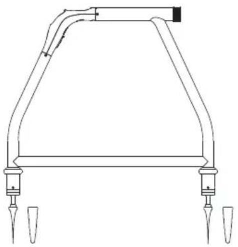
Technical line drawing of a mechanical component with two ports and a curved top structure (no text or symbols)3. OPERATION
1 On/off: Press for 2 seconds to turn on or turn off the A-Frame.
② Speaker Volume 📋 Press repeatedly to loop between mute and three levels of volume.
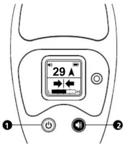
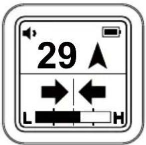
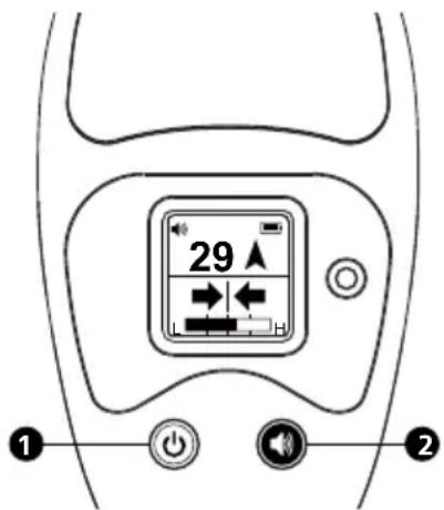
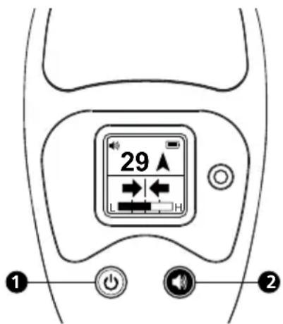
4. FAULT LOCATE SCREEN
A short press on the On/Off button will switch on the unit, defaulting to the Fault Locate screen.
1 Speaker Volume Setting
2-digit Fault Signal Level
3 Left/Right Cable Position Indicator
4 Signal Strength Indicator
5 Battery Indicator
6 Fault Direction Compass
7 Light Sensor
5. UAT-600-T TRANSMITTER
The UAT-600-T Transmitter is used to apply a fault find signal to the utility under test. Use the Transmitter in combination with the A-Frame to receive the signal and pinpoint a place of the fault.
5.1 Transmitter Display
The contents of the screen depend on the function being performed. The below diagram shows general functions of the Transmitter screen (for further details, see the UAT-600 User Manual).
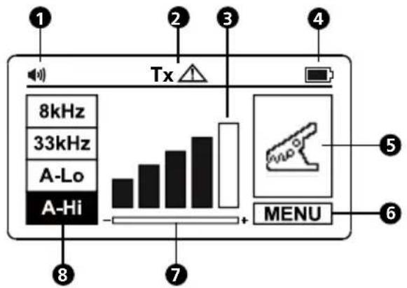
①Speaker Volume
② Output Hazardous Voltage
3 Signal Output Level
4 Battery Indicator
5 Locating Mode
6 Menu
7 Gain Setting Reminder
8 Frequency Selection
5.2 Transmitter Controls and Connections
The below diagram shows general functions of the Transmitter controls and connections (for further details, see the UAT-600 User Manual).
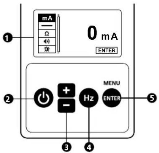
① LCD Display
2 Power ON/OFF
3 Down/Decrease + / -
4 Frequency Selection Hz
5 Enter/Menu
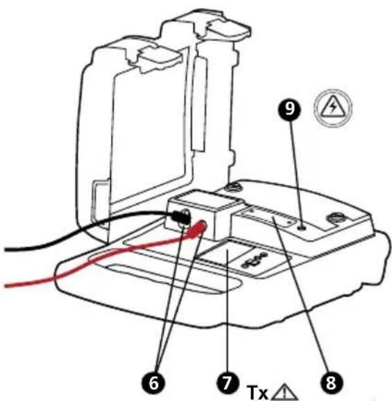
⑥ Terminals for direct connection and signal clamp
⑦ Tx △ Hazardous output voltage indicator. The icon on the screen indicates the transmitter is outputting voltages ≥30 V.
8 Protection fuse
9 Hazardous voltage indicator (over 30 V)
The red solid light indicates the presence of AC voltage ≥ 30 V on the circuit under direct connection mode.
The red blinking light indicates the presence of voltages above 30 V on the Transmitter terminals under A-Lo and A-Hi mode (generated and/or measured). In case of the presence of line voltage >50 V (typical) during the operation of A-Lo or A-Hi mode, the transmitter automatically disables A-Lo and A-Hi modes, the red solid light indicator appears.
△ Always check the presence of voltage on the circuit by additional voltage tester.
⚠️ Use caution when above voltage indication warnings are ON.
6. USING THE A-FRAME TO PINPOINT A FAULT
WARNING
Always be aware of the location of buried utilities (especially buried power lines) when pushing the spikes of the A-Frame into the soil.
The spikes of the A-Frame are sharp. Always handle carefully to avoid injury.
The A-Frame is used to detect ground faults on cables and pipes. In the case of cables, faults are usually caused by insulation damage allowing the metallic sheath or internal conductor to become in contact with the ground. In the case of pipes, the faults consist of coating defects.
The A-Frame works in conjunction with the UAT-600-T Transmitter. The Transmitter is used to apply a fault find signal to the utility under test, and the A-Frame is used to receive the signal and pinpoint a place of the fault.
6.1 Preparing a Cable
- Disconnect and isolate the cable on both ends. Make sure to disconnect all ground bonding. This will ensure that the test signal traveling through the ground fault is not masked or doesn't interfere with the one conducted by grounding bonding to the ground. The A-Frame cannot distinguish between these two signals.
- Use the resistance measuring function on the Transmitter, or a dedicated resistance measuring device, to identify a cable with a fault to ground. The A-Frame will typically detect faults up to 2 MΩ (depending on the distance from the Transmitter, soil conditions, etc.).
When at A-Lo / A-Hi mode, the indicator will blink. In case of a voltage presence ≥ 10 V (typical) on the circuit under test, the measurement will be opt out under MENU screen.
- Optionally, you can precisely detect and mark cable locations using the UAT-600-R receiver. Refer to the UAT-600 User Manual for detailed instructions how to locate underground utilities.
6.2 Connecting the UAT-600-T Transmitter
⚠️⚠️Warnings: Read Before Using
- Use the UAT-600-T Transmitter only as specified in UAT-600 User Manual or the protection provided by the instrument may be compromised.
- Check and read all safety information in UAT-600 User Manual before use.
- Inspect the test leads before use. Do not use if insulation is damaged or metal is exposed.
- Check the test leads for continuity. Replace damaged test leads before using the Product.
- Never operate the Product with the battery cover removed or the case open.
- Use extreme caution when working around bare conductors or bus bars. Contact with the conductor could result in electric shock.
- Disconnect and isolate the cable on both ends before connecting the UAT-600-T to the cable.
Setting up the Transmitter
- Turn the Transmitter on by pressing power button for 2 seconds.
- Connect the black and red test leads to the Transmitter inputs. The Transmitter will switch automatically to Direct Connection Mode and the display will show the direct connection icon.
- Insert the ground stake into the ground a few yards away, perpendicular to the line. Connect the black lead to the ground stake with an alligator clip.
- Connect a red test lead to the target line.
- Pres Hz button repeatedly to select "A-LO" (A-Frame low signal) or "A-Hi" (A-Frame high signal). Use "A-LO" for higher accuracy pinpointing. Use the "A-Hi" setting if the line to be surveyed is long or the fault resistance is high.
- Press the "+/-" buttons to set the output to level one. Increase the level if the resulting signal strength is poor. Increasing the signal unnecessarily may result in the signal "bleeding off" onto other services and creating misleading "ghost" signals. It will also drain more power from the battery.
Note: When connected, the Transmitter will emit a beep tone. The better the connection to the line and ground, the faster the beep tone will be. Check for a good connection by disconnecting and then reconnecting the red lead. It is also possible to check the signal current being supplied by the Transmitter by entering the user menu and selecting the mA option.
Things that can affect the quality of connection are a rusty pipe connection point (clean the connection area with a wire brush) or poor grounding. To improve the connection quality due to poor grounding, try inserting the stake into damp ground. If necessary, dampen the surrounding ground with water. If grounding is still an issue, try connecting test lead to a manhole cover surround. Avoid connecting to fence railings as these may create return signal currents along the fencing that will interfere with the locating signal.
Note: If the signal level bars do not fill, this indicates that the impedance of the line is limiting the current output. Increasing the output beyond this point will not increase the signal. If more signal is required, check the quality of the connection to the line and ground.
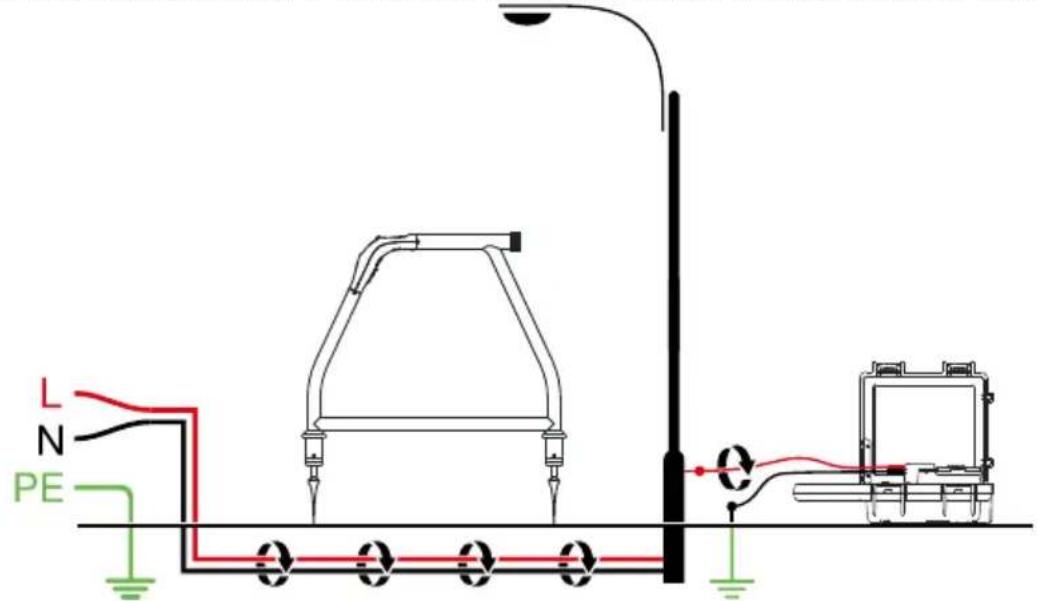
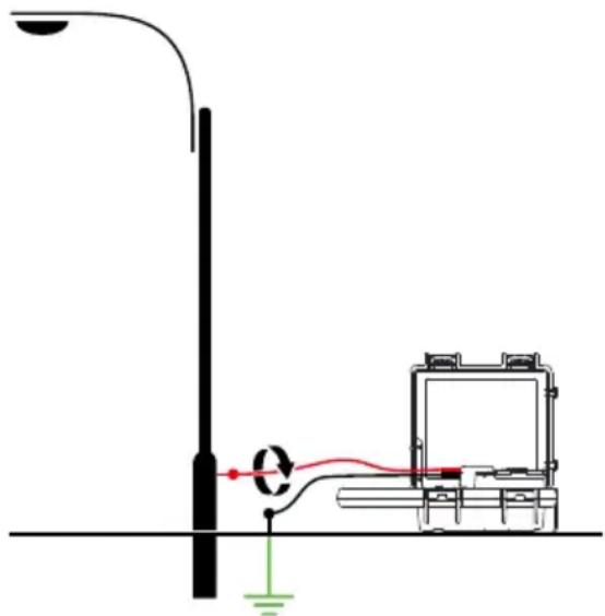
When connecting to large diameter pipes and cables, it is sometimes not possible to find a suitable projection to apply the alligator clip. If the material is ferrous, use a magnet to make contact to the line and then attach
the alligator clip to a magnet. For example: making a connection to a street lighting circuit. Usually it is practice to connect the sheath of a lighting cable to the metallic inspection cover of a street lamp. Making a connection to the inspection plate will induce a signal to the cable via the plate and sheath. Usually, there is no projection on the plate on which to clip so using a magnet on the plate provides a suitable clipping point.
6.3 Pinpointing the Fault with the A-Frame
-
Remove the rubber spike covers from the A-Frame.
-
Press the On/Off button to turn the unit on.
-
Use the Left/Right indicator arrows to position A-Frame over the cable. At that point, the bar graph at the bottom of the display will show maximum value for the test signal strength. The speaker will emit a pulsed tone on one side of the cable and a solid tone on the other, so it is possible to locate the cable without looking at the screen. If necessary, adjust the volume by using short presses on the speaker button.
Note:
- If the spikes are not in the ground or there is only a very low signal, the 2-digit Fault Signal Level reading and Fault Direction Compass arrow may not be visible. These are only shown when there is a valid fault find signal.
- If the position of the line is different when comparing the Left/Right position to the peak bar graph position, there could be a distorted signal that may affect readings. Proceed with caution.
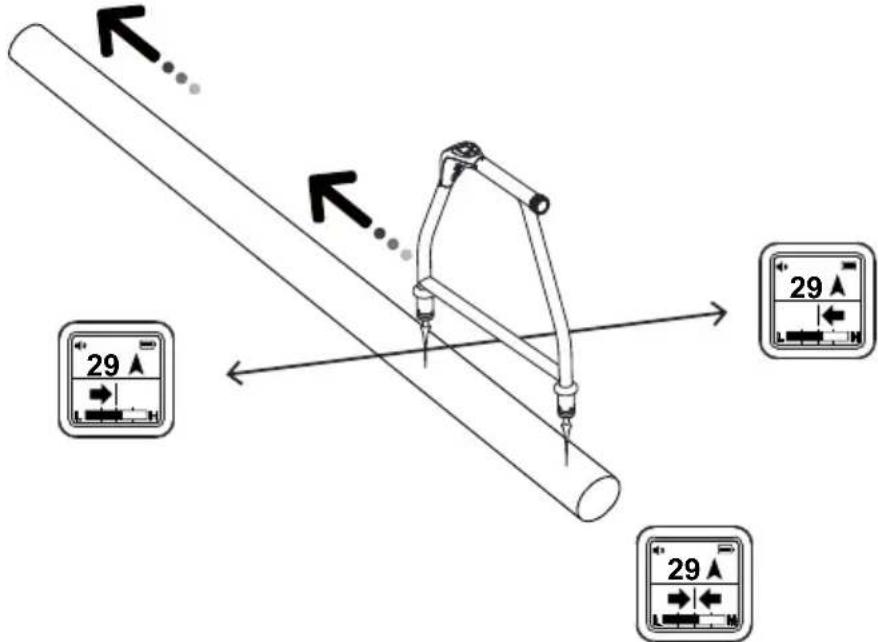
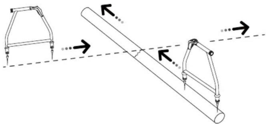
- Start near the Transmitter. Hold the A-Frame in line with the route of the cable. Walk along the route of the line placing the spikes of the A-Frame in the ground every two or three paces. Allow a couple of seconds for the readings to settle before moving to the next position. Keep the A-Frame aligned with the cable by using the Left/Right arrows.
Note: Initially, the Fault Direction Compass arrow on the display may point towards the Transmitter grounding stake, but as you continue walking along the cable away from the Transmitter it will fluctuate or disappear. The 2-digit Fault Signal Level may also continue decreasing or disappear. This is because the A-Frame detects signals conducted by the Transmitter ground stake and a cable fault is further along the line.
-
In proximity of the fault, the A-Frame will detect the fault signal and the Fault Direction Compass arrow will point forward.
-
Continue moving forward. The 2-digit Fault Signal Level reading will increase as the fault is neared. When you cross the place of the fault, the Compass Fault Detection will change a direction and the 2-digit Fault Signal level will start decreasing as you go away from the fault. Maximum reading will be just before and just after the fault.
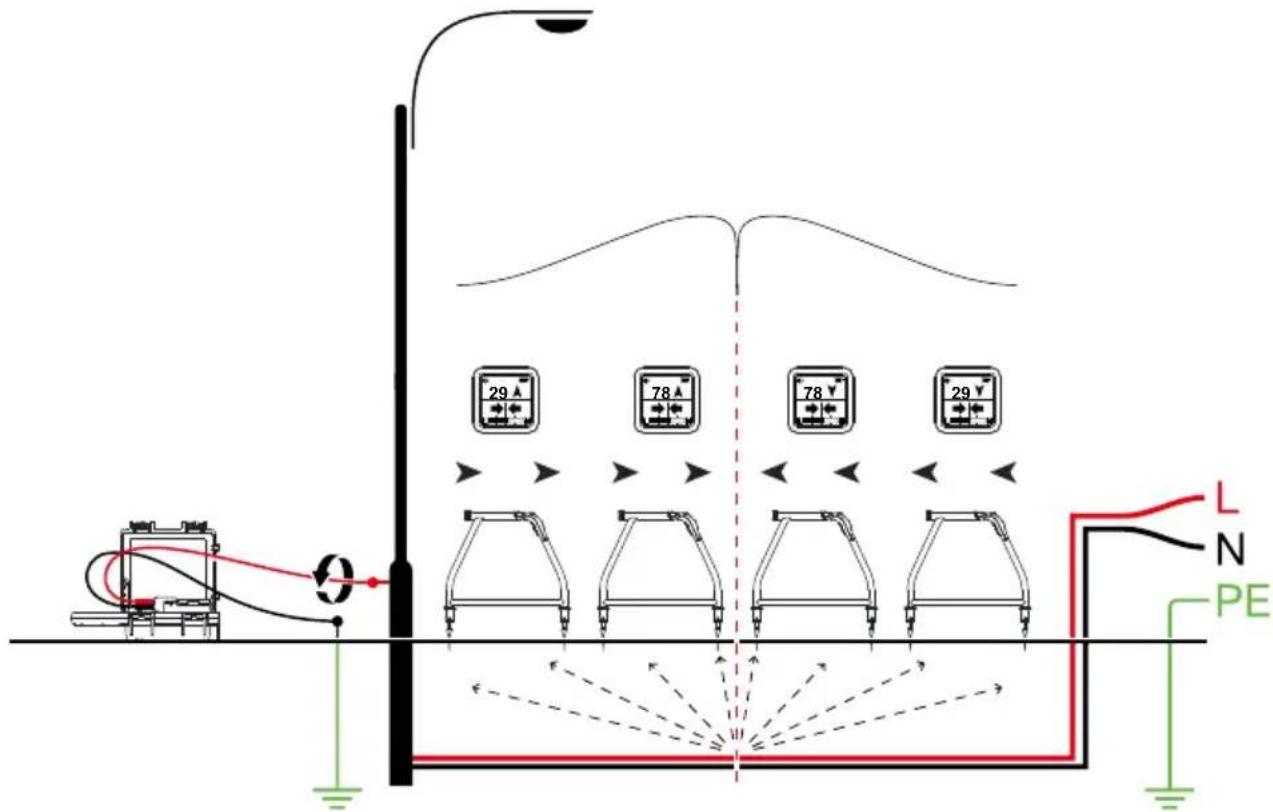
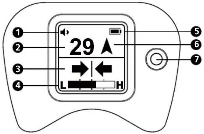
- Carefully place the A-Frame before and after the fault to pinpoint it. Repeating this in a line perpendicular to the direction of the cable will pinpoint the fault laterally.
natural_image
Diagram showing two mechanical lever systems with arrows indicating motion, no text or symbols present
If it is suspected that there is just one fault, insert the A-frame approximately 3 ft (1 m) from the ground stake. Note the two digit number - this is approximately the maximum reading that will be measured over the fault.
7. BATTERY REPLACEMENT
The unit is powered by six AA alkaline batteries (included). When the battery indicator on the screen indicates empty 1, the batteries should be replaced.
Accessing the Batteries
Unscrew the battery cap on the A-Frame handle and remove by gently pulling the battery holder.
When inserting the battery pack, ensure the correct orientation of the holder. The two contacts at the end of the battery pack should be at the bottom as shown in the adjacent graphic.

Replace all batteries at the same time. Do not mix new and old batteries. This can lead to batteries being reverse charged and can cause damage, heat and even fire.
- SPECIFICATIONS
| Tracing mode (de-energized) 8 kHz (8,192 Hz) | |
| Locating mode Ground fault locating | |
| Sensitivity (typical) | Cable locate mode at 1 meter depth: 10 uAFault locate mode: up to 2 MΩ fault |
| Display backlight Automatic | |
| Audio indication Speaker indicates left/right by pulsed/continuous tone | |
| Compatible transmitter UAT-600-T Transmitter | |
| Display 1.28 in (33 mm) 128 x 128 | BW outdoor LCD display with auto backlight |
| Update rate Instantaneous | |
| Operating temperature and humidity | -4 °F to 122 °F (-20 °C to 50 °C), ≤90% RH |
| Storage temperature and humidity | -40 °F to 140 °F (-40 °C to 60 °C), ≤90% RH |
| Operating altitude < 6561 ft (< 2000 m) | |
| Pollution degree 2 | |
| Water and dust resistance IP54 | |
| Drop proof 3.28 ft (1 m) | |
| Power supply Six (6) 1.5 V AA alkaline batteries | |
| Auto power off 15 minutes idle | |
| Battery life Approx. 60 hours at 70 °F (21 °C) (Typical) | |
| Low battery indication | Blinking |
| Agency approval | IEC 61010-1CSA/UL 61010-1 |
| Safety compliance | IEC 61326-1Korea (KCC): Class A Equipment (Industrial Broadcasting & Communication Equipment) [1][1] This product meets requirements for industrial (Class A) electromagnetic wave equipment and the seller or user should take notice of it. This equipment is intended for use in business environments and is not to be used in homes. |
| Electromagnetic Compatibility | |
| Size (H x W x L) | Approx. 14 x 9 x 4.7 in (355 x 230 x 120 mm) |
| Weight Approx. 4.2 lb (1.9 kg) (batteries installed) | |
AF-600
natural_image
Technical line drawing of a mechanical component with two protruding ports and a curved top structure (no text or symbols)3. FONCTIONNEMENT
natural_image
Diagram of a mechanical setup with a vertical pole, connected to a cart and a red wire, showing no text or symbols.natural_image
Diagram showing two mechanical lever systems with arrows indicating motion, no text or symbols present
natural_image
Pure technical line drawing of a mechanical component with no text or symbols3. FUNCIONAMIENTO
Visit amprobe.com for
- Catalog
- Application notes
• Product specifications - User manuals
Amprobe®
amprobe.com
Division of Fluke Corp.
6920 Seaway Blvd.
M/S 143F
Everett, WA 98203 USA
Tel: 877-AMPROBE (267-7623)
Beha-Amprobe®
beha-amprobe.com
c/o Fluke Europe BV
Science Park
Eindhoven 5110
NL-5692 EC Son
Tel.: +49 (0) 7684 8009 - 0


- AF-600
- A-Frame cable ground fault finder
- User Manual
- Limited Warranty and Limitation of Liability
- Repair
- In-warranty Repairs and Replacement – All Countries
- Non-warranty Repairs and Replacement – United States and Canada
- Non-warranty Repairs and Replacement – Europe
- Beha-Amprobe
- CONTENTS
- PRECAUTIONS AND SAFETY MEASURES
- SAFETY INFORMATION
- CENELEC Directives
- ⚠️⚠️Warnings: Read Before Using
- INTRODUCTION
- OPERATION
- FAULT LOCATE SCREEN
- UAT-600-T TRANSMITTER
- Transmitter Display
- Transmitter Controls and Connections
- USING THE A-FRAME TO PINPOINT A FAULT
- WARNING
- Preparing a Cable
- Connecting the UAT-600-T Transmitter
- Setting up the Transmitter
- Pinpointing the Fault with the A-Frame
- Note:
- BATTERY REPLACEMENT
- Accessing the Batteries
- FONCTIONNEMENT
- FUNCIONAMIENTO
- Visit amprobe.com for
- Amprobe®
- Beha-Amprobe®
Brand : Amprobe
Model : AF600
Category : Measuring equipment