
CMXEVBCV1260L - Vacuum Cleaner Craftsman - Free user manual and instructions
Find the device manual for free CMXEVBCV1260L Craftsman in PDF.

| Product Type | Wet/Dry Vacuum |
| Brand | Craftsman |
| Model | CMXEVBCV1260L |
| Supply Voltage | 120 V |
| Plug Type | Grounded (3-pin) |
| Blower Function | Yes, via blower port |
| Automatic Liquid Shut-off | Yes, via float |
| Dry Debris Filter | Cartridge filter + optional disposable filter bag |
| Wet Debris Filter | Foam sleeve |
| Included Accessories | Hose, 2 extension tubes, 35.6 cm floor nozzle, 20.3 cm utility nozzle, tool holder, strap |
| Number of Casters | 4 |
| Tank Drain | Drain plug |
| Warranty | 3 years (limited) |
| Money-back Guarantee | 90 days |
| Customer Service | 1-888-331-4569 |
| Safety Instructions | Use safety glasses, unplug before maintenance, do not vacuum flammable materials |
| Filter Maintenance | Clean the cartridge filter or foam sleeve regularly |
| Tank Capacity | Not specified in the manual |
Frequently Asked Questions - CMXEVBCV1260L Craftsman
User questions about CMXEVBCV1260L Craftsman
0 question about this device. Answer the ones you know or ask your own.
Ask a new question about this device
Download the instructions for your Vacuum Cleaner in PDF format for free! Find your manual CMXEVBCV1260L - Craftsman and take your electronic device back in hand. On this page are published all the documents necessary for the use of your device. CMXEVBCV1260L by Craftsman.
USER MANUAL CMXEVBCV1260L Craftsman
IF YOU HAVE QUESTIONS OR COMMENTS, CONTACT US.
POUR TOUTE QUESTION OU TOUT COMMENTAIRE, NOUS CONTACTER.
SI TIENE DUDAS O COMENTARIOS, CONTÁCTENOS.
1-888-331-4569
WWW.CRAFTSMAN.COM
Definitions: Safety Alert Symbols and Words
This instruction manual uses the following safety alert symbols and words to alert you to hazardous situations and your risk of personal injury or property damage.

NGER:
Indicates an imminently hazardous situation which, if not avoided, will result in death or

ARNING:
Indicates a potentially hazardous situation which, if not avoided, could result in death or

UTION:
Indicates a potentially hazardous situation which, if not avoided, may result in minor or

without word) Indicates a safety related message.
NOTICE: Indicates a practice not related to personal injury which, if not avoided, may result in property damage.
natural_image
Line drawing of a mechanical device with wheels and a labeled component (no text or symbols beyond the number 18)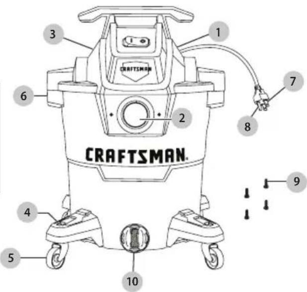
Tools Included:
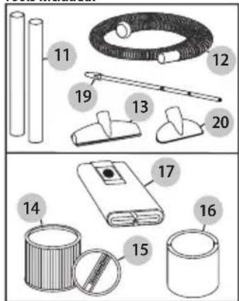
Filters Included:
COMPONENTS
1 Vacuum
2 Hose Inlet
3 Blower Port (not pictured)
4 Caster Feet (4)
5 Casters (4)
6 Lid Latches
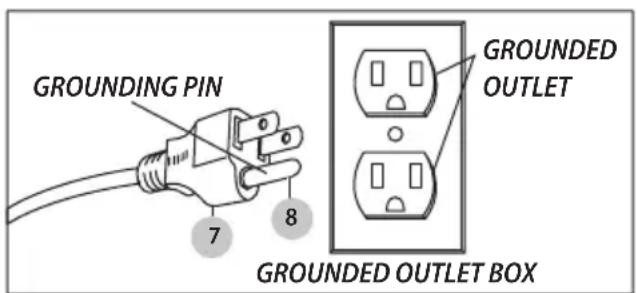
7 Plug
8 Grounding Pin
9 Screws (4)
10 Tank Drain
11 Extension Wands (2)
12 Hose
13 14" Floor Nozzle
14 Cartridge Filter
15 Retainer
16 Foam Sleeve
17 Filter Bag
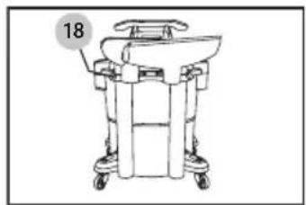
18 Tool Holder
19 Hose Strap
20 8" Utility Nozzle
WARNING:
Read all safety warnings and all instructions. Failure to follow the warnings and
instructions may result in electric shock, fire and/or serious injury.
WARNING:
Never modify the product or any part of it. Damage or personal injury could result.

WARNING:
To reduce the risk of injury, read the instruction manual.
If you have any questions or comments about this or any product, call CRAFTSMAN toll free at: 1-888-331-4569.
CMXEVBCV1260L
IMPORTANT SAFETY INSTRUCTIONS
Read all safety rules carefully before attempting to operate.
ANGER: Never operate this unit when flammable materials or vapors are present.
What can happen How to prevent it
| Because electrical devices produce arcs or sparks, flammable materials and vapors can cause a fire or explosion. | Never use the vacuum around flammable materials or vapors. |
WARNING: ALWAYS DISCONNECT THE PLUG FROM THE WALL OUTLET BEFORE REMOVING THE TANK COVER.
What can happen How to prevent it
| Vacuum could turn on. | Always unplug power cord from the wall outlet before removing the tank cover. |
WARNING: ALWAYS WEAR EYE PROTECTION.
What can happen How to prevent it
| Rocks or debris can be blown or ricochet into the eyes or face which can result in serious injury. | Always wear eye protection while operating vacuum. |
When using an electrical appliance, basic precautions should always be followed, including the following: READ ALL INSTRUCTIONS BEFORE USING THIS APPLIANCE.
WARNING: TO REDUCE THE RISK OF FIRE ELECTRIC SHOCK OR INJURY:
a) Do not leave appliance when plugged in. Unplug from outlet when not in use and before servicing. Connect to a properly grounded outlet only. See Grounding Instructions.
b) Do not expose to rain - store indoors.
c) Do not allow to be used as a toy. Close attention is necessary when used by or near children.
d) Use only as described in this manual. Use only Manufacturer's recommended attachments.
e) Do not use with damaged cord or plug. If appliance is not working as it should, has been dropped, damaged, left outdoors, or dropped into water, return
to service center.
f) Do Not: pull or carry by cord, use cord as a handle, close a door on cord or pull cord around sharp edges or corners. Do not run appliance over cord. Keep cord away from heated surfaces.
g) Do not unplug by pulling on cord. To unplug, grasp the plug; not the cord.
h) Do not handle plug or appliance with wet hands.
i) Do not put any object into openings. Do not use with any openings blocked; keep free of dust, lint, hair and anything that may reduce air flow.
j) Keep hair, loose clothing, fingers and all parts of body away from openings and moving parts.
k) Do not pick up anything that is burning or smoking, such as cigarettes, matches or hot ashes.
1) Do not use without dust bag and/or filters in place.
m) Turn off all controls before unplugging.
n) Use extra care when cleaning on stairs.
o) Do not use to pick up flammable or combustible liquids such as gasoline or use in areas where they may be present.
p) Do not use the cleaner as a sprayer of flammable liquids such as oil base paints, lacquers, household cleaners, etc.
a) Do not vacuum toxic, carcinogenic, combustible or other hazardous materials such as asbestos, arsenic, barium, beryllium, lead, pesticides or other health endangering materials. Specially designed units are available for these purposes.
r) Do not pick up soot, cement, plaster or drywall dust without cartridge filter and collection filter bag in place. These are very fine particles that may pass through the foam and affect the performance of the motor or be exhausted back into the air. Additional collection filter bags are available.
s) Do not leave the cord lying on the floor once you have finished the cleaning job. It can become a tripping hazard.
t) Use special care when emptying heavily loaded tanks.
u) To avoid spontaneous combustion, empty tank after each use.
v) The operation of a utility vac can result in foreign objects being blown into eyes, which can result in eye damage. Always wear safety goggles when operating vacuum.
w) STAY ALERT. Watch what you are doing and use common sense. Do not use vacuum cleaner when you are tired, distracted or under the influence of drugs, alcohol or medication causing diminished control.
x) WARNING: Do NOT use this vacuum cleaner to vacuum lead paint debris because this may disperse fine lead particles into the air. This vacuum cleaner is not intended for use under EPA Regulation 40 CFR Part 745 for lead paint material cleanup.
SAVE ALL WARNINGS AND INSTRUCTIONS FOR FUTURE REFERENCE
WARNING: DO NOT LEAVE VACUUM UNATTENDED WHEN IT IS PLUGGED IN AND/OR OPERATING.
GROUNDING INSTRUCTIONS
This appliance must be grounded. If it should malfunction or breakdown, grounding provides a path of least resistance for electric current to reduce the risk of electric shock. This appliance is equipped with a cord having an equipment-grounding conductor and grounding plug. The plug must be inserted into an appropriate outlet that is properly installed and grounded in accordance with all local codes and ordinances.
WARNING: IMPROPER
CONNECTION OF THE EQUIPMENT-GROUNDING CONDUCTOR CAN RESULT IN A RISK OF ELECTRIC SHOCK. CHECK WITH A QUALIFIED ELECTRICIAN OR SERVICE PERSON IF YOU ARE IN DOUBT AS TO WHETHER THE OUTLET IS PROPERLY GROUNDED. DO NOT MODIFY THE PLUG PROVIDED WITH THE APPLIANCE – IF IT WILL NOT FIT THE OUTLET, HAVE A PROPER OUTLET INSTALLED BY A QUALIFIED ELECTRICIAN.
This appliance is for use on a nominal 120-volt circuit, and has a grounded plug 7 and grounding pin 8 that looks like the plug illustrated in Sketch A. A temporary adapter that looks like the adapter illustrated in Sketch B and C may be used to connect this plug to a 2-pole receptacle as shown in Sketch B if a properly grounded outlet is not available. The temporary adapter should be used only until a properly grounded outlet (Sketch A) can be installed by a qualified electrician. The green colored rigid ear, lug or the like extending from the adapter must be connected to a permanent ground such as a properly grounded outlet box cover. Whenever the adapter is used, it must be held in place by a metal screw.
Sketch A
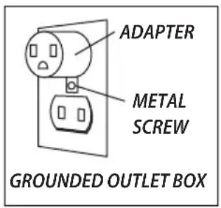
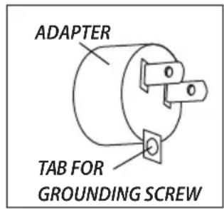
Sketch CSketch B
IN CANADA, THE USE OF A TEMPORARY ADAPTER IS NOT PERMITTED BY THE CANADIAN ELECTRICAL CODE. Make sure that the appliance is connected to an outlet having the same configuration as the plug. No adapter should be used with this appliance.
EXTENSION CORDS
When using the appliance at a distance where an extension cord becomes necessary, a 3-conductor grounding cord of adequate size must be used for safety, and to prevent loss of power and overheating. Use TABLE A to determine A.W.G. wire size required. To determine ampere rating of the vacuum, refer to nameplate located on motor housing.
Before using appliance, inspect power cord for loose or exposed wires and damaged insulation. Make any needed repairs or replacements before using the appliance. Use only three-wire outdoor extension cords, which have three-prong grounding-type plugs and three-pole receptacles which accept the extension cord's plug. When vacuuming liquids, be sure the extension cord connection does not come in contact with the liquid.
NOTE: STATIC SHOCKS ARE COMMON IN DRY AREAS OR WHEN THE RELATIVE HUMIDITY OF THE AIR IS LOW. THIS IS ONLY TEMPORARY AND DOES NOT AFFECT THE USE OF THE APPLIANCE. TO REDUCE THE FREQUENCY OF STATIC SHOCKS IN YOUR HOME, THE BEST REMEDY IS TO ADD MOISTURE TO THE AIR WITH A CONSOLE OR INSTALLED HUMIDIFIER.
| Volts | Total length of cord in feet | |||
| 120V | 25 50 | 100 | 150 | |
| Ampere Rating More Not More Than Than | AWG | |||
| 0 - 6 | 18 | 16 | 16 | 14 |
| 6 - 10 | 18 | 16 | 14 | 12 |
| 10 - 12 | 18 | 16 | 14 | 12 |
TABLE A
UNPACKING
Pull lid latches 6 in an outward motion and remove tank cover. Remove any accessories and literature that may have been packed in the vacuum tank.
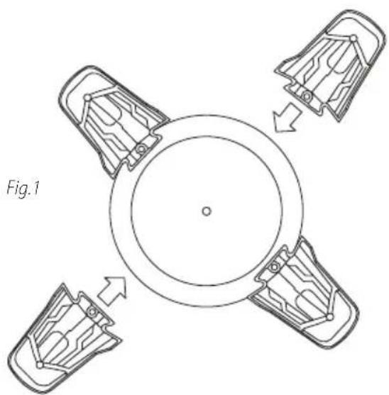
ASSEMBLY Caster System Assembly
You will find four casters 5, four caster feet 4 and four screws 9 with this wet/dry vacuum.
Assemble as follows:
- With cord disconnected from the receptacle and tank cover removed, turn tank upside-down so bottom is facing up.
- Take caster feet 4 and place into slots on tank. Fig. 1.
natural_image
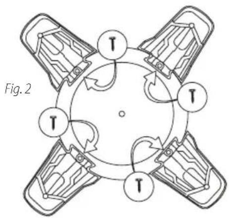
Top-down diagram of a circular mechanical component with four arms, showing internal structure and directional arrows (no text or symbols)- Secure caster feet 4 to tank with screws provided 9. Fig. 2.
flowchart
graph TD
    A["Arm 1"] --> B["Circle"]
    B --> C["Arm 2"]
    C --> D["Arm 3"]
    D --> E["Arm 4"]
    E --> F["Arm 5"]
    F --> G["Arm 6"]
    G --> H["Arm 7"]
    H --> I["Arm 8"]
    I --> J["Arm 9"]
    J --> K["Arm 10"]
    K --> L["Arm 11"]
    L --> M["Arm 12"]
    M --> N["Arm 13"]
    N --> O["Arm 14"]
    O --> P["Arm 15"]
    P --> Q["Arm 16"]
    Q --> R["Arm 17"]
    R --> S["Arm 18"]
    S --> T["Arm 19"]
    T --> U["Arm 20"]
    U --> V["Arm 21"]
    V --> W["Arm 22"]
    W --> X["Arm 23"]
    X --> Y["Arm 24"]
    Y --> Z["Arm 25"]
- Insert casters 5 into caster feet 4 by placing the caster stems into the holes provided. Apply pressure and twisting motion until casters 5 snap into place. Fig. 3.
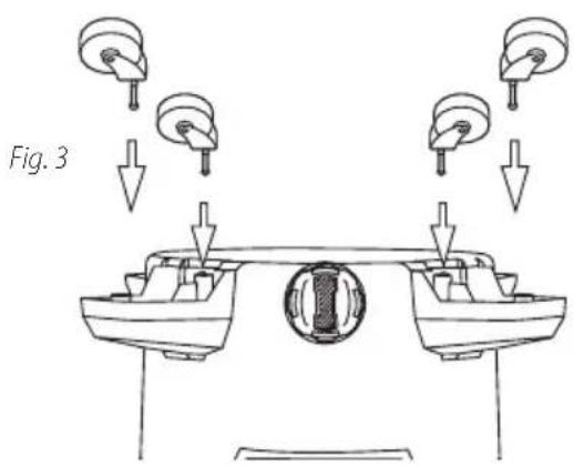
- Return tank to upright position.
GENERAL SET UP
- Before replacing tank cover, refer to Dry Pick Up or Wet Pick Up Operation in user manual to ensure you have the proper filters installed for this cleaning operation.
- Replace tank cover, and apply pressure with thumb to each lid latch 6 until it snaps tightly into place. Make certain all lid latches 6 are clamped securely.
- Insert hose 12 (hose end with locking-nut) into inlet of tank 2. Turn locking nut to tighten. Do not over-tighten.
- Attach the extension wands 11 to the accessory end of the hose 12. Twist slightly to tighten the connection. Fig. 4.
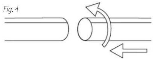
- Attach one of the cleaning accessories (depending on your cleaning requirements) on the extension wands 11. Twist slightly to tighten the connection. Fig. 4.
- Plug the cord 7 into the wall outlet. Your cleaner is ready for use. I = ON, O = OFF
FILTER INSTALLATION AND CLEAN UP Dry Pick Up Operation
NOTE: Never use the vacuum for dry pick up without a dry use filter installed on the lid cage. Using the vacuum without a filter will cause dust to discharge from blower port and cause damage to motor.
INSTALLING AND CLEANING THE CARTRIDGE FILTER 14, 15 :
WARNING: ALWAYS DISCONNECT THE PLUG FROM THE WALL OUTLET BEFORE REMOVING THE TANK COVER.
NOTE: If foam sleeve 16 is installed on lid cage, remove before installing the cartridge filter 14.
- The cartridge filter 14 can be used for dry pick up and small quantities of wet pick up. Installation is the same for both. When picking up large quantities of water we recommend using a foam sleeve 16 instead of the cartridge filter 14. When picking up fine dust or powders a high efficiency filter bag (not standard with all models) must be used with the cartridge filter.
NOTE: If cartridge filter 14 has been used for wet pick up, it must be cleaned and dried before using it for dry pick up.
ENGLISH
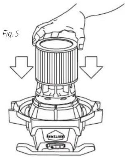
- With the tank cover in an upside down position, slide the cartridge filter 14 down over the lid cage, pushing until the filter seals against the cover. Fig. 5.
- Place filter retainer 15 into the top of the cartridge filter 14. Fig. 6.
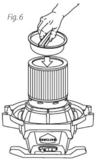
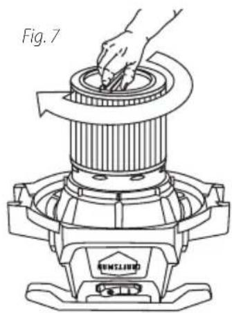
- Hold the tank cover with one hand, turn the handle on the filter retainer 15 clockwise to tighten, locking the cartridge filter 14 into place. Fig. 7.
natural_image
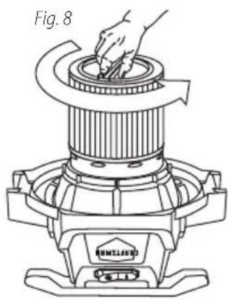
Line drawing of a hand using a tool to press down a cylindrical component, labeled Fig. 7 (no text or symbols on the diagram itself)- To remove the cartridge filter 14 for cleaning, again hold the tank cover and turn the filter retainer 15 counterclockwise to loosen and remove. Fig. 8.
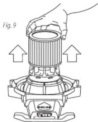
- Slide the cartridge filter 14 off the lid cage. Fig. 9.
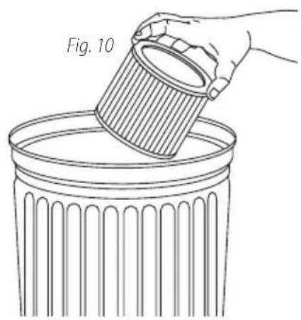
18 To clean cartridge filter 14 shake or brush off excess dirt. Fig. 10.
natural_image
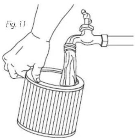
Line drawing of a hand pouring liquid into a trash bin (no text or symbols)- Or rinse (from the inside of the cartridge filter 14) with water. Fig. 11. Dry completely (approximately 24 hours).
natural_image
Illustration of a hand pouring liquid into a water tap (no text or symbols)INSTALLING FILTER BAG17:
Use the filter bag 17 in conjunction with the cartridge filter 14 for easy disposal of the debris. The filter bag 17 is not required for normal dry pick up. When picking up fine dust or powders a high efficiency filter bag (not standard with all models) must be used. NOTE: For dry use only.
WARNING: MAKE SURE THE CORD IS DISCONNECTED FROM THE RECEPTACLE, TANK COVER IS REMOVED AND THE HOSE IS DISCONNECTED FROM TANK INLET.
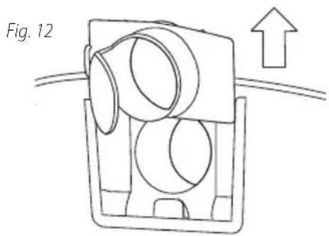
- Remove inlet deflector from deflector guide. NOTE: Hose 12 must be removed before inlet deflector can be taken out. Fig. 12.
natural_image
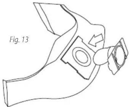
Diagram of a mechanical component with arrows indicating direction, no text or symbols present- With the opening of the inlet deflector facing the left or right side of the filter bag 17, slide filter bag collar 17 over deflector matching notches of bag collar to tabs on inlet deflector. Bag will only fit properly one way. Fig. 13.
natural_image
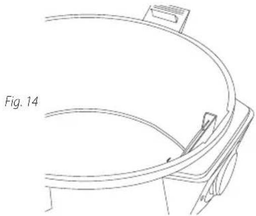
Line drawing of a mechanical component with a labeled section 'Fig. 13' (no other text or symbols)- Slide deflector with filter bag 17 attached into deflector guide. Fig. 14.
natural_image
Technical line drawing of a curved mechanical component with a labeled section 'Fig. 14' (no other text or symbols)-
Reinsert hose 12 into inlet and tighten locking-nut. When secured in place expand bag 17 and position around inside of tank.
-
NOTE: When removing filter bag 17 from tank, remove inlet deflector from filter bag collar and reinstall into deflector guide. Inlet deflector should always be in place for any type of cleaning.
WARNING: KEEP FILTERS CLEAN. EFFICIENCY OF THE VACUUM IS LARGELY DEPENDENT ON THE FILTER. A CLOGGED FILTER CAN CAUSE OVERHEATING AND POSSIBLY DAMAGE THE CLEANER. CHECK THE FILTER PERIODICALLY AND REPLACE AS REQUIRED.
WARNING: FOR FINE DUST
POWDERS
When vacuuming fine dust, or powders of any kind (plaster, drywall dust, cold ashes, concrete dust, etc.) a high efficiency drywall filter bag must be used. When vacuuming normal household dust and debris, standard household disposable filter bags may be used.
- Check the filter bag 17 for tears or small holes. If none are found, reinstall the filter bag 17. To prevent damage to this vacuum, do not use a filter bag 17 with a hole or a tear.
-
Your vacuum can be used for wet pick up. Remove ALL dirt and debris found in the tank. Remove all dry use only filters, including the filter bag 17, from this vacuum.
-
A clean cartridge filter 14 may be used to pick up small quantities of liquid. To use the cartridge filter 14; follow the cleaning and installation instructions under dry pick up.
-
For vacuuming large quantities of liquid use a foam sleeve 16. To use the foam sleeve 16; follow the installation instructions in this section.
ENGLISH
- Misting in the exhaust air or dripping of liquid around the tank cover may occur if the foam sleeve 16 becomes saturated during wet pick up. If this occurs, remove the foam sleeve 16 and allow to dry, or replace with another dry foam sleeve 16.
- Turn the unit off immediately upon completing a wet pick up job or when tank is full and ready to be emptied. When the tank is full, suction will drastically reduce. Refer to "automatic suction shut off" in this manual. Raise the hose 12 to drain any excess liquid into the tank. Follow the "emptying liquid waste" section in this manual.
- Before storing the vacuum cleaner or using for dry pick up, clean and dry the interior of the tank and the underside of the tank cover. Clean and allow the filters to dry completely.
NOTE: WET PICK UP ACCESSORIES SHOULD BE WASHED PERIODICALLY; ESPECIALLY AFTER PICKING UP WET, STICKY ACCIDENTS. THIS CAN BE ACCOMPLISHED WITH A WARM SOLUTION OF SOAP AND WATER.
FOAM SLEEVE 16 INSTALLATION AND CLEANING:
- With tank cover in an upside down position, slide foam sleeve 16 down over lid cage pulling until foam sleeve 16 completely covers lid cage. Fig. 15.

natural_image
Line drawing of hands operating a portable stove burner with arrows indicating downward motion (no text or symbols)WARNING: TO CLEAN THE FOAM SLEEVE, DISCONNECT THE PLUG FROM THE WALL OUTLET. REMOVE THE TANK COVER AND PLACE THE COVER IN AN UPSIDE-DOWN POSITION. REMOVE FOAM SLEEVE BY SLIDING IT UP AND OFF THE LID CAGE.
- Shake excess debris off of the foam sleeve 16 with a rapid up and down movement.
- Hold foam sleeve 16 under running water for a minute or two, rinsing from the inside of the foam sleeve 16. A water wash is not always required, depending on the condition of the foam sleeve 16.
- Check the foam sleeve 16 for tears. If any are found, replace with a new foam sleeve 16.
BLOWER FEATURE
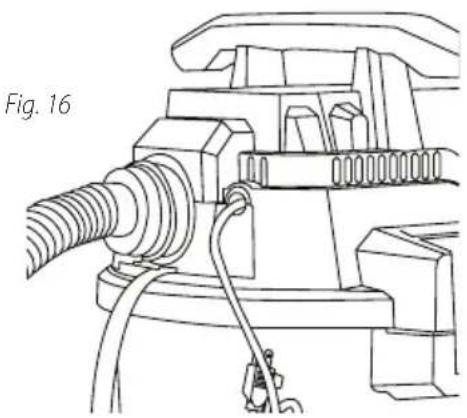
- The vacuum can be used as a powerful blower 3. Clear hose 12 of any obstructions. Insert machine hose end with locking nut into blower port 3 and tighten locking-nut. Fig. 16. Do not over-tighten. Caution should be used when using as a blower 3 due to the powerful force of air when using certain attachments.
natural_image
Technical line drawing of a mechanical assembly with hoses and connectors (no text or symbols)WARNING: ALWAYS WEAR EYE PROTECTION TO PREVENT ROCKS OR DEBRIS FROM BEING BLOWN OR RICOCHETING INTO THE EYES OR FACE WHICH CAN RESULT IN SERIOUS INJURY.
EMPTYING LIQUID WASTE FROM THE TANK
- Your wet/dry vacuum can be emptied of liquid waste by removing the drain cap 10. To empty, turn unit off and remove plug from the wall receptacle. Remove the drain cap 10. and deposit the liquid waste contents in a suitable drain. After the tank is empty, return the drain cap 10. to its original position. To continue use, plug the cord into the wall receptacle and turn the unit on. Use side carry handles for lifting vac when draining tank into drains that are located above floor level.
AUTOMATIC SUCTION SHUT-OFF
- The vacuum is equipped with an automatic suction shut-off that operates when picking up liquids. As the level of the liquid rises in the tank, an internal float rises until it seats itself against a seal at the intake of the motor, shutting off suction. When this happens, the motor will develop a higher than normal pitch noise and the suction is drastically reduced. If this occurs, turn unit off immediately. Failure to turn unit off after float rises and shuts off suction will result in extensive damage to the motor. To continue use, empty the liquid waste from the tank as outlined in the previous section.
NOTE: IF ACCIDENTALLY TIPPED OVER, THE VACUUM COULD LOSE SUCTION. IF THIS OCCURS, TURN UNIT OFF AND PLACE VAC IN UPRIGHT POSITION. THIS WILL ALLOW THE FLOAT TO RETURN TO ITS NORMAL POSITION, AND YOU WILL BE ABLE TO CONTINUE OPERATION.
LUBRICATION
- No lubrication is necessary as the motor is equipped with lifetime lubricated bearings.
TOOL STORAGE
-
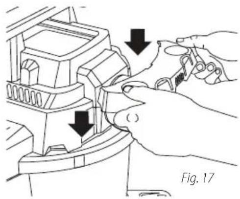
Set tank cover onto the tank. Position back of tank facing you.
-
Take tool holder 18 and slide over notches located on rear of tank. Fig. 17.
natural_image
Line drawing of hands operating a mechanical device with arrows indicating process steps (no text or symbols)HOSE STRAP 10
-
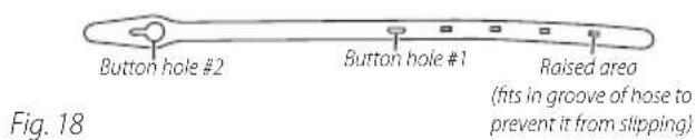
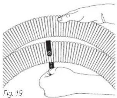
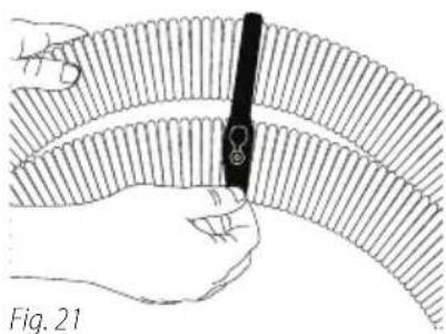
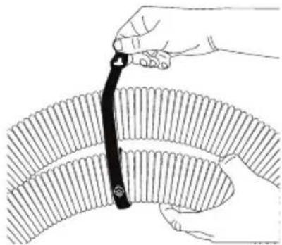
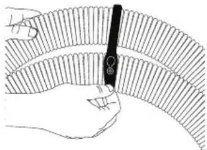
Wrap hose strap 19 .Fig. 18 around hose 12 aligning raised areas on back of strap 19 into a groove on hose 12 .Fig. 19.
-
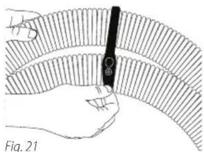
Insert button #1 into button hole #1 Fig. 19 (this may be difficult at first), continue to wrap hose strap 19 around hose 12. Fig. 20. Insert button #2 into button hole #2 Fig. 21.

natural_image
Illustration of a hand holding a pen inserted into a curved, ribbed material (no text or symbols)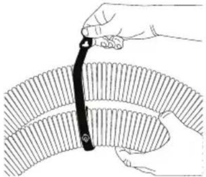
natural_image
Illustration of a hand using a tool to lift a curved object, no text or symbols presentFig. 20
natural_image
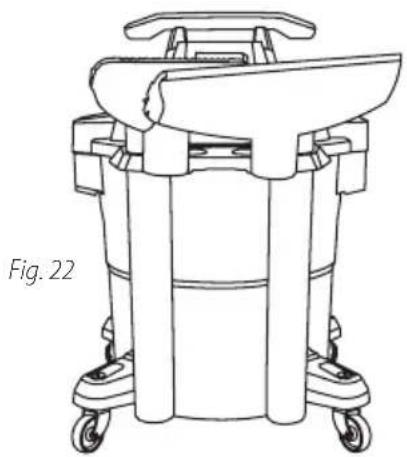
Illustration of a hand holding a pen inserted into a curved, ribbed material (no text or symbols)- Place vacuum tools in tool holder 18. Fig. 22. The vacuum should be stored indoors.
natural_image
Line drawing of a medical or laboratory apparatus with wheels and a central component (no text or symbols)Register Online
Thank you for your purchase. Register your product now for:
- WARRANTY SERVICE: Registering your product will help you obtain more efficient warranty service in case there is a problem with your product.
- CONFIRMATION OF OWNERSHIP: In case of an insurance loss, such as fire, flood or theft, your registration of ownership will serve as your proof of purchase.
• FOR YOUR SAFETY: Registering your product will allow us to contact you in the unlikely event a safety notification is required under the Federal Consumer Safety Act.
Register online at www.craftsman.com/registration
Three Year Limited Warranty
CRAFTSMAN will repair or replace, without charge, any defects due to faulty materials or workmanship for three years from the date of purchase. This warranty does not cover part failure due to normal wear or tool abuse. For further detail of warranty coverage and warranty repair information, visit www.craftsman.com or call 1-888-331-4569. This warranty does not apply to accessories or damage caused where repairs have been made or attempted by others. THIS LIMITED WARRANTY IS GIVEN IN LIEU OF ALL OTHERS, INCLUDING THE IMPLIED WARRANTY OF MERCHANTABILITY AND FITNESS FOR A PARTICULAR PURPOSE, AND EXCLUDES ALL INCIDENTAL OR CONSEQUENTIAL DAMAGES. Some states do not allow limitations on how long an implied warranty lasts or the exclusion or limitation of incidental or consequential damages, so these limitations may not apply to you. This
warranty gives you specific legal rights and you may have other rights which vary in certain states or provinces.
90 DAY MONEY BACK GUARANTEE
If you are not completely satisfied with the performance of your CRAFTSMAN Wet Dry Vacuum for any reason, you can return it within 90 days from the date of purchase with a receipt for a full refund – no questions asked.
LATIN AMERICA: This warranty does not apply to products sold in Latin America. For products sold in Latin America, see country specific warranty information contained in the packaging, call the local company or see website for warranty information.
FREE WARNING LABEL REPLACEMENT: If your warning labels become illegible or are missing, call 1-888-331-4569 for a free replacement.
TROUBLESHOOTING GUIDE
BE SURE TO FOLLOW SAFETY RULES AND INSTRUCTIONS
For assistance with your product, visit our website at www.craftsman.com for a list of service centers, or call CRAFTSMAN at 1-888-331-4569.
PROBLEM CAUSE CORRECTION
| Loss of suction wet pick up Clogged filter. Clean filter, see steps 16-19 on page 5 & 6. | |
| Full tank. Empty tank, see step 37 on page 7. | |
| Loss of suction dry pick up Full tank. Empty tank. | |
| Clogged filter. Clean filter, see steps 16-19 on pages 5 & 6. | |
| Loss of suction or misting Full tank. Drain and clean tank, see step 37 on page 7. | |
| during wet pick up Saturated filter. Clean filter, see step 29 on page 7. | |
*Tank capacity refers to actual tank volume, and does not reflect capacity available during operation.
natural_image
Top-down diagram of a circular mechanical component with four arms, showing internal structure and directional arrows (no text or symbols)natural_image
Line drawing of a hand placing a component into a bowl on a machine (no text or symbols)natural_image
Line drawing of a hand operating a cylindrical device with a base labeled 'UNSLUND', no text or symbols present.natural_image
Technical line drawing of a mechanical device with a hand operating the top component (no text or symbols)natural_image
Line drawing of a hand pouring liquid into a trash bin (no text or symbols)natural_image
Line drawing of a hand pouring liquid into a cylindrical container with a faucet (no text or symbols)natural_image
Diagram of a mechanical component with circular features and an upward arrow, labeled Fig. 12 (no text or symbols on the diagram itself)natural_image
Line drawing of a mechanical component with no visible text or symbolsnatural_image
Line drawing of a curved mechanical component with a clip, labeled Fig. 14 (no text or symbols on the diagram itself)natural_image
Line drawing of hands operating a portable stove with arrows indicating downward motion (no text or symbols)natural_image
Technical line drawing of a mechanical assembly with hoses and components (no text or symbols)natural_image
Line drawing of hands operating a mechanical device with arrows indicating process steps (no text or symbols)CORREA DE LA MANGUERA
natural_image
Illustration of a hand holding a tool interacting with a curved, ribbed material (no text or symbols)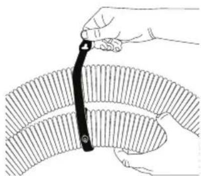
natural_image
Illustration of a hand using a tool to cut a curved mechanical component (no text or symbols visible)Fig. 20
natural_image
Illustration of a hand holding a pen inserted into a ribbed, segmented material (no text or symbols)natural_image
Line drawing of a medical or laboratory device with wheels and a curved top component (no text or symbols)natural_image
Diagram of four mechanical components arranged around a central circle, with arrows indicating rotation or movement (no text or symbols)I = EN MARCHE, O = À L'ARRÊT
natural_image
Line drawing of a hand pressing down on a mechanical component labeled 'Figure 6' (no text or symbols on the diagram itself)natural_image
Technical line drawing of a mechanical device with a hand operating the top component (no text or symbols)natural_image
Technical line drawing of a mechanical device with a hand operating the top component (no text or symbols)natural_image
Line drawing of a hand pouring liquid into a trash bin (no text or symbols)natural_image
Line drawing of a hand pouring liquid into a cylindrical container using a faucet (no text or symbols)INSTALLATION DU SAC-FILTRE17:
natural_image
Diagram of a mechanical component with labeled figure 12 and an upward arrow, no readable text or symbols present.natural_image
Line drawing of a mechanical component with labeled figure 13 (no text or symbols on the diagram itself)natural_image
Technical line drawing of a mechanical component with no visible text or symbolsnatural_image
Line drawing of hands operating a portable stove with arrows indicating downward motion (no text or symbols)AVERTISSEMENT :
POUR NETTOYER LE MANCHON DE MOUSSE, DÉBRANCHEZ LA FICHE DE LA PRISE MURALE. RETIREZ LE COUVERCLE DE LA CUVE ET METTEZ-LE À L'ENVERS. RETIREZ LE MANCHON DE MOUSSE EN LE FAISANT GLISSER HORS DU COUVERCLE PROTECTEUR.
natural_image
Technical line drawing of a mechanical assembly with hoses and components (no text or symbols)AVERTISSEMENT :
TOUJOURS PORTER DES LUNETTES DE PROTECTION POUR ÉVITER QUE DES PIERRES OU DES DÉBRIS NE SOIENT SOUFFLÉS DANS LES YEUX OU LE VISAGE OU LES ATTEIGNENT PAR RICOCHET.
VIDANGE DES DÉCHETS LIQUIDES DU CUVE
natural_image
Line drawing of a mechanical component with arrows indicating assembly or adjustment (no text or symbols)SANGLE
natural_image
Illustration of a hand holding a pen over a curved, ribbed material (no text or symbols)Fig. 19
natural_image
Illustration of a hand using a tool to cut a curved object, no text or symbols presentFig. 20
natural_image
Illustration of a hand holding a pen inserted into a curved, ribbed material (no text or symbols)Fig. 21
natural_image
Line drawing of a medical or laboratory device with wheels and a central handle (no text or symbols)Register online at www.craftsman.com/registration
PROBLÈME CAUSE CORRECTIF
Product Manufactured by: Shop-Vac Corporation
LICENSEE NAME: Shop Vac Corporation
LICENSEE ADDRESS: Williamsport, PA

- Definitions: Safety Alert Symbols and Words
- COMPONENTS
- CMXEVBCV1260L
- IMPORTANT SAFETY INSTRUCTIONS
- SAVE ALL WARNINGS AND INSTRUCTIONS FOR FUTURE REFERENCE
- GROUNDING INSTRUCTIONS
- WARNING: IMPROPER
- EXTENSION CORDS
- UNPACKING
- ASSEMBLY Caster System Assembly
- GENERAL SET UP
- FILTER INSTALLATION AND CLEAN UP Dry Pick Up Operation
- ENGLISH
- INSTALLING FILTER BAG17:
- POWDERS
- FOAM SLEEVE 16 INSTALLATION AND CLEANING:
- BLOWER FEATURE
- EMPTYING LIQUID WASTE FROM THE TANK
- AUTOMATIC SUCTION SHUT-OFF
- LUBRICATION
- TOOL STORAGE
- HOSE STRAP 10
- Register Online
- Three Year Limited Warranty
- DAY MONEY BACK GUARANTEE
- TROUBLESHOOTING GUIDE
- BE SURE TO FOLLOW SAFETY RULES AND INSTRUCTIONS
- CORREA DE LA MANGUERA
- INSTALLATION DU SAC-FILTRE17:
- AVERTISSEMENT :
- VIDANGE DES DÉCHETS LIQUIDES DU CUVE
- SANGLE
Brand : Craftsman
Model : CMXEVBCV1260L
Category : Vacuum Cleaner