
ULD410 - Detector Amprobe - Free user manual and instructions
Find the device manual for free ULD410 Amprobe in PDF.
| Product Type | Ultrasonic Leak Detector |
| Brand | Amprobe |
| Model | ULD410 (receiver kit ULD-400-R) |
| Receiver Dimensions | 183 x 75 x 43 mm |
| Receiver Weight | Approximately 235 g |
| Receiver Power Supply | 4 AA 1.5 V (LR6) alkaline batteries |
| Frequency Range | 20 kHz to 90 kHz |
| Digital Filter | Up to 3 frequencies, bandwidth ±5 kHz |
| Display | 2.5-inch TFT LCD (262K colors) |
| Display Type | Digital signal intensity and histogram |
| Audio Output | 3.5 mm jack for headphones (included) |
| Battery Life (receiver) | Approximately 105 hours (alkaline) |
| Operating Temperature | -20 °C to 50 °C |
| Protection Rating | IP40 |
| Included Accessories | Headphones, earbuds, parabola PB-1, flexible tube adapter TEA-1, tubular extension TE-1, carrying case, 4 AA batteries |
| Maintenance | Clean exterior with a neutral water and detergent solution; replace batteries if necessary |
| Safety | Do not use on explosive gases; caution near pressurized air/gas, rotating or electrical equipment |
| Repairability | 1-year warranty; repairs by Amprobe authorized center; user-replaceable batteries |
Frequently Asked Questions - ULD410 Amprobe
User questions about ULD410 Amprobe
0 question about this device. Answer the ones you know or ask your own.
Ask a new question about this device
Download the instructions for your Detector in PDF format for free! Find your manual ULD410 - Amprobe and take your electronic device back in hand. On this page are published all the documents necessary for the use of your device. ULD410 by Amprobe.
USER MANUAL ULD410 Amprobe
Limited Warranty and Limitation of Liability
Your Amprobe product will be free from defects in material and workmanship for one year from the date of purchase unless local laws require otherwise. This warranty does not cover fuses, disposable batteries or damage from accident, neglect, misuse, alteration, contamination, or abnormal conditions of operation or handling. Resellers are not authorized to extend any other warranty on the behalf of Amprobe. To obtain service during the warranty period, return the product with proof of purchase to an authorized Amprobe Service Center or to an Amprobe dealer or distributor. See Repair Section for details. THIS WARRANTY IS YOUR ONLY REMEDY. ALL OTHER WARRANTIES - WHETHER EXPRESS, IMPLIED OR STATUTORY - INCLUDING IMPLIED WARRANTIES OF FITNESS FOR A PARTICULAR PURPOSE OR MERCHANTABILITY, ARE HEREBY DISCLAIMED. MANUFACTURER SHALL NOT BE LIABLE FOR ANY SPECIAL, INDIRECT, INCIDENTAL OR CONSEQUENTIAL DAMAGES OR LOSSES, ARISING FROM ANY CAUSE OR THEORY. Since some states or countries do not allow the exclusion or limitation of an implied warranty or of incidental or consequential damages, this limitation of liability may not apply to you.
Repair
All Amprobe returned for warranty or non-warranty repair or for calibration should be accompanied by the following: your name, company's name, address, telephone number, and proof of purchase. Additionally, please include a brief description of the problem or the service requested and include the test leads with the meter. Non-warranty repair or replacement charges should be remitted in the form of a check, a money order, credit card with expiration date, or a purchase order made payable to Amprobe.
In-warranty Repairs and Replacement – All Countries
Please read the warranty statement and check your battery before requesting repair. During the warranty period, any defective test tool can be returned to your Amprobe distributor for an exchange for the same or like product. Please check the "Where to Buy" section on amprobe.com for a list of distributors near you. Additionally, in the United States and Canada, in-warranty repair and replacement units can also be sent to an Amprobe Service Center (see address below).
Non-warranty Repairs and Replacement – United States and Canada
Non-warranty repairs in the United States and Canada should be sent to an Amprobe Service Center. Call Amprobe or inquire at your point of purchase for current repair and replacement rates.
USA: Canada:
Amprobe
Amprobe
Everett, WA 98203
Mississauga, ON L4Z 1X9
Tel: 877-AMPROBE (267-7623)
Tel: 905-890-7600
Non-warranty Repairs and Replacement – Europe
European non-warranty units can be replaced by your Amprobe distributor for a nominal charge. Please check the "Where to Buy" section on beha-amprobe.com for a list of distributors near you.
Beha-Amprobe*
In den Engematten 14
79286 Glottertal, Germany
Tel.: +49 (0) 7684 8009 - 0
beha-amprobe.com
*(Correspondence only – no repair or replacement available from this address. European customers please contact your distributor.)
CONTENTS
- PRECAUTIONS AND SAFETY MEASURES ...... 2
- INTRODUCTION .... 3
- KIT COMPONENTS......4
3.1 Kit Components ....4
3.2 ULD-400-R Receiver 5
3.3 ULD-400-T Transmitter 6
3.4 Accessories 7
- MAIN APPLICATIONS ....8
4.1 Using the ULD-400-R Ultrasonic Leak Detector Receiver 8
4.2 Using the ULD-400-T Ultrasonic Leak Detector Transmitter 10
- MAINTENANCE....11
5.1 Changing the Receiver Batteries .... 11
5.2 Changing the Transmitter Batteries 12
5.3 Cleaning 12
- SPECIFICATIONS ...... 13
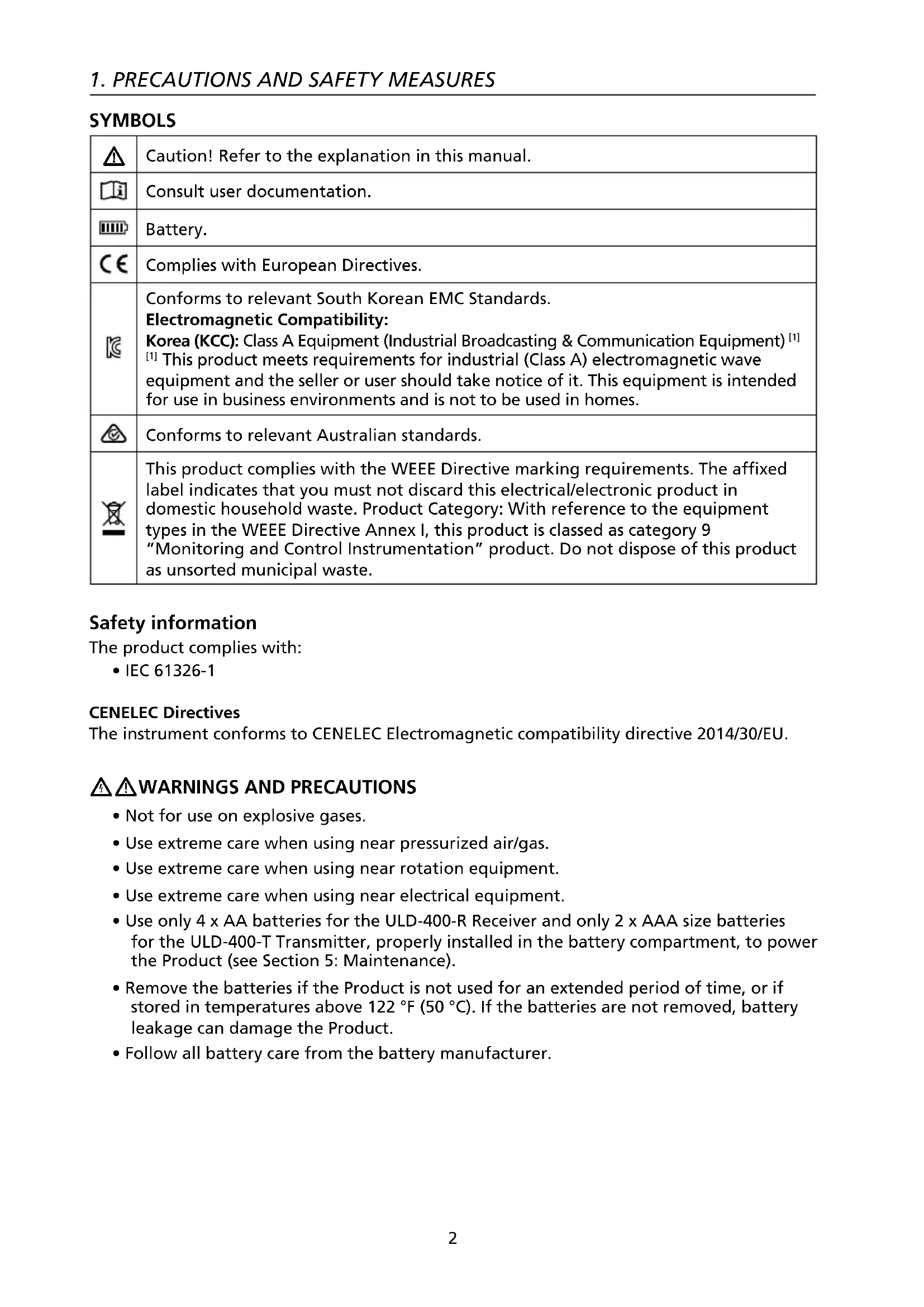
SYMBOLS
| [5ST8] | Caution! Refer to the explanation in this manual. |
 | Consult user documentation. |
 | Battery. |
 | Complies with European Directives. |
 | Conforms to relevant South Korean EMC Standards.Electromagnetic Compatibility:Korea (KCC): Class A Equipment (Industrial Broadcasting & Communication Equipment) [1][1] This product meets requirements for industrial (Class A) electromagnetic wave equipment and the seller or user should take notice of it. This equipment is intended for use in business environments and is not to be used in homes. |
| [YYBD] | Conforms to relevant Australian standards. |
| [04KZ] | This product complies with the WEEE Directive marking requirements. The affixed label indicates that you must not discard this electrical/electronic product in domestic household waste. Product Category: With reference to the equipment types in the WEEE Directive Annex I, this product is classed as category 9“Monitoring and Control Instrumentation” product. Do not dispose of this product as unsorted municipal waste. |
Safety information
The product complies with:
- IEC 61326-1
CENELEC Directives
The instrument conforms to CENELEC Electromagnetic compatibility directive 2014/30/EU.

⚠️ WARNINGS AND PRECAUTIONS
- Not for use on explosive gases.
- Use extreme care when using near pressurized air/gas.
- Use extreme care when using near rotation equipment.
- Use extreme care when using near electrical equipment.
- Use only 4 x AA batteries for the ULD-400-R Receiver and only 2 x AAA size batteries for the ULD-400-T Transmitter, properly installed in the battery compartment, to power the Product (see Section 5: Maintenance).
- Remove the batteries if the Product is not used for an extended period of time, or if stored in temperatures above 122 °F (50 °C). If the batteries are not removed, battery leakage can damage the Product.
- Follow all battery care from the battery manufacturer.
2. INTRODUCTION
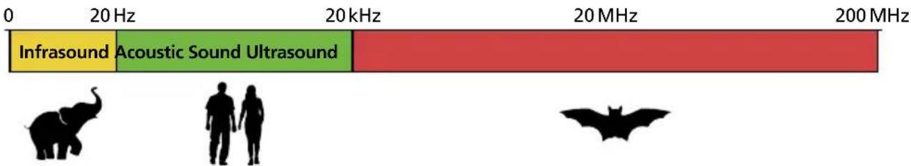
Ultrasonic sound, or ultrasound, is a sound wave with frequencies above 20 kHz, higher than the upper audible limit of human hearing. Ultrasound can be generated when turbulence created by air or gas is forced through a small orifice. Leaking air or gas is generally considered to be viscous flow, and as the flow velocity increases, the frequency of the ultrasound emitted becomes higher. Vibrating, moving objects or electric discharge will also create an ultrasonic wave, which is very directional in nature and can be used to pinpoint the exact location of a leak, vibration or discharge.
The ULD-400-R Receiver detects ultrasounds within 20 kHz to 90 kHz frequency, then amplifies and converts these ultrasonic sounds to frequencies and levels that the human ear can hear through headphones and show it on the LCD screen. The 20 kHz to 90 kHz frequency range is the optimal range for detecting a variety of leakage events in assets such as HVAC systems and pneumatic lines. A change in the ultrasound produced by an asset may be indicative that an asset is beginning to fail.
line
| Frequency Range | Infrasound | Acoustic Sound Ultrasound | | --------------- | ---------- | -------------------------- | | 0 - 20 Hz | Green | Red | | 20 - 20 kHz | Green | Red | | 20 - 20 MHz | Red | Red | | 20 - 200 MHz | Red | Red |Figure 2: Sound range spectrum
3.1 Kit Components
Your shipping box should include:
| ULD-410 ULD-420 | |
| ULD-400-R Receiver 1 1 | |
| ULD-400-T Transmitter - 1 | |
| Headphones 1 1 | |
| Earbuds (for use with hard hat) 1 1 | |
| PB-1 Power Parabola 1 1 | |
| TEA-1 Flexible Tubing Adapter 1 1 | |
| TE-1 Tubular Extension 1 1 | |
| CC-ULD-400 Hard Carrying Case 1 1 | |
| AA Batteries (Receiver) 4 4 | |
| AAA Batteries (Transmitter) - 2 | |
| Manual 1 1 |
Note: Batteries are not pre-installed in the Receiver or Transmitter.
3.2 ULD-400-R Receiver
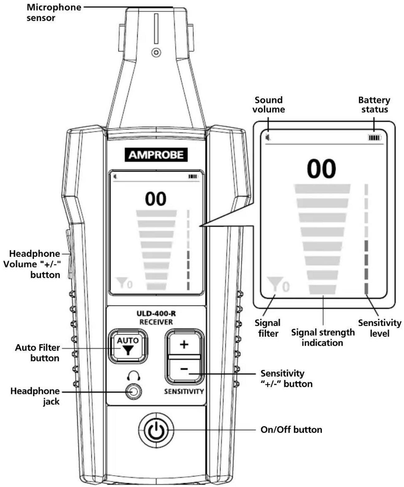
Figure 3.2: ULD-400-R Receiver
3.3 ULD-400-T Transmitter
The ULD-400-T Transmitter is included with the ULD-420 kit and is optional for the ULD-410 kit.
When a leak is not pressurized sufficiently the Receiver will not be able to detect it. In these circumstances, the ULD-400-T Transmitter can be used to emit an ultrasonic sound that the Receiver can read. The Transmitter is programmed with three signal levels for precise pinpointing of leaks.
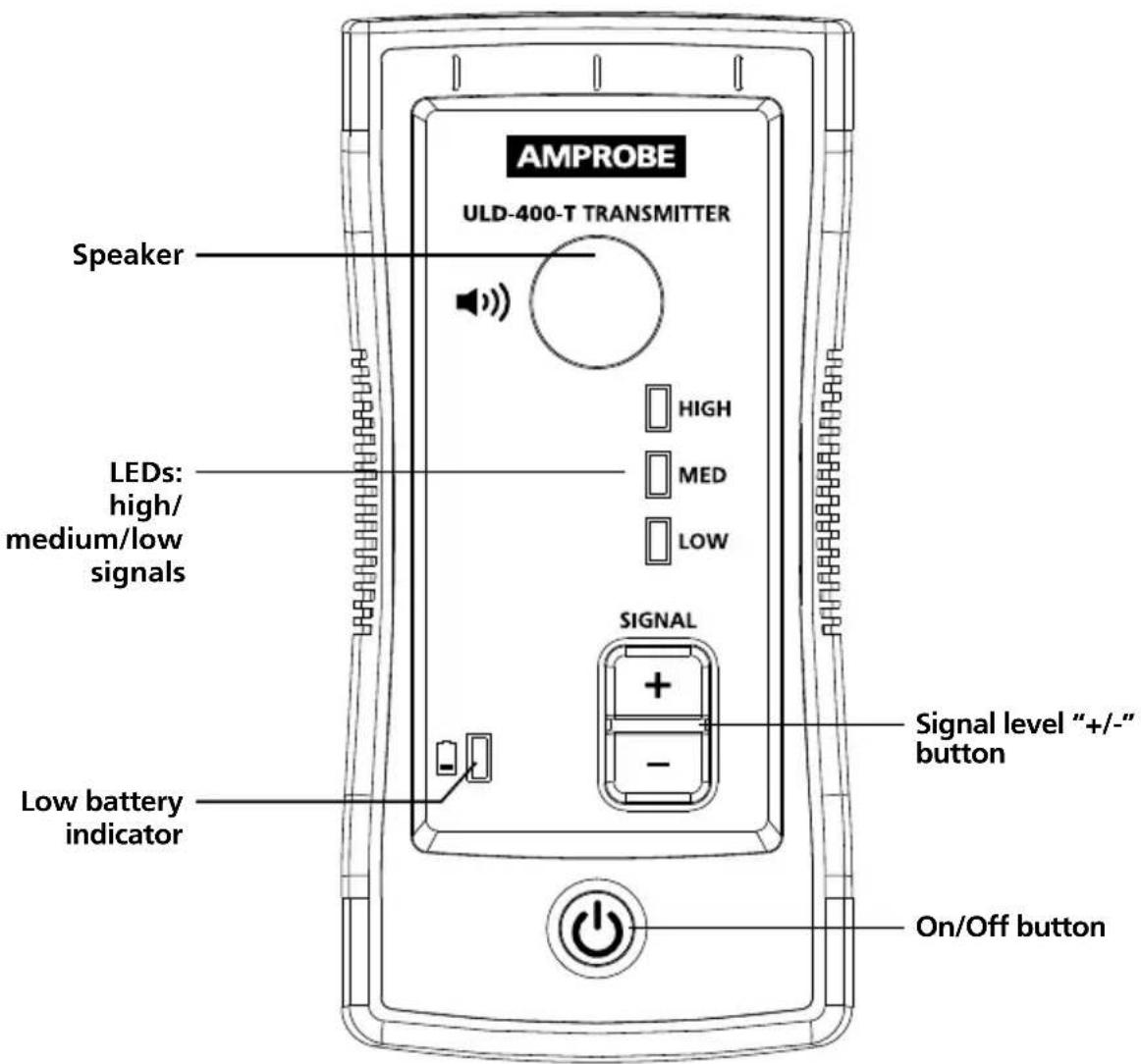
Figure 3.3: ULD-400-T Transmitter
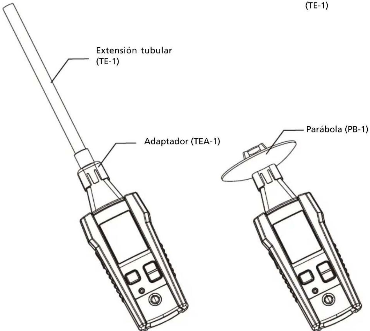
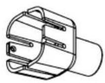
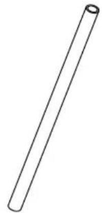
3.4 Accessories
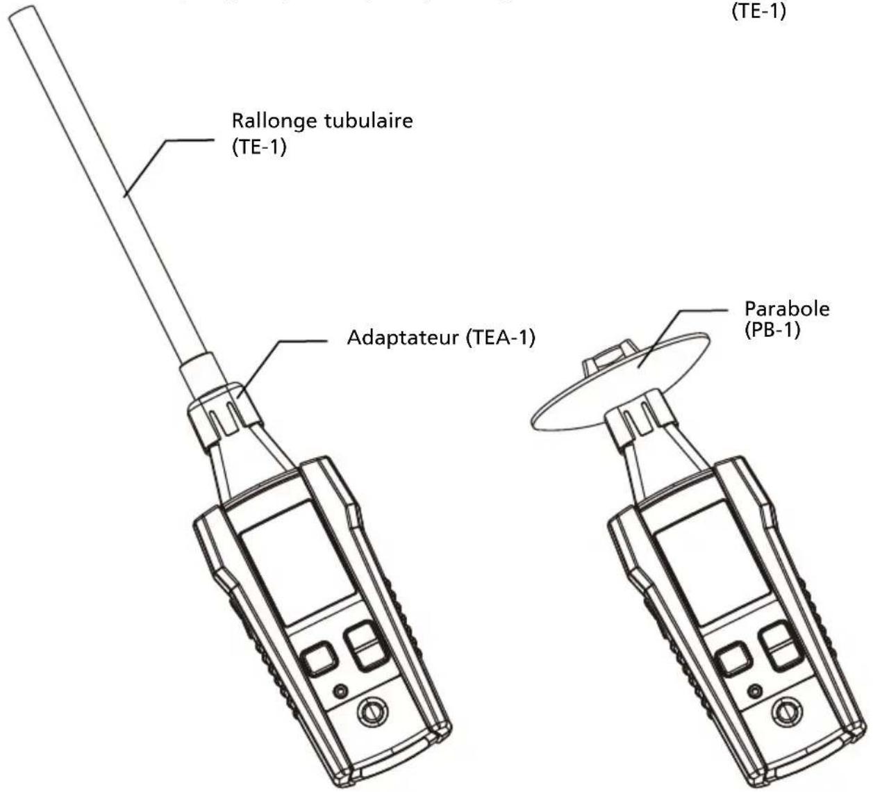
The ULD-400 comes supplied with additional Receiver accessories that are helpful in leak identification. Plug the headphones into the Receiver to audibly hear the leak and verify its source (for example hissing sound of an air leak versus ticking sound of an electric discharge). Use the Parabola attachment in situations where there is a high level of background noise to help direct the ultrasound towards the sensor. Use the Tubular Extension with the Adapter in hard to reach areas for additional reach.
Note: There is no speaker on the Receiver. Without headphones, no noise will be audible.
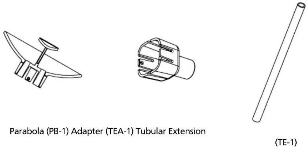
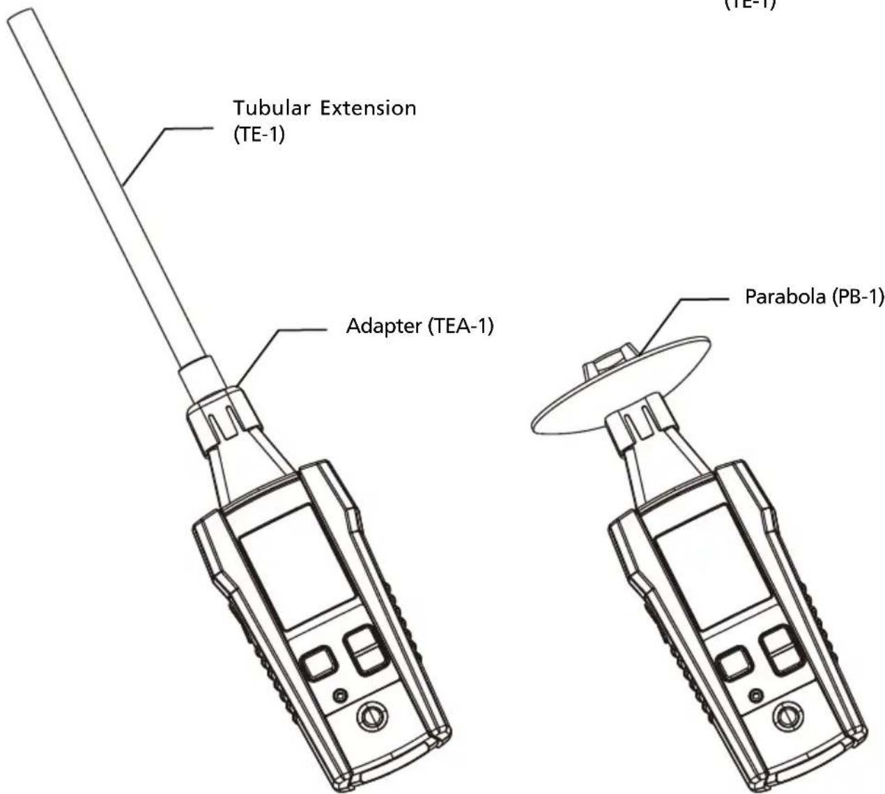
Figure 3.4: ULD-400 Accessories
4.1 Using the ULD-400-R Ultrasonic Leak Detector Receiver
- Turn on the Receiver and plug the headphones into the jack located on the front of the Receiver. Any standard set of 3.5 mm jack headphones are compatible.
- Before moving to the target area, press "+" or "-" sensitivity buttons to adjust signal strength sensitivity to the highest possible level where bargraph still shows either 0 or a value close to 0. If signal strength cannot be adjusted down and the LCD still shows a maximum value regardless on sensitivity adjustments, press the Filter button.*
- Scan the target area with the microphone sensor.
- As you move nearer to the source of the leak, vibration or electric discharge, the signal strength will increase. This will be indicated on a screen with increasing signal strength number and level of the bargraph.
- The bargraph is a relative measurement only, so when the signal strength reaches maximum, lower the sensitivity by pressing the "-" sensitivity button until the displayed signal strength is less than 75. Repeat this process until you have isolated the source of the ultrasound.
- The audible sound emitted via headphones will help to verify the source of the leak, for example hissing sound of the air leak versus ticking sound of the electric discharge. The Receiver screen alone will not provide an indication of the leak source.
Note:
- For surroundings with a high level of background noise use the Parabola (PB-1) to direct the ultrasound towards the sensor.
- For locations that you cannot point the Receiver directly at the leak, the Tubular Extension can be used (TE-1 with the TEA-1 Adapter).
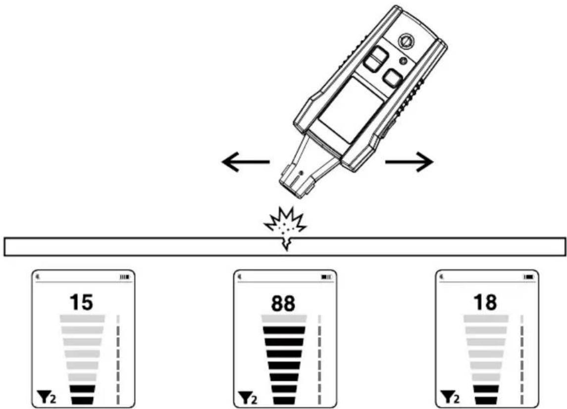
Figure 4.1a: Using the Receiver to find a leak
\*ULD-400-R Filter Operation
In some situations, there might be strong ultrasonic noise generated by running machinery, motion sensors or other equipment. This noise will cause the Receiver to read the maximum signal strength on the display regardless of the sensitivity settings and make it unusable for detecting leaks.
In such cases, press the "Filter" button. The firmware will automatically detect the main noise frequency and filter it out by applying digital non-pass bandwidth filter within +/- 5 kHz. If the signal level does not decrease down close to 0, then the firmware will automatically repeat the process for other noise frequencies. Up to three frequencies can be filtered out automatically. The filter icon will be displayed on the screen and will indicate the number of filters applied, from zero (no noise detected) to a maximum of three.
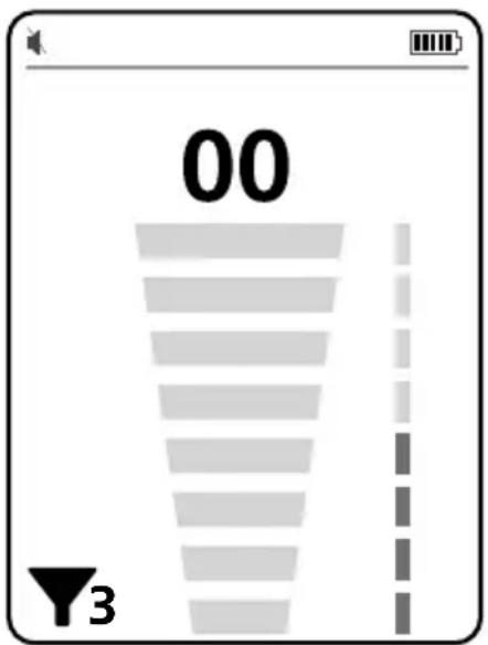
Figure 4.1b: Filter applied
Note: The filter will be applied to the visual signal indication on a screen (signal strength number and bargraph). The filter will NOT be applied to the audio frequency in order to preserve original sound of the leak and allow the user to better determine the source of the leak.
Note: When working with the Transmitter, make sure to apply the filter on the Receiver before the Transmitter is turned on, or in an area where the Transmitter signal can not be detected. Otherwise, the Transmitter signal frequency will be filtered out and Receiver will not be able to pick it up.
4.2 Using the ULD-400-T Ultrasonic Leak Detector Transmitter
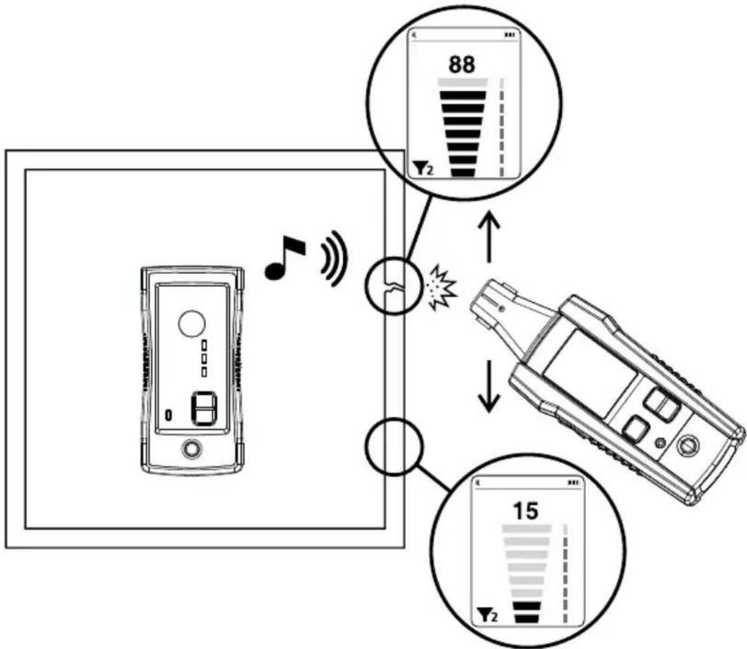
The Transmitter allows for ultrasonic detection of openings in locations where there is no gas or air pressure, or the pressure is not sufficient to detect the leak with the Receiver alone.
Typical applications include verifying tightness or pinpointing places of air, water or gas leaks in:
- Fluid or gas tanks
• Building windows, doors or roofs
• Car windows and windshields - HVAC vents
• Refrigerant pipelines
The process involves placing the Transmitter inside an object (such as tank, house or a car), sealing the entryways and scanning the object from the outside with the Receiver to verify tightness and pinpoint potential leaks.
- Turn on the Transmitter.
- Select the output signal level using the "+" or "-" signal level adjustment buttons.
Note: High setting is the default setting. For most applications and specifically for large objects this setting is particularly useful. The High signal may cause the Receiver to read maximum value away from the place of the leak even when lowest sensitivity was selected. Press "-" once to get to Medium signal and press "-" again to get to Low signal strength. Adjust signal level to allow for more precise pinpointing of the leaks. - Place the Transmitter inside the object to be verified and make sure entryways are sealed.
- Preform leak detecting with the Receiver as described in section 4.1.
flowchart
graph TD
    A["Device with antenna"] -->|Signal| B["Display Screen"]
    B --> C["Mobile Phone with Display Screen"]
    C --> D["Mobile Phone with Display Screen"]
    style A fill:#f9f,stroke:#333
    style B fill:#ccf,stroke:#333
    style C fill:#cfc,stroke:#333
    style D fill:#fcc,stroke:#333
Figure 4.2: Using the Transmitter and Receiver to find a leak
5.1 Changing the Receiver Batteries
The ULD-400-R uses four 1.5 V AA (LR6) batteries (supplied). To replace the batteries, follow these steps:
- Make sure that the Receiver is turned off.
- Use a screw driver to unscrew the captive screw.
-
Remove the battery cover.
-
Replace the batteries as shown in Figure 5.1. Observe the battery polarity shown in the battery compartment.
-
Replace the battery cover and secure it with the provided screw.
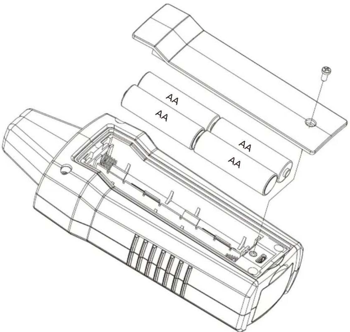
Figure 5.1: Changing the Receiver batteries
5.2 Changing the Transmitter Batteries
The ULD-400-T uses two 1.5 V AAA (LR03) batteries (supplied with ULD-420). To replace the batteries, follow these steps:
- Make sure that the Transmitter is turned off.
- Loosen the battery-door lock with a flat screwdriver.
- Remove the battery cover.
- Replace the batteries as shown in Figure 5.2. Observe the battery polarity shown in the battery compartment.
- Replace the battery cover to the lock position.
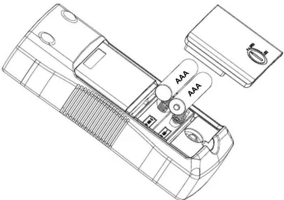
Figure 5.2: Replacing the Transmitter batteries
5.3 Cleaning
The only maintenance the ULD-400 requires is inspection and cleaning. Periodically wipe the exterior with a mild solution of detergent and water. Apply sparingly with a soft cloth and allow to dry completely before using. Do not use aromatic hydrocarbons, gasoline or chlorinated solvents for cleaning.
| Features ULD-400-R ULD-400-T | ||
| Sensitivity Adjustment Yes | N/A | |
| Volume Adjustment Yes N/A | ||
| Signal Level Adjustment N/A Yes | ||
| Earphone Jack | Yes(compatible with 3.5 mm audio jack) | N/A |
| Display Size LCD 2.5 in (6.35 cm) N/A | ||
| Display Dimensions 1.45 x | 1.93 in (36.72 x 48.96 mm) N/A | |
| Display Resolution 240(RGB) x 320 pixels N/A | ||
| Display Type | TFT-LCD (262 K) | N/A |
| Display Color | True, 16bit/color | N/A |
| Frequency Range | 20 kHz to 90 kHz | Typical 40 kHz squarewave |
| Filter | ±5 KHz of main noise frequency,up to three filters | N/A |
| Power Supply | 4 x 1.5 V AA (LR6) alkaline batteries | 2 x 1.5 V AAA (LR03) alkaline batteries |
| Power Consumption(typical) | 75 mA | 33 mA |
| Battery Life (typical) | 105 hours (Alkaline) | 60 hours (Alkaline) |
| Low battery indication | ### | Yes (Red LED) |
| APO function | 60 minutes when in idle | 60 minutes when in idle |
| Weight | Approx. 0.518 lb (0.235 kg) | Approx. 0.335 lb (0.152 kg) |
| Dimensions | 7.547 x 2.984 x 1.791 in(183 x 75 x 43 mm) | 5.295 x 2.559 x 1.326 in(137 x 65 x 33 mm) |
| Operating Temperature | -4 °F to 122 °F (-20 °C to 50 °C) | |
| Storage Temperature -4 °F | to 158 °F (-20 °C to 70 °C) | |
| Operating Humidity | <80% RH | |
| Pollution Degree | 2 | |
| Protection | IP40 | |
| Certifications | CE | |
| Electromagnetic Compatibility (EMC) | EN 61326-1Korea (KCC): Class A Equipment (Industrial Broadcasting & Communication Equipment)[1][1] This product meets requirements for industrial (Class A) electromagnetic wave equipment and the seller or user should take notice of it. This equipment is intended for use in business environments and is not to be used in homes. | |
ULD-400
- PRINCIPALES APPLICATIONS ....8
natural_image
Simple line drawing of a mechanical component with a curved base and central knob (no text or symbols)

natural_image
Simple line drawing of a cylindrical rod or tube with a circular end (no text or symbols)Parabole (PB-1) Adaptateur (TEA-1) Rallonge tubulaire
(TE-1)
natural_image
Three technical line drawings of mechanical components: a curved blade, a cylindrical housing with internal brackets, and a long rod (no text or symbols)Parábola (PB-1) Adaptador (TEA-1) Extensión tubular
(TE-1)
natural_image
Simple line drawing of a curved mechanical component with a knob and two supporting legs (no text or symbols)抛物面接收器(PB-1)
适配器 (TEA-1)
natural_image
Simple line drawing of a cylindrical rod or tube with a circular end (no text or symbols)管道延长接收器(TE-1)
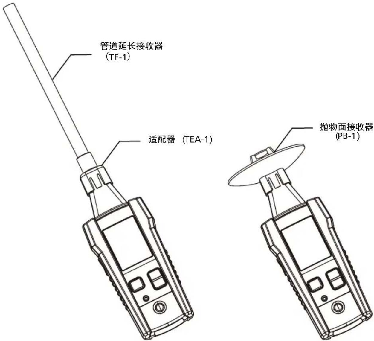
图4.1a: 采用接收器来寻找泄漏处
\*ULD-400-R过滤器操作
flowchart
graph TD
    A["Device with antenna"] -->|Signal| B["Display Screen"]
    B --> C["Mobile Phone with Display Screen"]
    C --> D["Mobile Phone with Display Screen"]
    style A fill:#f9f,stroke:#333
    style B fill:#ccf,stroke:#333
    style C fill:#cfc,stroke:#333
    style D fill:#fcc,stroke:#333
图5.1: 更换接收器电池
5.2 更换发送器电池
Visit amprobe.com for
- Catalog
- Application notes
• Product specifications - User manuals
Amprobe®
amprobe.com
Division of Fluke Corp.
6920 Seaway Blvd.
M/S 143F
Everett, WA 98203 USA
Tel: 877-AMPROBE (267-7623)
Beha-Amprobe®
beha-amprobe.com
c/o Fluke Europe BV
Science Park
Eindhoven 5110
NL-5692 EC Son
Tel.: +49 (0) 7684 8009 - 0

Please Recycle


- Limited Warranty and Limitation of Liability
- Repair
- In-warranty Repairs and Replacement – All Countries
- Non-warranty Repairs and Replacement – United States and Canada
- Non-warranty Repairs and Replacement – Europe
- CONTENTS
- Safety information
- CENELEC Directives
- ⚠️ WARNINGS AND PRECAUTIONS
- INTRODUCTION
- Kit Components
- ULD-400-R Receiver
- ULD-400-T Transmitter
- Accessories
- Using the ULD-400-R Ultrasonic Leak Detector Receiver
- Note:
- \*ULD-400-R Filter Operation
- Using the ULD-400-T Ultrasonic Leak Detector Transmitter
- Changing the Receiver Batteries
- Changing the Transmitter Batteries
- Cleaning
- ULD-400
- \*ULD-400-R过滤器操作
- 更换发送器电池
- Visit amprobe.com for
- Amprobe®
- Beha-Amprobe®
Brand : Amprobe
Model : ULD410
Category : Detector