
ALC110 - Electric multimeter Amprobe - Free user manual and instructions
Find the device manual for free ALC110 Amprobe in PDF.

| Product Type | Leakage Current Clamp Meter |
| Brand / Model | Amprobe ALC110 |
| Dimensions (H x W x D) | 221 x 89 x 48 mm |
| Weight (with batteries) | Approx. 410 g |
| Power Supply | 2 AAA 1.5 V batteries (LR03) |
| Display | 6000-count LCD, auto-backlight |
| Jaw Opening | 30 mm max |
| AC Measurement Ranges | 6 mA, 60 mA, 600 mA, 6 A, 60 A |
| Maximum Resolution | 0.001 mA |
| Basic Accuracy (50-60 Hz) | ±1.0% of reading + 5 digits |
| Frequency Response | 15 Hz to 1 kHz |
| Main Functions | True RMS, Max hold, Data hold, Limit, Filter (Device / 50-60 Hz), Auto power off |
| Safety | CAT III 600 V, double insulation, IP20 |
| Standards | IEC/EN 61010-1, 61010-2-032, 61557-13 |
| Operating Temperature | 0 °C to 50 °C (depending on RH) |
| Storage Temperature | -20 °C to 60 °C (without batteries) |
| Max Altitude | 2000 m |
| Battery Life | Approx. 60 hours |
| Maintenance | Clean jaws, calibration recommended every 1 to 3 years |
| Package Contents | ALC110 clamp, 2 AAA batteries, user manual, soft carrying case |
Frequently Asked Questions - ALC110 Amprobe
User questions about ALC110 Amprobe
0 question about this device. Answer the ones you know or ask your own.
Ask a new question about this device
Download the instructions for your Electric multimeter in PDF format for free! Find your manual ALC110 - Amprobe and take your electronic device back in hand. On this page are published all the documents necessary for the use of your device. ALC110 by Amprobe.
USER MANUAL ALC110 Amprobe
Leakage Current Clamp
User Manual
Limited Warranty and Limitation of Liability
Your Amprobe product will be free from defects in material and workmanship for one year from the date of purchase unless local laws require otherwise. This warranty does not cover fuses, disposable batteries or damage from accident, neglect, misuse, alteration, contamination, or abnormal conditions of operation or handling. Resellers are not authorized to extend any other warranty on the behalf of Amprobe. To obtain service during the warranty period, return the product with proof of purchase to an authorized Amprobe Service Center or to an Amprobe dealer or distributor. See Repair Section for details. THIS WARRANTY IS YOUR ONLY REMEDY. ALL OTHER WARRANTIES - WHETHER EXPRESS, IMPLIED OR STATUTORY - INCLUDING IMPLIED WARRANTIES OF FITNESS FOR A PARTICULAR PURPOSE OR MERCHANTABILITY, ARE HEREBY DISCLAIMED. MANUFACTURER SHALL NOT BE LIABLE FOR ANY SPECIAL, INDIRECT, INCIDENTAL OR CONSEQUENTIAL DAMAGES OR LOSSES, ARISING FROM ANY CAUSE OR THEORY. Since some states or countries do not allow the exclusion or limitation of an implied warranty or of incidental or consequential damages, this limitation of liability may not apply to you.
Repair
All Amprobe returned for warranty or non-warranty repair or for calibration should be accompanied by the following: your name, company's name, address, telephone number, and proof of purchase. Additionally, please include a brief description of the problem or the service requested and include the test leads with the meter. Non-warranty repair or replacement charges should be remitted in the form of a check, a money order, credit card with expiration date, or a purchase order made payable to Amprobe.
In-warranty Repairs and Replacement – All Countries
Please read the warranty statement and check your battery before requesting repair. During the warranty period, any defective test tool can be returned to your Amprobe distributor for an exchange for the same or like product. Please check the "Where to Buy" section on amprobe.com for a list of distributors near you. Additionally, in the United States and Canada, in-warranty repair and replacement units can also be sent to an Amprobe Service Center (see address below).
Non-warranty Repairs and Replacement – United States and Canada
Non-warranty repairs in the United States and Canada should be sent to an Amprobe Service Center. Call Amprobe or inquire at your point of purchase for current repair and replacement rates.
USA: Canada:
Amprobe
Amprobe
Everett, WA 98203 Mississauga, ON L4Z 1X9
Tel: 877-AMPROBE (267-7623) Tel: 905-890-7600
Non-warranty Repairs and Replacement – Europe
European non-warranty units can be replaced by your Beha-Amprobe distributor for a nominal charge. Please check the "Where to Buy" section on beha-amprobe.com for a list of distributors near you.
Beha-Amprobe
Division and reg. trademark of Fluke Corp. (USA)
Germany* United Kingdom
In den Engematten 14 52 Hurricane Way
79286 Glottertal Norwich, Norfolk
Germany NR6 6JB United Kingdom
Phone: +49 (0) 7684 8009 - 0 Phone: +44 (0) 1603 25 6662
beha-amprobe.de
beha-amprobe.com
The Netherlands - Headquarters**
Science Park Eindhoven 5110
5692 EC Son
The Netherlands
Phone: +31 (0) 40 267 51 00
beha-amprobe.com
*(Correspondence only – no repair or replacement available from this address. European customers please contact your distributor.)
**single contact address in EEA Fluke Europe BV
CONTENTS
SYMBOLS....2
SAFETY INFORMATION ...... 2
UNPACKING AND INSPECTION 4
FEATURES AND APPLICATIONS......4
DESCRIPTION OF THE INSTRUMENT......5
DESCRIPTION OF THE LCD 5
POWER ON/OFF....6
AUTO BACKLIGHT 6
AC CURRENT MEASUREMENT 7
LEAKAGE CURRENT MEASUREMENT......8
DATA HOLD.... 10
MAX HOLD 10
LOW PASS FILTER (50-60 HZ)
& APPLIANCE FILTER....11
SPECIFICATIONS....13
ELECTRICAL SPECIFICATIONS....15
MAINTENANCE....17
BATTERY REPLACEMENT....17
SYMBOLS
| ⚠️ | Caution |
| ⚠️ | WARNING. HAZARDOUS VOLTAGE Risk of electric shock |
| Consult user documentation | |
| Application around and removal from uninsulated hazardous live conductors is permitted | |
| CAT III | Measurement Category III is applicable to test and measuring circuits connected to the distribution part of the building's low-voltage MAINS installation |
| ~ | Alternating current |
| ⚠️>30 A/m | Do not operate within external low frequency magnetic fields >30 A/m |
| Equipment protected throughout by DOUBLE INSULATION or REINFORCED INSULATION | |
| Battery | |
| CE | Conforms to European Union directives |
| Certified by CSA Group to North American safety standards | |
| Conforms to relevant Australian EMC standards | |
| This product complies with the WEEE Directive marking requirements. The affixed label indicates that you must not discard this electrical/electronic product in domestic household waste. Product Category: With reference to the equipment types in the WEEE Directive Annex I, this product is classed as category 9 “Monitoring and Control Instrumentation” product. Do not dispose of this product as unsorted municipal waste. |
SAFETY INFORMATION
The meter complies with:
- IEC/EN 61010-1 3rd Ed., UL61010-1 3rd Ed. and CAN/CSA C22.2 No. 61010-1-12 to CAT III 600 V, pollution degree 2.
- IEC/EN 61010-2-032
- IEC/EN 61557-13
• EMC IEC/EN 61326-1 and IEC/EN 61326-2-2
Measurement Category III (CAT III) is for measurements performed in a building installation. Examples include measurements on distribution boards, circuit breakers and wiring — including cables, bus-bars, junction boxes, switches, socket-outlets in a fixed installation — as well as equipment for industrial use and stationary motors with a permanent connection to the fixed installation.
CENELEC Directives
The instrument conforms to CENELEC Low-voltage directive 2014/35/EU and Electromagnetic compatibility directive 2014/30/EU
⚠ Warning
To prevent possible electrical shock, fire, or personal injury:
- Read all safety information before you use the Product.
- Carefully read all instructions.
- Use the Product only as specified, or the protection supplied by the Product can be compromised.
- Do not use the Product around explosive gas, vapor, or in damp or wet environments.
- Do not touch voltages >30 V AC rms, 42 V AC peak, or 60 V DC.
- Before each use, examine the Product. Look for cracks or missing pieces of the Product housing. Also look for loose or weakened components. Carefully examine the insulation around the jaws.
- Do not use the Product if it is damaged.
- Limit operation to the specified measurement category, voltage, or amperage ratings.
- Use extreme caution when working around bare conductors or busbars. Contact with the conductor could result in electric shock.
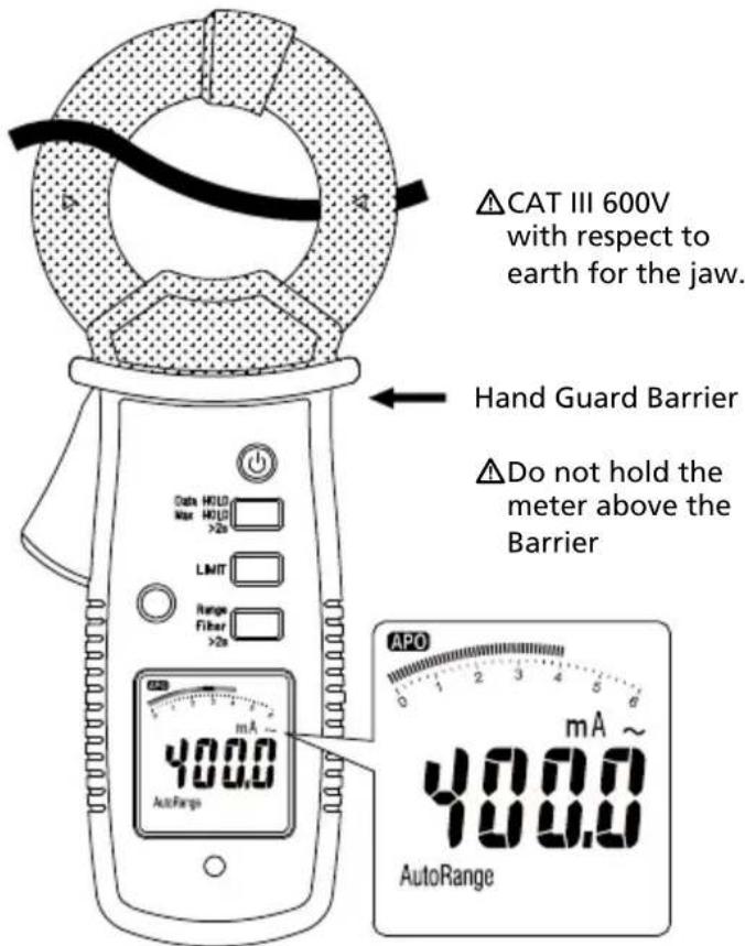
- Do not hold the Product anywhere beyond the tactile barrier.
- When measuring current, center the conductor in the clamp.
- Remove the batteries if the Product is not used for an extended period of time, or if stored in temperatures above 140 °F (60 °C). If the batteries are not removed, battery leakage can damage the Product.
- Replace the batteries when the low battery indicator shows to prevent incorrect measurements.
- Use only 1.5V AAA batteries, properly installed in the Product case, to power the Product.
- Use only 1.5V AAA alkaline batteries and follow all battery care from the manufacturer.
- Never remove the battery cover or open the case of the Product without first removing the jaws from a live conductor.
- The battery door must be closed and locked before you operate the Product.
- Do not leave the Product on or near objects of high temperature.
- For use by competent persons only.
- For safe operation of the Product, do not operate within external low frequency magnetic fields >30 A/m. Ensure the jaw is locked before making measurements.
- Have an approved technician repair the Product.
Caution
- For best accuracy please consider following impacts:
- use whenever possible optimized position of the clamp when the conductor is positioned is in the center of jaw and the angle between conductor and jaw is 90°
- reduce influences by external magnetic field (for impact see error E11 in specification table)
- reduce influences by contamination of the jaw (recommendation for cleaning see in chapter maintenance)
-
The measurement of differential current will be influenced by the load current (for influence of load current, see error E12 in Specification table).
-
If the Product is used in the vicinity of equipment that generates electromagnetic interference, the display may become unstable or the measurements shown may be subject to large errors.
- Do not subject the jaw to unreasonably strong shock, vibration or force.
- If dust gets into the top of the jaw, remove it immediately. Do not close the jaw when dust is trapped in its joints as the sensor may be damaged.
UNPACKING AND INSPECTION
Your package should include:
1 ALC-110 Leakage Current Clamp
2 1.5 V AAA batteries
1 User manual
1 Soft carrying case
If any of the items are damaged or missing, return the complete package to the place of purchase for an exchange.
Note: Batteries do not come installed. Please refer to the Battery Replacement section for further instructions.
FEATURES AND APPLICATIONS
Features
• CAT III 600 V safety rated
- Leakage clamp acc. IEC/EN61557-13, VDE 0413-13
- Low influence of external low frequency magnetic fields @ I_N 3.5 mA ... 600 mA / 40 Hz to 1 kHz: operating class 2, ≤ 30A/m
- True-rms measurements for best accuracy when measuring complex, non-sinusoidal waveforms
- Highest resolution of 0.001 mA, measure up to 60 A:
Range: 6 mA, resolution of 0.001 mA
Range: 60 mA, resolution of 0.01 m
Range: 600 mA, resolution of 0.1 mA
Range: 6 A, resolution of 0.001 A
Range: 60 A, resolution of 0.01 A
- Selectable limits: 3.5 mA, 10 mA, 12 mA, 0.25 mA, 0.5 mA
- Selectable filter function to remove unwanted noise:
- appliance filter (acc. IEC/EN 61557-16),
- 50/60 Hz filter
- no filter
- Frequency range 15 Hz to 1 kHz to cover railway and industrial application
- Max and data hold
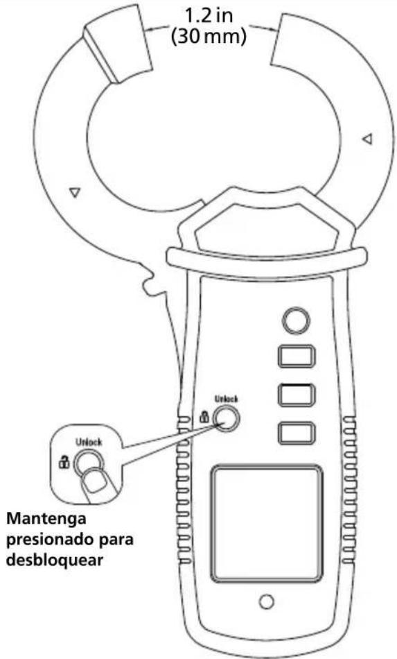
- Mechanical jaw lock
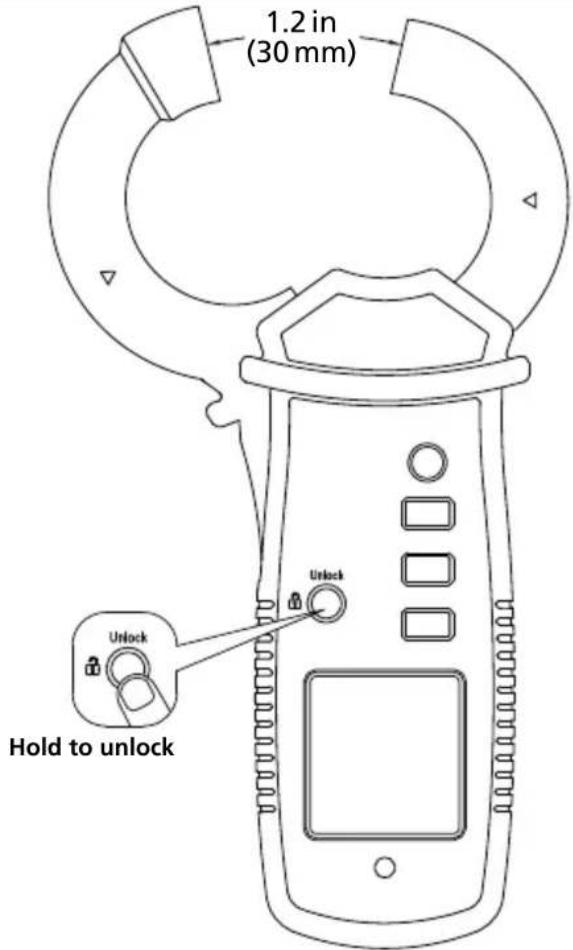
• 1.2 in (30 mm) jaw opening
- Auto backlight
- Auto power off
Applications
• Measurement of earth leakage current.
• Measurement of differential leakage currents.
- Measuring leakage current through the earth (PE) conductor.
- Tracing the source of earth leakage current.
- Measurement of current consumption of appliances in service or customer service sector without interruption to the circuit.
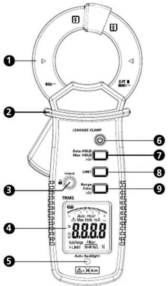
1 Jaw
② Hand barrier
3 Jaw unlock
4 LCD
5 Auto backlight sensor
6 Power
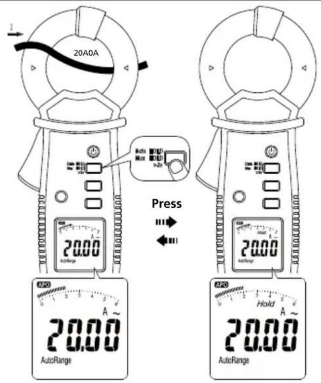
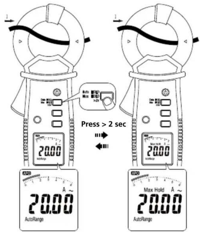
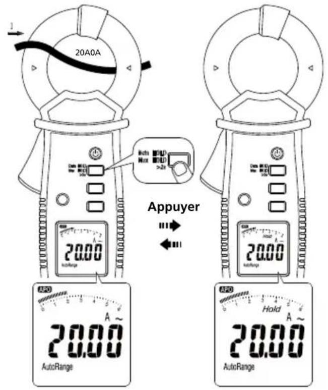
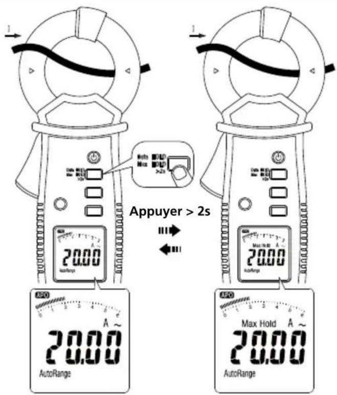
7 Data HOLD
(for Max HOLD press for >2 sec)
8 Limit
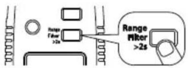
9 Range (for Filter press for >2 sec)
DESCRIPTION OF THE LCD
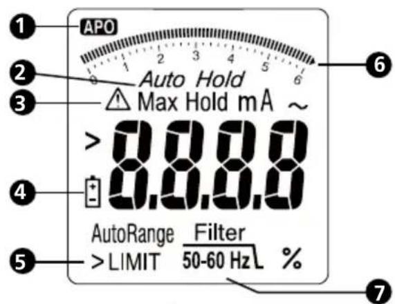
1 Auto power off
② Data/Max hold
3 Warning & caution
4 Low battery
5 Limit function
6 Bar graph
⑦ Appliance filter / 50-60 Hz filter
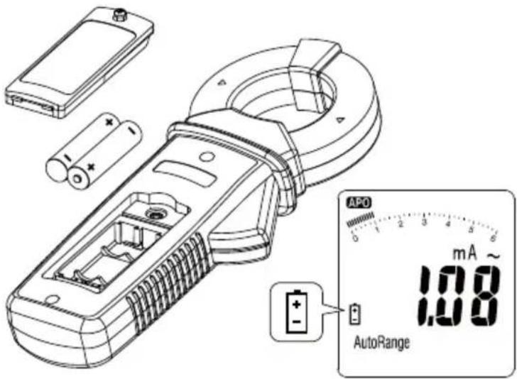
POWER ON/OFF
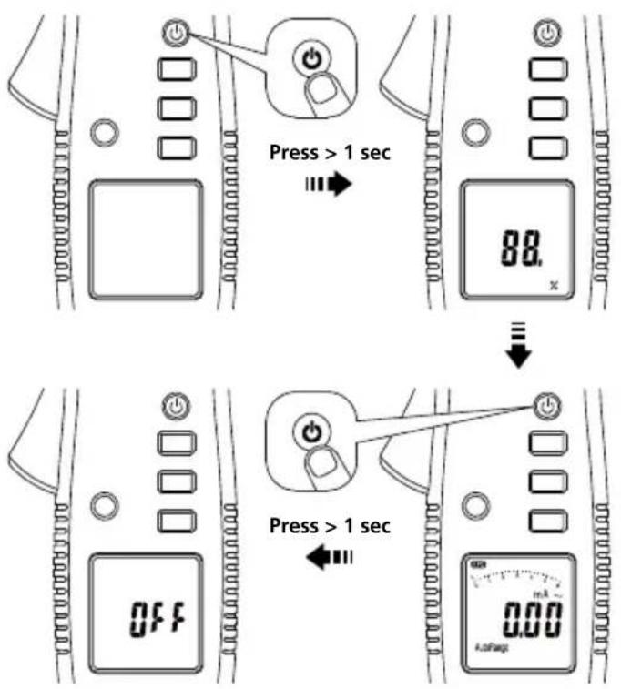
The meter will display battery capacity when powering up. Please replace the battery when less than 10% is shown.
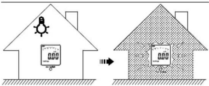
AUTO BACKLIGHT
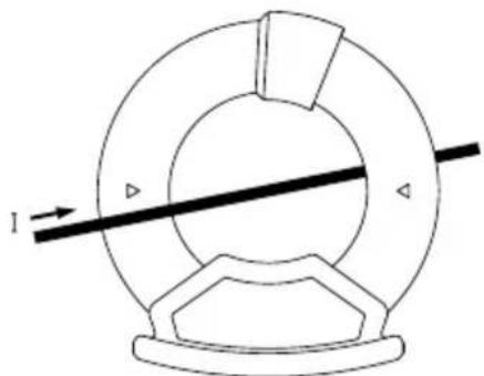
AC CURRENT MEASUREMENT
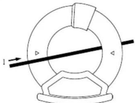
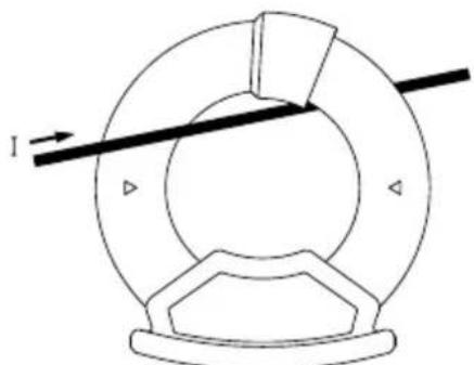
Position Error
natural_image
Pure mechanical diagram of a circular component with a diagonal line and directional arrow, no text or symbols present.OK
natural_image
Pure mechanical diagram showing a circular component with internal blades and a diagonal line, no text or symbols present.
When measuring current, ensure the cable is located in the center of the clamp to avoid position errors.
LEAKAGE CURRENT MEASUREMENT
The leakage current flows when an unintentional electrical connection occurs between an energized part of the electrical system and the earth/ground. The desired value of leakage current should be 0 A. Check applicable regulations and standards for allowable limits of leakage current.
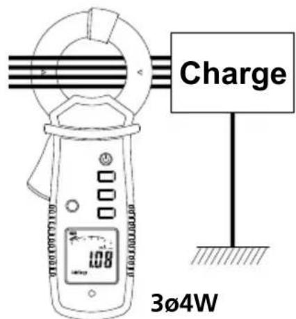
For properly grounded systems, in case of the fault, leakage current should be conducted via earth conductor (PE) (Figure 1). We can measure such current directly in a earth conductor using a leakage clamp meter.
In some cases, specifically when equipment is not properly grounded, the leakage current may flow through other paths. Use differential current measurement methods to verify such current leaks (Figure 2, Figure 3, Figure 4). Clamp a leakage current meter around all active conductors (hot and neutrals), but without any earth conductor. An electromagnetic field around all conductors should cancel each other if there is no current leak and clamp meter should read 0A. If there is a leak, there will be imbalance between electromagnetic fields, and the clamp meter will read the actual value of that leakage current.
Leakage current measurement process
- Turn the meter on.
- Make sure the jaw is closed and the meter is away from conductors and other sources of electromagnetic fields.
- Clamp the meter around a earth conductor. The meter will indicate leakage current in earth conductor.
- Clamp the meter around all active conductors, hot and neutrals (but without earth conductors). The meter will indicate total system leakage current that consists of earth conductor current as well as any other stray current leakage.
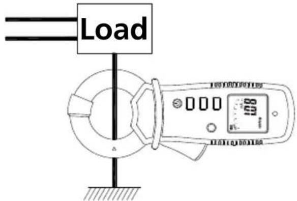
Figure 1: Direct Method Measurement of earth (PE) leakage current
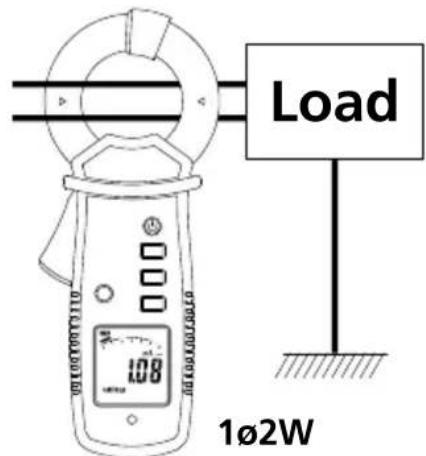
Figure 2
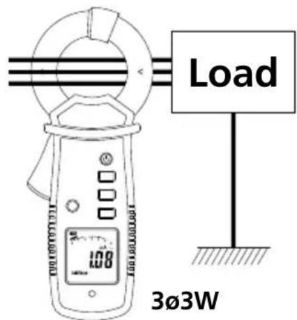
Figure 3
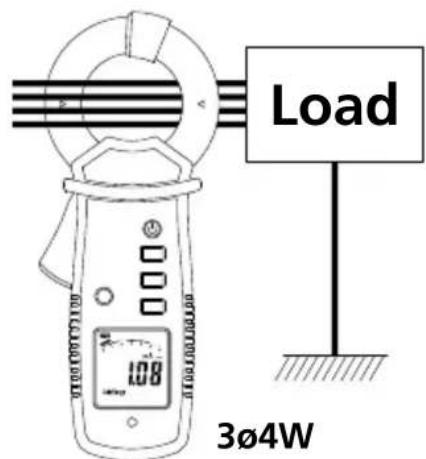
Figure 4
Figure 2, 3 and 4: Differential Method Measurement of differential leakage current
DATA HOLD
MAX HOLD
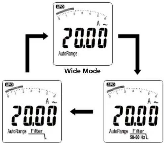
LOW PASS FILTER (50-60 HZ) & APPLIANCE FILTER
Low Pass and Appliance filters are used to filter out high frequency noise that affect precise measurement of the meter.
- Use Low Pass 50/60Hz filter to perform measurements on equipment driven by Variable Frequency Drives (VFDs) or affected by high frequency noise. Significant difference in reading between measurement with and without low pass filter may indicate presence of harmonics.
- Use Appliance Filter to conduct leakage current measurements of appliances in accordance with IEC/EN 61557-16 regulation requirements.
Appliance Filter 50-60 Hz
Auto/ Manual Range
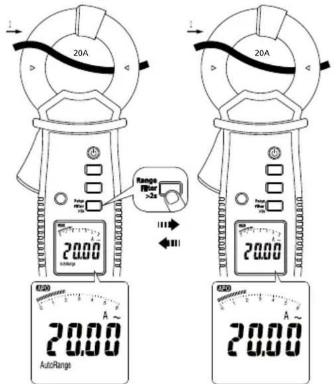
Auto Range Manual Range
LIMIT
Limit selection:
The LIMIT function offers 5 limit values (3.5 mA / 10 mA / 12 mA / 0.25 mA / 0.5 mA) in accordance with safety standards.
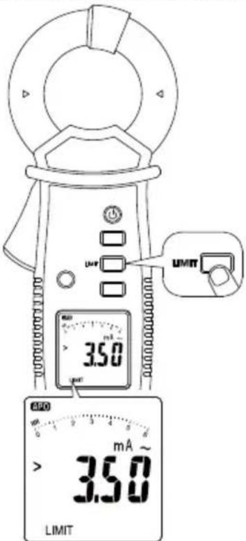
- Continue pressing LIMIT button until desired limit value is selected. The unit will be looping between 3.5 mA / 10 mA / 12 mA / 0.25 mA / 0.5 mA values.
- When desired value is selected wait 2 sec to automatically apply selection. The LIMIT symbol will be displayed on the LCD to indicate that the function is active.
- Verify the selection by pressing the LIMIT button one time. The unit will display the selected value for 2 seconds.
- To disable the LIMIT function, press the LIMIT button for >2 sec.
Display when limit is exceeded:
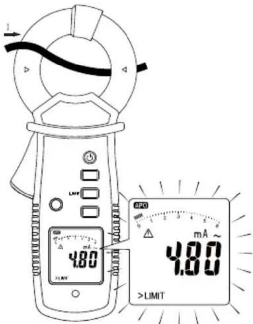
The internal buzzer will continue beeping and the display will flash and show a warning symbol when the measurements exceeds the selected limit value.
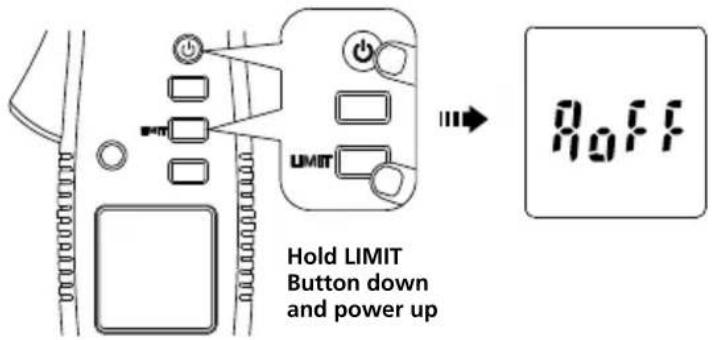
Auto Power Off
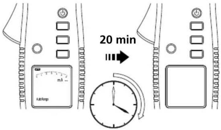
Disable Auto Power Off
SPECIFICATIONS
| Display 6000 counts | digit large scale |
| Sensing True RMS | |
| Update rate 5 per second nominal | |
| Operating temperature and relative humidity | 32 °F to 86 °F (0 °C to 30 °C)(≤ 80% R.H.)86 °F to 104 °F (30 °C to 40 °C)(≤ 75% R.H.)104 °F to 122 °F (40 °C to 50 °C)(≤ 45% R.H.) |
| Storage temperature | -4 °F to 140 °F (-20 °C to 60 °C)(with battery removed) |
| Jaw opening 1.2 in (30 mm) max. | |
| Pollution degree 2 | |
| IP rating IP20 | |
| Operating altitude ≤ | 2000 m |
| Overload protection | 600 V rms |
| Measurement category | CAT III 600 V |
| Safety compliance | IEC 61010-1, IEC 61010-2-032,IEC 61557-13 |
| E.M.C. Meets EN61326-1 | |
| Electromagnetic Compatibility | Korea (KCC): Class A equipment(Industrial Broadcast & Communications Equipment)Class A: Equipment meets requirements for industrial electromagnetic wave equipment and the seller or user should take notice of it. This equipment is intended for use in business environments and not to be used in homes. |
| Current sensor operating class | Class 2, ≤30 A/m acc. IEC/EN 61557-13@ In: 3.500 mA - 600.0 mA / 40 Hz to 1 kHz |
| Selectable limits | 0.250 mA / 0.500 mA / 3.500 mA / 10.00 mA / 12.00 mA |
| Selectable filter functions | Appliance filter(acc. IEC/EN 61557-16),50/60 Hz filter or no filter |
| AC frequency response | 15 Hz ... 1 kHz |
| Operating uncertainty (B) | @ 30 A/m:reading 3.5...10 mA <20%reading >10 mA <12.5%@ 10 A/m:reading 3.5...10 mA <15%reading >10 mA <10%(valid for proper range with best resolution) |
| Intrinsic uncertainty (A) | See ELECTRICAL SPECIFICATIONS |
| Position error (E1) A | Add ±1% of reading |
| Supply voltage error (E2) | N/A |
| Influence of temperature (E3) | Add 0.1 x (Specified accuracy) / °C,< 21 °C, > 25 °C |
| Influence of interference voltages (E4) | N/A |
| Influence of earth electrode resistance (E5) | N/A |
| Influence for phase angle of impedance of circuit under test (E6) | N/A |
| Influence of system frequency (E7) | N/A |
| Influence of system voltage (E8) | N/A |
| Influence of distorted waveform (E9) | N/A |
| Influence of system d.c. quantities (E10) | N/A |
| Influence of external low frequency magnetic fields (E11) | 10 A/m: add ±0.1 mA30 A/m: add ±0.3 mA@ IN: 3.500 mA – 600.0 mA / 40 Hz to 1 kHzand a frequency of the magnetic field of 15 to 400 Hz acc. to IEC 61000-4-8 |
| Influence of load current (E12) | Add ±6 μA per A load current |
| Influence of touch current caused common mode voltage (E13) | N/A |
| Influence of frequency (E14) | N/A |
| Influence of repeatability (E15) | N/A |
| Agency approval | SE US CE IC |
| Power supply Two 1 | 5 V AAA (LR03) batteries |
| Battery life 60 hours | typical |
| Low battery voltage | Approx. 2.5 V |
| Low battery indication | |
| Auto power off Idle | for 20 minutes |
| Dimensions (H x W x L) | 8.7 x 3.5x 1.8 in(221 x 89 x 48 mm) |
| Weight | Approximately 0.90 lb (410 g) with battery installed |
ELECTRICAL SPECIFICATIONS
Accuracy is given as ± (% of reading + counts of least significant digit) at 23 °C ± 2 °C (≤ 80% R.H.)
AC Function
• AC A specifications are AC coupled, true RMS.
- For non-sinusoidal waveforms, Additional Accuracy by Crest Factor (C.F.):
Add 1.0% for C.F. 1.0 to 2.0
Add 2.5% for C.F. 2.0 to 2.5
Add 4.0% for C.F. 2.5 to 3.0
• Max. Crest Factor of Input Signal:
3.0 @ 3000 counts
2.0 @ 4500 counts
1.5 @ 6000 counts
• Frequency Response is specified for sine waveform.
- When operating under magnetic field add error E11.
- When measuring leakage current of multiple conductors, add error E12 for influence of load current.
- For Position Error see error E1.
AC Current
| Range | Accuracy | |||
| 15 to 40 Hz | 40 to 50 Hz | 50 to 60 Hz | 60 to 1 kHz | |
| 6 mA^[1] | ±(5.0%+5D) | ±(2.0%+5D) | ±(1.0%+5D) | ±(2.0%+5D) [2] |
| 60 mA | ±(5.0%+5D) | ±(2.0%+5D) | ±(1.0%+5D) | ±(2.0%+5D) [2] |
| 600 mA | ±(5.0%+5D) | ±(2.0%+5D) | ±(1.0%+5D) | ±(2.0%+5D) [2] |
| 6 A | -±(2.0%+5D) | ±(1.0%+5D) | ±(2.0%+5D) | |
| 60 A | -±(2.0%+5D) | ±(1.0%+5D) | ±(2.0%+5D) | |
[1] Minimum Reading is 0.010 mA
[2] Frequency response is 60 Hz to 10 kHz. When frequency > 1 kHz, add 0.5% to accuracy.
Minimum Resolution: 0.001 mA
Low Pass Filter (50–60 Hz Filter)
| Range | Accuracy |
| 50 to 60 Hz | |
| 6 mA^[1] | ±(1.0%+5D) |
| 60 mA ±(1.0%+5D) | |
| 600 mA ±(1.0%+5D) | |
| 6 A ±(1.0%+5D) | |
| 60 A ±(1.0%+5D) | |
[1] Minimum Reading is 0.010 mA
Minimum Resolution: 0.001 mA
Cut-off frequency: 200 Hz
Appliance Filter (acc. IEC/EN 61557-16)
| Range | Accuracy | |
| 50 to 60 Hz 60 to | 200 Hz | |
| 6 mA^[1] | ±(1.0%+5D)±(2.5%+5D) | |
| 60 mA ±(1.0%+5D)±(2.5%+5D) | ||
| 600 mA ±(1.0%+5D)±(2.5%+5D) | ||
| 6 A | ±(1.0%+5D)±(2.5%+5D) | |
| 60 A | ±(1.0%+5D)±(2.5%+5D) | |
[1] Minimum Reading is 0.010 mA
Minimum Resolution: 0.001 mA
Cut-off frequency: 1 kHz
MAINTENANCE
Do not attempt to repair this meter. It contains no user-serviceable parts. Repair or serving should only be performed by qualified personnel.
-
Inspect the jaw mating surface for cleanliness. If any foreign material is present, the jaw will not close properly and measurement errors will result.
-
Verify that the range on the meter is correct.
Calibration Interval
We suggest a calibration interval of one year. If the instrument is rarely used, the calibration interval can be extended to 3 years.
Cleaning
To avoid damaging the meter, do not use abrasives or solvents to clean it.
Always keep the metal parts of the jaw clean and dry. Avoid allowing dust or other particles to come in-between the jaws. Remove and clean these parts carefully by soft air pressure.
Also ensure that there is no rust or oxidation on the metal surfaces. In case of contamination (dust or oxidation) the commutator segments of the jaw could be damaged or bent. In this case, the current clamp will be damaged and outside specification. Please send the current clamp to service for repair.
BATTERY REPLACEMENT
-
Disconnect the jaw from measuring circuit.
-
Turn the meter OFF.
-
Remove the screws from the battery cover and open the battery cover.
-
Remove the batteries and replace with 2 1.5 V AAA size (IEC R03) batteries. Observe correct polarity when installing the batteries.
-
Replace the battery cover and re-fasten the screw.
ALC-110
FONCTIONS ET APPLICATIONS .... 4
DESCRIPTION DE L'INSTRUMENT .... 5
DESCRIPTION DE L'ÉCRAN LCD....5
MISE SOUS TENSION/HORS TENSION......6
RÉTROÉCLAIRAGE AUTOMATIQUE ...... 6
MESURE DU COURANT CA 7
MESURE DU COURANT DE FUITE 8
CONSERVATION DES DONNÉES......10
CONSERVATION DU MAXIMUM....10
FILTRE PASSE-BAS (50-60 HZ) ET FILTRE POUR
APPAREILS....11
SPÉCIFICATIONS ÉLECTRIQUES ...... 15
MAINTENANCE....17
REMPLACEMENT DES PILES....17
SYMBOLES
FONCTIONS ET APPLICATIONS
Caractéristiques
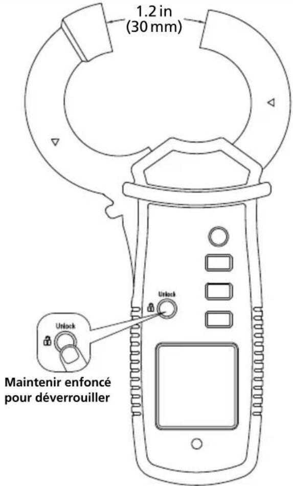
Figure 2
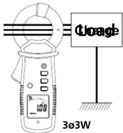
Figure 3
CONSERVATION DES DONNÉES
CONSERVATION DU MAXIMUM
FILTRE PASSE-BAS (50-60 HZ) ET FILTRE POUR APPAREILS
Error de posición
natural_image
Pure mechanical diagram showing a circular component with a central shaft and directional arrow, no text or symbols present.OK

natural_image
Pure mechanical diagram showing a circular component with a central shaft and two protruding components, no text or symbols present.Visit amprobe.com for
- Catalog
- Application notes
• Product specifications - User manuals
Amprobe®
amprobe.com Division of Fluke Corp.
6920 Seaway Blvd.
M/S 143F
Everett, WA 98203 USA
Tel: 877-AMPROBE (267-7623)
Beha-Amprobe®
beha-amprobe.com
c/o Fluke Europe BV
Science Park
Eindhoven 5110
NL-5692 EC Son
Tel.: +49 (0) 7684 8009 - 0

Please Recycle
- Leakage Current Clamp
- User Manual
- Limited Warranty and Limitation of Liability
- Repair
- In-warranty Repairs and Replacement – All Countries
- Non-warranty Repairs and Replacement – United States and Canada
- Non-warranty Repairs and Replacement – Europe
- Beha-Amprobe
- CONTENTS
- SAFETY INFORMATION
- CENELEC Directives
- ⚠ Warning
- Caution
- UNPACKING AND INSPECTION
- FEATURES AND APPLICATIONS
- Features
- Applications
- POWER ON/OFF
- AUTO BACKLIGHT
- AC CURRENT MEASUREMENT
- Position Error
- LEAKAGE CURRENT MEASUREMENT
- Leakage current measurement process
- LOW PASS FILTER (50-60 HZ) & APPLIANCE FILTER
- LIMIT
- Limit selection:
- ELECTRICAL SPECIFICATIONS
- AC Function
- MAINTENANCE
- Calibration Interval
- Cleaning
- BATTERY REPLACEMENT
- ALC-110
- FONCTIONS ET APPLICATIONS
- Caractéristiques
- FILTRE PASSE-BAS (50-60 HZ) ET FILTRE POUR APPAREILS
- Visit amprobe.com for
- Amprobe®
- Beha-Amprobe®
Brand : Amprobe
Model : ALC110
Category : Electric multimeter