
ACDC52NAV - Measuring equipment Amprobe - Free user manual and instructions
Find the device manual for free ACDC52NAV Amprobe in PDF.

| Product Type | True RMS Power Multimeter Clamp |
| Model | ACDC52NAV |
| Brand | Amprobe |
| Power Supply | 9 V alkaline battery (NEDA1604A, IEC6LF22) |
| Battery Life | Approximately 50 hours (without backlight) |
| Display | 10,000 or 4,000 counts with active backlight and analog bar graph |
| Voltage Measurements | AC/DC up to 1,000 V, True RMS, LPF |
| Current Measurements | AC/DC up to 600 A (ACDC52NAV), True RMS, inrush current, peak hold |
| Resistance Measurements | Up to 99.99 kΩ |
| Capacitance Measurements | Up to 3,999 μF |
| Frequency Measurements | 20 Hz to 9.999 kHz |
| Power Measurements | Active power (W) and power factor (PF) in single-phase and three-phase |
| Harmonic Analysis | Total harmonic distortion (THD) up to the 25th order |
| Phase Rotation | Phase sequence indication (1-2-3 or 3-2-1) |
| Special Functions | Non-contact voltage detection (VoltSense), intelligent hold (HOLD), DC A zero, auto/manual range |
| Safety | CAT IV 600 V / CAT III 1,000 V, double insulation |
| Jaw Opening | 45 mm (1.77 in) |
| Drop Resistance | 1.2 m (4 ft) on concrete floor |
| Operating Temperature | 0 °C to 50 °C at RH |
| Storage Temperature | -20 °C to 60 °C, RH 0-80% (without battery) |
| Maintenance | Clean with a damp cloth and mild detergent; remove battery if unused for more than 60 days |
| Repairability | Return to an Amprobe authorized service center for warranty or non-warranty repair |
Frequently Asked Questions - ACDC52NAV Amprobe
User questions about ACDC52NAV Amprobe
0 question about this device. Answer the ones you know or ask your own.
Ask a new question about this device
Download the instructions for your Measuring equipment in PDF format for free! Find your manual ACDC52NAV - Amprobe and take your electronic device back in hand. On this page are published all the documents necessary for the use of your device. ACDC52NAV by Amprobe.
USER MANUAL ACDC52NAV Amprobe
Limited Warranty and Limitation of Liability
Your Amprobe product will be free from defects in material and workmanship for 1 year from the date of purchase. This warranty does not cover fuses, disposable batteries or damage from accident, neglect, misuse, alteration, contamination, or abnormal conditions of operation or handling. Resellers are not authorized to extend any other warranty on Amprobe's behalf. To obtain service during the warranty period, return the product with proof of purchase to an authorized Amprobe Test Tools Service Center or to an Amprobe dealer or distributor. See Repair Section for details. THIS WARRANTY IS YOUR ONLY REMEDY. ALL OTHER WARRANTIES - WHETHER EXPRESS, IMPLIED OR STAUTORY - INCLUDING IMPLIED WARRANTIES OF FITNESS FOR A PARTICULAR PURPOSE OR MERCHANTABILITY, ARE HEREBY DISCLAIMED. MANUFACTURER SHALL NOT BE LIABLE FOR ANY SPECIAL, INDIRECT, INCIDENTAL OR CONSEQUENTIAL DAMAGES OR LOSSES, ARISING FROM ANY CAUSE OR THEORY. Since some states or countries do not allow the exclusion or limitation of an implied warranty or of incidental or consequential damages, this limitation of liability may not apply to you.
Repair
All test tools returned for warranty or non-warranty repair or for calibration should be accompanied by the following: your name, company's name, address, telephone number, and proof of purchase. Additionally, please include a brief description of the problem or the service requested and include the test leads with the meter. Non-warranty repair or replacement charges should be remitted in the form of a check, a money order, credit card with expiration date, or a purchase order made payable to Amprobe® Test Tools.
In-Warranty Repairs and Replacement – All Countries
Please read the warranty statement and check your battery before requesting repair. During the warranty period any defective test tool can be returned to your Amprobe® Test Tools distributor for an exchange for the same or like product. Please check the "Where to Buy" section on www.amprobe.com for a list of distributors near you. Additionally, in the United States and Canada In-Warranty repair and replacement units can also be sent to a Amprobe® Test Tools Service Center (see below for address).
Non-Warranty Repairs and Replacement – US and Canada
Non-warranty repairs in the United States and Canada should be sent to a Amprobe® Test Tools Service Center. Call Amprobe® Test Tools or inquire at your point of purchase for current repair and replacement rates.
In USA In Canada
Amprobe Test Tools Amprobe Test Tools
Everett, WA 98203 Mississauga, ON L4Z 1X9
Tel: 888-993-5853 Tel: 905-890-7600
Fax: 425-446-6390 Fax: 905-890-6866
Non-Warranty Repairs and Replacement – Europe
European non-warranty units can be replaced by your Amprobe® Test Tools distributor for a nominal charge. Please check the "Where to Buy" section on www.amprobe.com for a list of distributors near you.
Amprobe® Test Tools Europe
In den Engematten 14
79286 Glottertal, Germany
tel: +49 (0) 7684 8009 - 0
*(Correspondence only – no repair or replacement available from this address. European customers please contact your distributor.)customers please contact your distributor.)
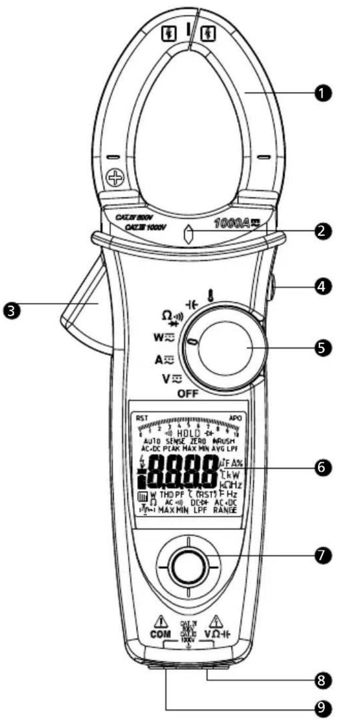
1 Jaw
② Voltsense Light
3 Trigger
4 Hold / DCA Zero Key
5 Rotary Switch
⑥ Display
7 Navigator Key
8 V/Ω/+ Input
9 Common Input
SYMBOLS....1
UNPACKING AND INSPECTION 2
FEATURES....2
OPERATION....3
Making Basic Measurement 4
Measuring Voltage....5
Measuring Current....6
Auto Sense Mode....7
Peak Hold 7
Inrush Current 8
DC A ZERO 9
Measuring Frequency 9
MAX/MIN/AVG....9
THD Measurement....10
LPF 11
Measuring Active Power (W) / Power factor (PF)....12
Phase Rotation 14
OHM Measurements.... 15
Measuring Capacitance 16
Measuring Temperature °C / °F 17
Measuring μA Current.... 18
AUTO / Manual Range 19
HOLD Key 19
VoltSense 20
Buzzer 20
Power-up Option.... 20
Battery State Display.... 20
SPECIFICATION......21
MAINTENANCE AND REPAIR 27
Trouble Shooting.... 27
Cleaning and Storage 27
Battery Replacement 27
SYMBOLS
| Caution ! Risk of electric shock | Caution ! Refer to the explanation in this Manual | ||
| Application around and removal from hazardous live conductors is permitted. | Equipment protected by double or reinforced insulation | ||
| ~ | Alternating Current (AC). | Direct Current (DC). | |
| Temperature Measurement | Resistance Measurement | ||
| Capacitance Measurement | Diode Measurement | ||
| Continuity Beeper | Earth (Ground) | ||
| To alert you to the presence of a potentially hazardous voltage, when the Meter detects a voltage ≥ 30 V or a voltage overload (OL) in V. This symbol is displayed. | Complies with European Directives | ||
| Conform to relevant Australian standards | Battery | ||
| Do not dispose of this product as unsorted municipal waste.Contact a qualified recycler | |||
Safety Information
- Individual protective equipment should be used if HAZARDOUS LIVE parts in the installation where measurement is to be carried out could be ACCESSIBLE
- This manual contains information and warnings that must be followed for operating the instrument safely and maintaining the instrument in a safe operating condition. If the instrument is used in a manner not specified by the manufacturer, the protection provided by the instrument may be impaired.
- The meter is intended only for indoor use.
- The meter protection rating, against the users, is double insulation per IEC/EN 61010-1 3rd Ed, Category III 1000 Volts AC & DC and Category IV 600 Volts AC & DC.
- Disconnect the test leads from the test points before changing the position of the function rotary switch.
- Never connect a source of voltage with the function rotary switch in , +, A , position.
- Do not expose Meter to extremes in temperature or high humidity.
- Never set the meter in , , A, function to measure the voltage of a power supply circuit in equipment that could result in damage the meter and the equipment under test.
Measurement category:
V : Category III 1000 Volts AC & DC, and Category IV 600 Volts AC & DC.
A : Category III 1000 Volts AC & DC, and Category IV 600 Volts AC & DC.
Per IEC 61010-1 3rd Ed. Measurement Category
Measurement Category IV (CAT IV) is for measurements performed at the source of the low-voltage installation. Examples are electricity meters and measurements on primary overcurrent protection devices and ripple control units.
Measurement Category III (CAT III) is for measurements performed in the building installation. Examples are measurements on distribution boards, circuit-breakers, wiring, including cables, bus-bars, junction boxes, switches, socket-outlets in the fixed installation, and equipment for industrial use and some other equipment, for example, stationary motors with permanent connection to the fixed installation.
⚠ WARNING
To reduce the risk of fire or electric shock, do not expose this product to rain or moisture. To avoid electrical shock hazard, observe the proper safety precautions when working with voltages above 60 VDC or 30 VAC rms. These voltage levels pose a potential shock hazard to the user. Do not touch test lead tips or the circuit being tested while power is applied to the circuit being measured. Keep your fingers behind the finger guards of the test leads during measurement. Inspect test leads, connectors,
and probes for damaged insulation or exposed metal before using the instrument. If any defects are found, replace them immediately. Only use the accompanied test leads, or replace with the same rating or better.
UNPACKING AND INSPECTION
Your shipping carton should include:
1 Power clamp meter
1 Test leads (1 pair)
1 Temp. adapter and probe (for ACD-51NAV and ACDC-54NAV only)
1 Users Manual
1 Carrying case
1 9V alkaline battery (installed)
If any of the items are damaged or missing, return the complete package to the place of purchase for an exchange.
FEATURES
- True RMS
- Measurements:
o Voltage up to 1000V AC/DC, Resistance, Frequency, THD (Total Harmonics Distortion) and Individual Harmonics 1 to 25, Power, Power Factor
o AC Current
- Up to 600A (ACD-50NAV, ACD-51NAV, ACDC-52NAV)
- Up to 1000A (ACD-53NAV, ACDC-54NAV)
o DC Current
- Up to 600A (ACDC-52NAV)
- Up to 1000A (ACDC-54NAV)
o Capacitance
o Temperature Measurement in °C / °F (ACD-51NAV, ACDC-54NAV only) - Temp. adapter and probe included
o DC Micro Amps (ACD-51NAV only)
• Phase Rotation Indication
• Non-contact voltage detection
- Inrush Current measurement for motors
- Low Pass Filter for variable frequency drives
- Continuity Beeper
- Min, Max and Smart Data Hold
- Peak Hold
• Auto torch-light when clamping
• Large 10000 count display with active backlight and analog Bar graph
- Auto Power Off
• Maximum Jaw Opening 1.77" (45mm)
- 4 feet Drop Proof
• Deluxe Carrying Case Included
• CAT IV 600V /CAT III 1000V Safety Standard
OPERATION
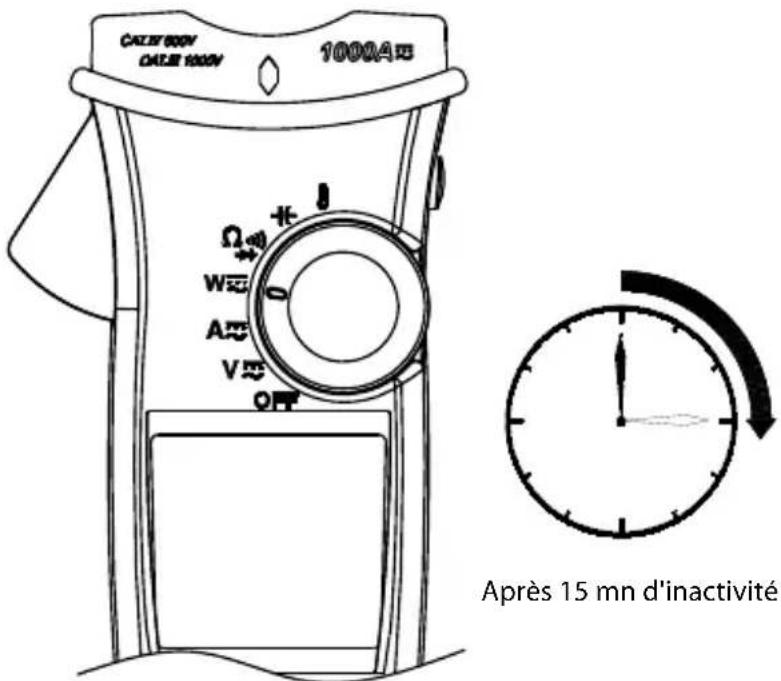
Power On / Off
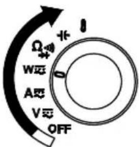
Power on
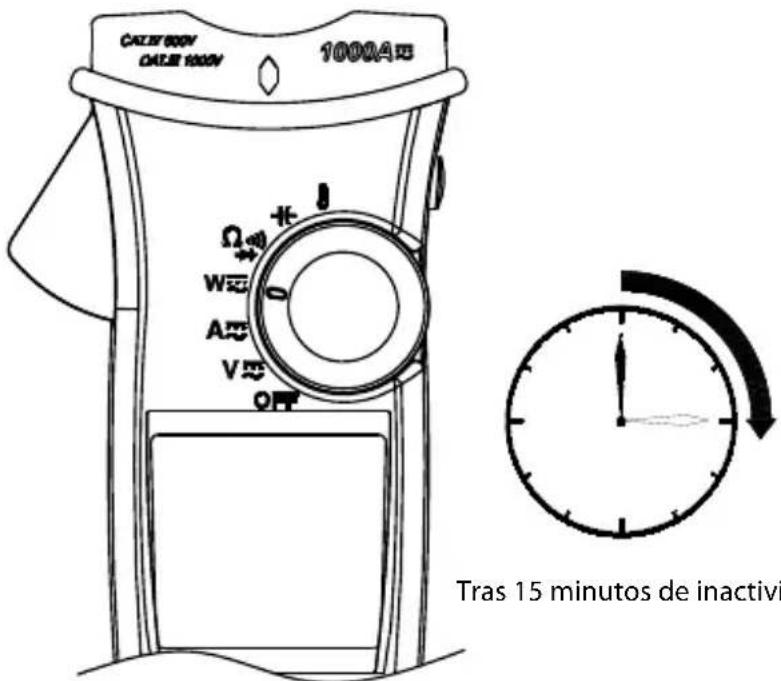
Auto Power Off
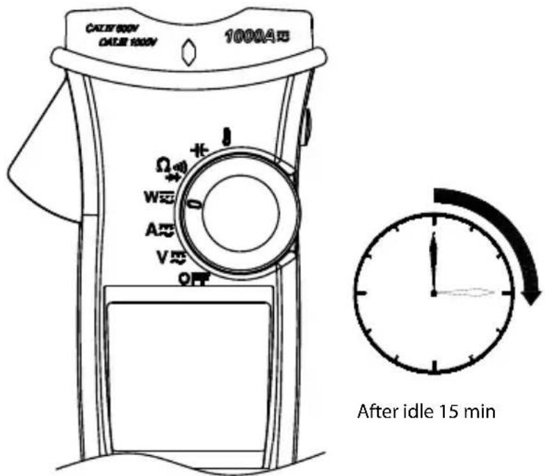
The meter can work again by turning it on from the OFF position.
Auto Power Off (APO) disable : Press "Downward" of Navigator key while tuning meter on from OFF position.
Navigator Key
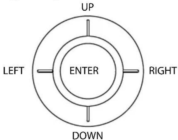
The Navigator Key has 5 directions of switch on the display, toggle the navigator key to select the desired feature to activate the feature by a simple click.
Making Basic Measurements
⚠️ CAUTION
Before and after hazardous voltage measurements, test the voltage function on a known source such as line voltage to determine proper meter functioning.
When connecting the test leads to the EUT (Equipment Under Test) connect the common test lead before connecting the live lead; when removing the test leads, remove the test live lead before removing the common test lead.
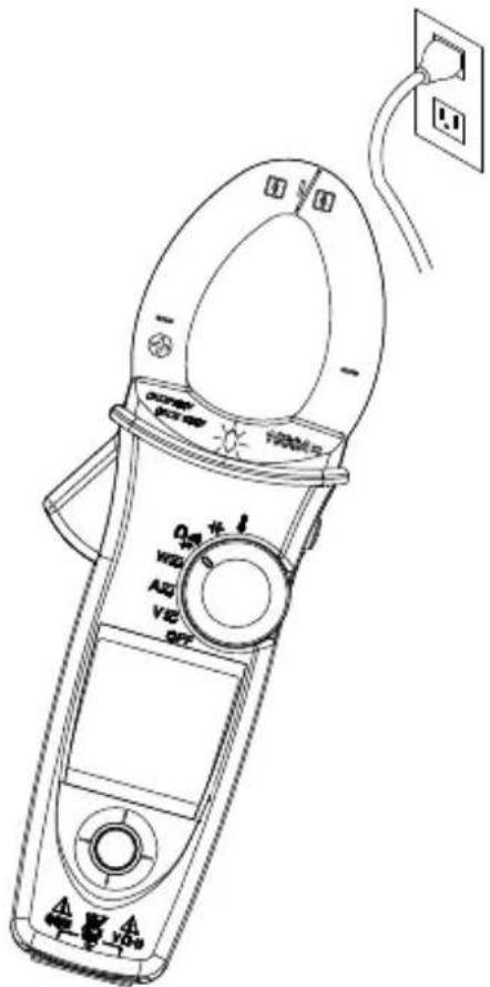
Measuring Voltage
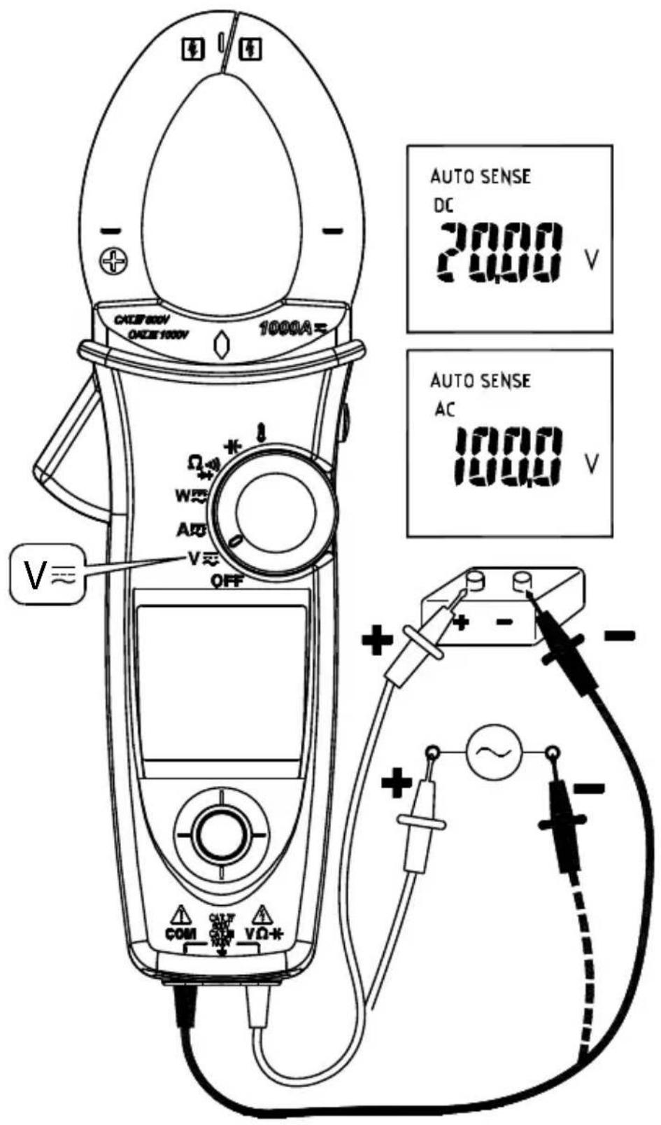
⚠ WARNING
To avoid electrical shock, hazard or damage to meter, do not attempt to measurement that might exceed 1000 V DC or AC RMS. Do not apply more than 1000 V DC or AC RMS to the input terminals.
Note - If the measured voltage is higher than 30 V DC or AC RMS, the display will show "4" symbol.
Measuring Current
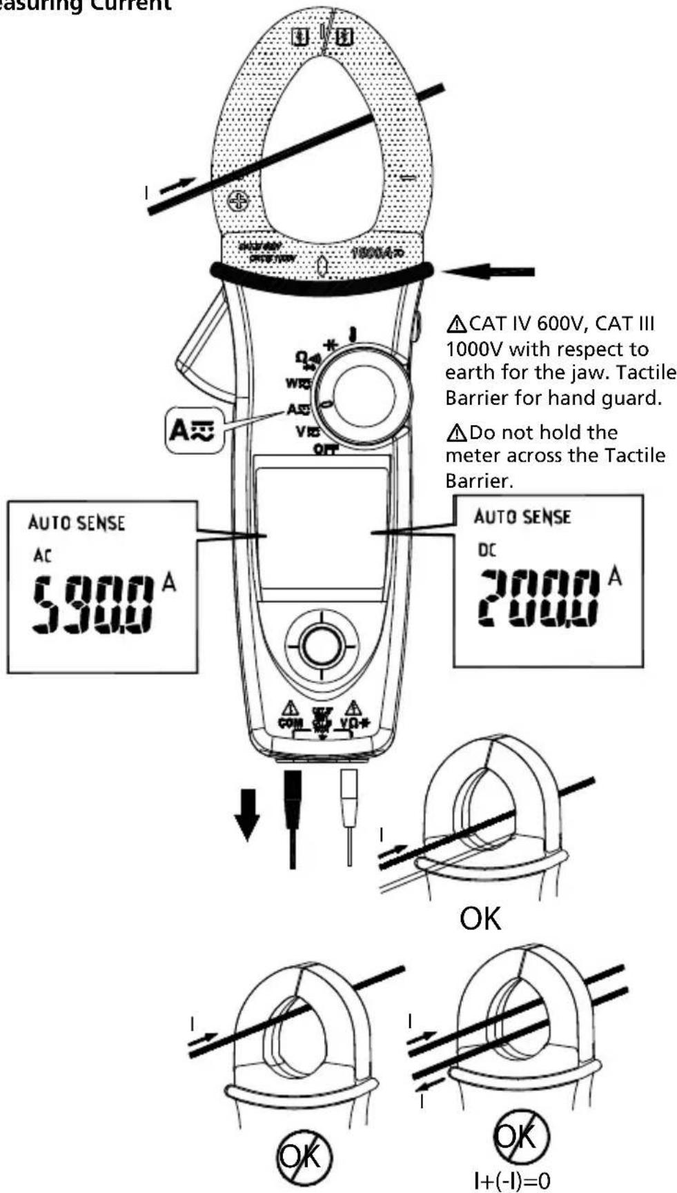
- Don't clamp on any conductor while the meter power on.
- ACD-50NAV, ACD-51NAV or ACD-53NAV has only AC current measurement mode.
- Torch lighting when clamping.
⚠CAUTION
Please do not measure current from clamp jaw when temperature probe is connected to meter.
AUTO SENSE mode:
Display measurement result at AC only with RMS value or DC value, it depends on whichever is greater.
AC mode: AC only with RMS value.
DC mode: DC value.
AC+DC mode: AC+DC RMS value.
Note:
- Select "AC", "DC" or "AC+DC" indicator then press the navigator key to enter the AC/DC/AC+DC mode.
- Select "AC", "DC" or "AC+DC" indicator then press the navigator key for more than 2 seconds to return to the AUTO SENSE mode.
PEAK HOLD (AC mode only)
- In ACV mode, select "Indicator" on the display to enter PEAK HOLD mode. To exit PEAK HOLD mode, press the navigator key for more than 2 seconds.
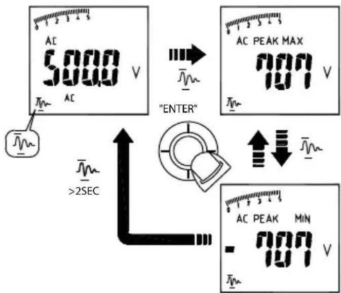
- In AC A mode, select "Indicator" then press the navigator key for more than 2 seconds to enter PEAK HOLD mode. To exit PEAK HOLD mode, just press the navigator key for more than 2 seconds to return to the "Indicator".
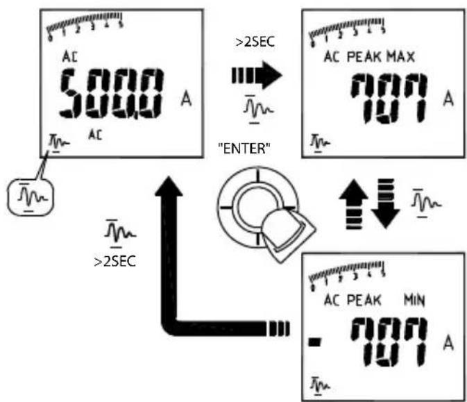
In PEAK HOLD mode, the meter is activated to save the positive peak value and negative peak value. Positive peak value is displayed in PEAK MAX mode. Negative peak value is displayed in PEAK MIN mode.
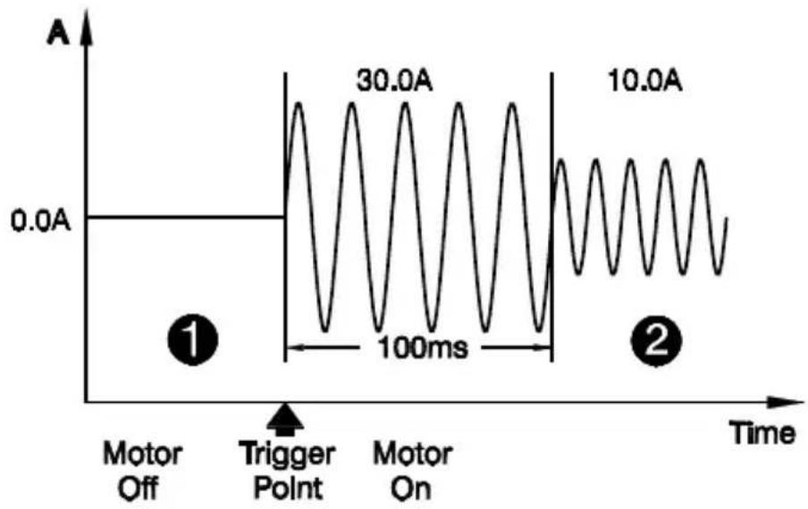
Inrush Current (AC mode only)
If the under testing inrush current could be bigger than 100A ac, please select the range to 600A/1000A in advance before activating inrush current.
In ACA mode, select "1M-1" indicator on the display to enter Inrush Current mode. To exit Inrush Current mode, press the navigator key again.
line
| Time Segment | Amplitude | | ---------------- | --------- | | Trigger Point | 30.0A | | Motor Off | 0.0A | | Motor On | 10.0A |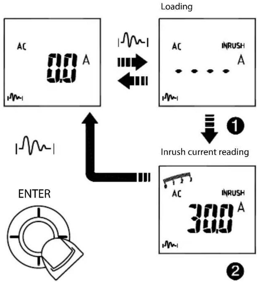
flowchart
graph TD
    A["AC 0.0 A"] --> B["Loading"]
    B --> C["AC INRUSH A"]
    C --> D["INrush current reading"]
    D --> E["AC INRUSH 300 A"]
    E --> F["ENTER"]
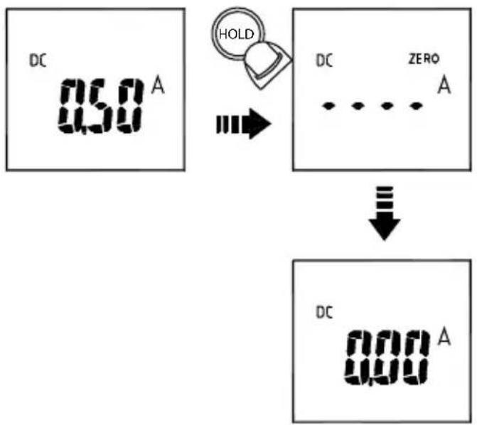
DC A ZERO (For ACDC-52NAV, ACDC-54NAV Only)
Remove the jaw out of the conductor.
Press HOLD Key > 2 seconds to compensate the residual magnetism.
HOLD>2 Sec
flowchart
graph TD
    A["DC 0.58 A"] --> B["HOLD"]
    B --> C["DC ZERO A"]
    C --> D["↓"]
    D --> E["DC 0.00 A"]
- DC A Zero is only available in Auto Sense, DC and AC+DC mode.
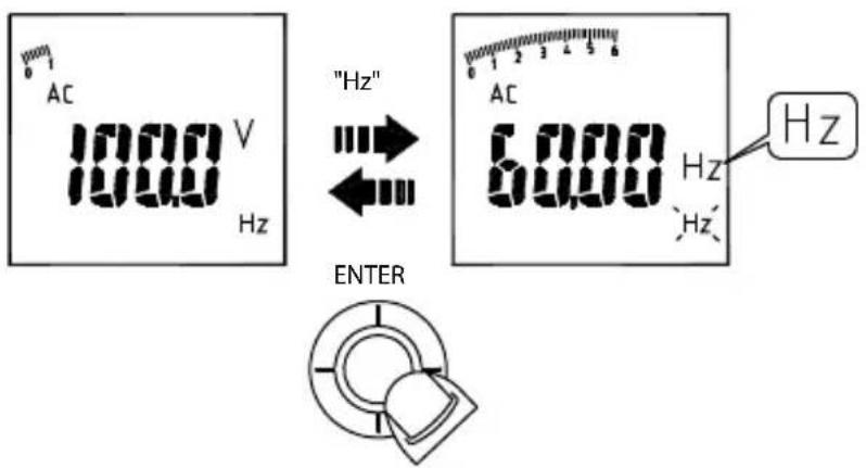
Measuring Frequency (AC mode only)
Select the "Hz" indicator then press the navigator key to enter/exit the frequency measurement mode.
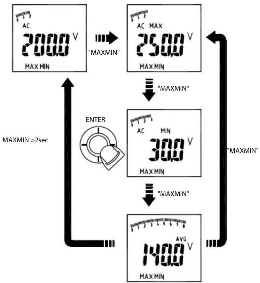
MAX/MIN/AVG
Select the "MAX MIN" indicator then press the navigator key to enter the MAX/MIN/AVG mode. To quit from the MAX/MIN/AVG mode, press the navigator key for more than 2 seconds.
The MAX/MIN/AVG mode records the minimum and maximum input values. When the inputs go below the record minimum value or above the record maximum value, the meter records the new value. The MAX/MIN/AVG mode can also calculate the average of the maximum value and the minimum value.
flowchart
graph TD
    A["AC 2000 V MAX MIN"] -->|MAXMIN"| B["AC MAX 2500 V MAX MIN"]
    B -->|MAXMIN"| C["300 V MAX MIN"]
    C -->|MAXMIN"| D["1400 V MAX MIN"]
    D -->|MAXMIN >2sec| E["ENTER"]
    E --> A
Note :
- Press HOLD key in MAX MIN mode to make the meter stop updating the maximum and minimum value. When the HOLD mode is activated in MAX MIN mode, the HOLD mode must be deactivated before the MAX MIN mode.
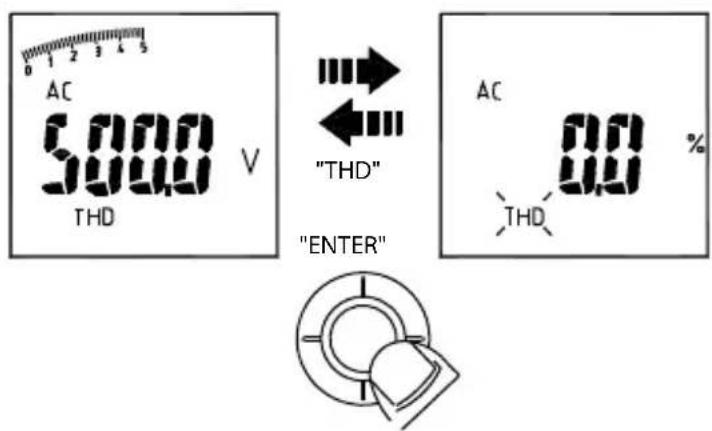
THD Measurement (AC mode only)
Select the "THD" indicator then press the navigator key to enter the THD mode. THD-F=RMS of Harmonics ÷ RMS of fundamental ×100%. (harmonics up to the 25th)
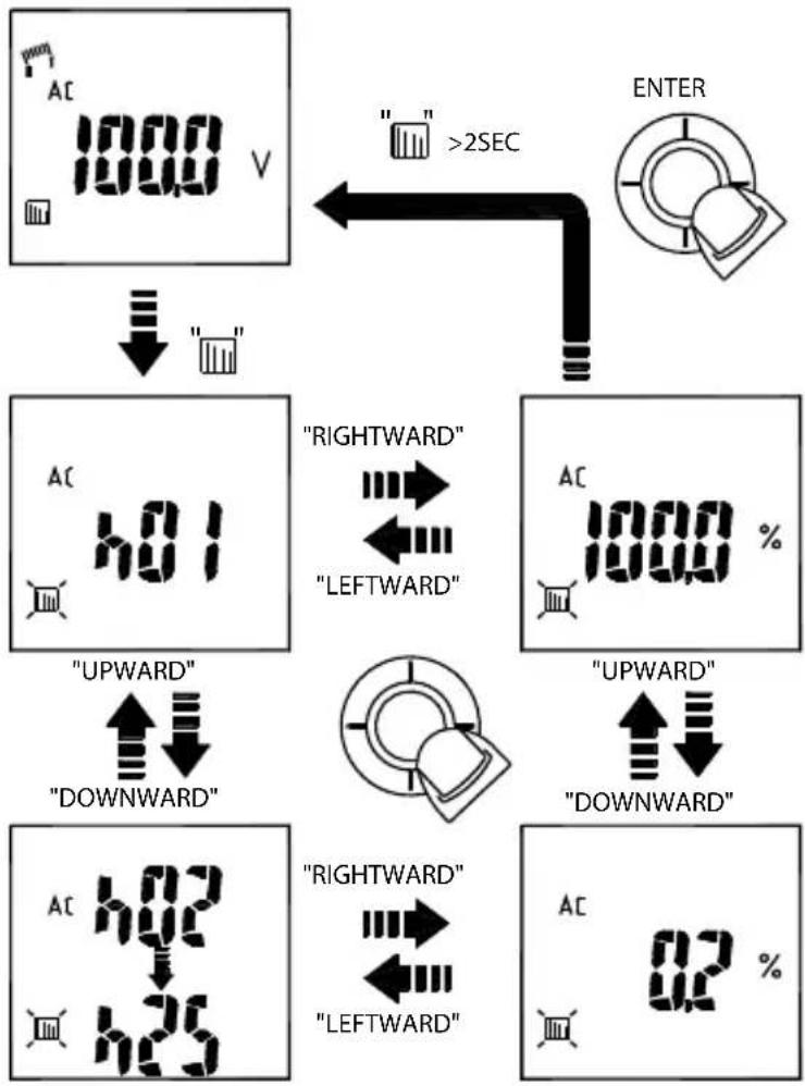
Individual Harmonic Measurement (AC mode only)
Select the "indicator then press the navigator key to enter the individual harmonic mode. To quit from the individual harmonic mode, press the navigator key for more than 2 seconds.
Hn=RMS of Individual Harmonic ÷ RMS of fundamental ×100%.
flowchart
graph TD
A["AC 1000 V"] --> B[""] --> C[""] --> D["ENTER"]
D --> E["RIGHTWARD" <--> "LEFTWARD"]
E --> F["UPWARD" <--> "DOWNWARD"]
F --> G["RIGHTWARD" <--> "LEFTWARD"]
G --> H["UPWARD" <--> "DOWNWARD"]
H --> I["RIGHTWARD" <--> "LEFTWARD"]
I --> J["42 %"]
LPF (AC mode only)
Select the "LPF" indicator then press the navigator key to eliminate high frequency noise
Note : Peak Hold, Inrush, THD, HZ, individual Harmonic and LPF mode are only available in AC mode.
Measuring Active Power (W) / Power factor (PF)
1. Single Phase Power Measurement
Step1. Set the rotary switch to the "W" position.
Step2. Connect the Red test lead to the Line conductor, and the Black test lead to the Neutral conductor.
Step3. Press the trigger to open the transformer jaws and clamp one conductor only, make sure that the jaw is firmly closed around the conductor.
Step4. Using the Navigator key to choose the "W/PF" mode.
Note :
- The “ + ” symbol on the jaw must face on the power source side.
- In AutoSense mode, the meter will displays ACW/DCW depends on if there is AC frequency detected.
- ACD-50NAV, ACD-51NAV and ACD-53NAV offer AC power measurement mode only.
Active power sign :
No sign : Indicates the power flows from the power source to the load.
“_” sign : Indicates the power flows from the load to the power source.
Power factor sign :
No sign : The phase of the current signal is lagging behind the voltage signal (inductive load).
“_” sign : The phase of the current signal is leading the voltage signal (capacitive load).
Overrange display :
OL.U : Voltage overload
OL.A : Current overload
OL.UA : Both Voltage and current overload.
± OL kW : Active Power > 1000 kW or < -1000 kW.
2. Three Phase Power Measurement
A. 3 phase 3 wire balanced / unbalanced
Step 1. Set the rotary switch to the "W" position
Step 2. Using the Navigator key to choose the "W" mode.

B. 3 phase 4 wire balanced / unbalanced
Step1. Set the rotary switch to the "W" position
Step2. Using the Navigator key to choose the "W" mode.
Phase Rotation
Note :
- Connect three phase of power source as shown above.
- The test is only available while the system frequency is stable.
Step 1. Set the rotary switch to the "W" position.
Step 2. Using the Navigator key to choose the "FIRST" mode
Step 3. Connect the Red test lead and Black test lead to any of the line conductor (e.g. Red test lead to the phase Line 1, and Black test lead phase Line 3).
Note: If the followings occur, the meter will not be able to determine the line phase:
The screen displays "OLU" and blinking: voltage > 1000V
The screen displays "LoU" and blinking: voltage < 30V
The screen displays "outF" and blinking: frequency > 65Hz or < 45Hz
Step 4. When the BUZZER beeps twice, change one of the test lead to another line conductor within 3 seconds
The screen will display the result as below:
a) If it displays "123", then the phase sequence is forward sequence
b) If it displays "321", then the phase sequence is reversed sequence
c) When displayed “----” means it is unable to determine line phases.
d) If it displays "LoU", it is possible that you remove the test leads before the meter completing its testing procedures.
Step 5. To repeat the test, using the Navigator key and choose the "(RST)" mode again.
OHM Measurement
⚠ CAUTION
To avoid possible damage to the Meter or to the equipment under test, disconnect circuit power and discharge all high-voltage capacitors before measuring resistance and diode.
Note:
- Select / / indicator then press the navigator key to enter the / / mode.
- Select / mm / → indicator then press the navigator key for more than 2sec to return to the AUTO SENSE mode.
Note: Under diode mode: when the screen displays "bad" when measuring a diode, the diode may have been damaged.
Measuring Capacitance
Set the rotary switch to the “-” position.
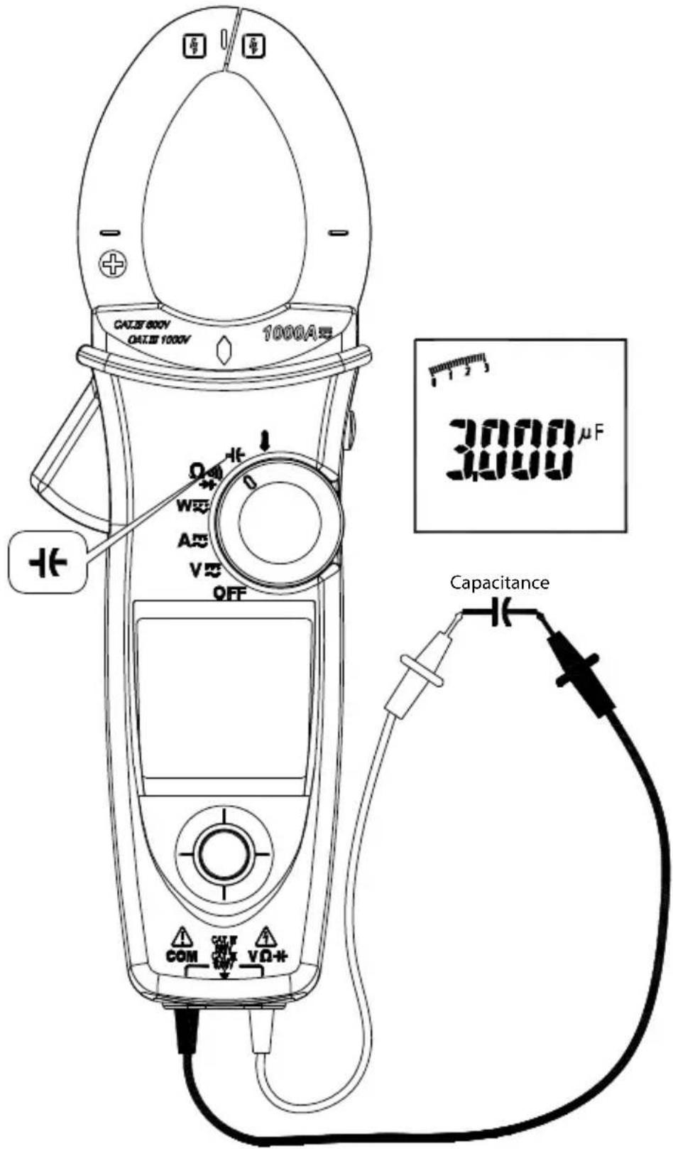
⚠️ CAUTION
To avoid possible damage to the meter or to the equipment under test, disconnect circuit power and discharge all high-voltage capacitors before measuring capacitance. Use the DC voltage function to confirm that the capacitor is discharged.
Note: The meter will display "diSC" while discharging the capacitor.
Measuring Temperature °C / °F (For ACD-51NAV and ACDC-54NAV Only)
Set the rotary switch to the "A" position.
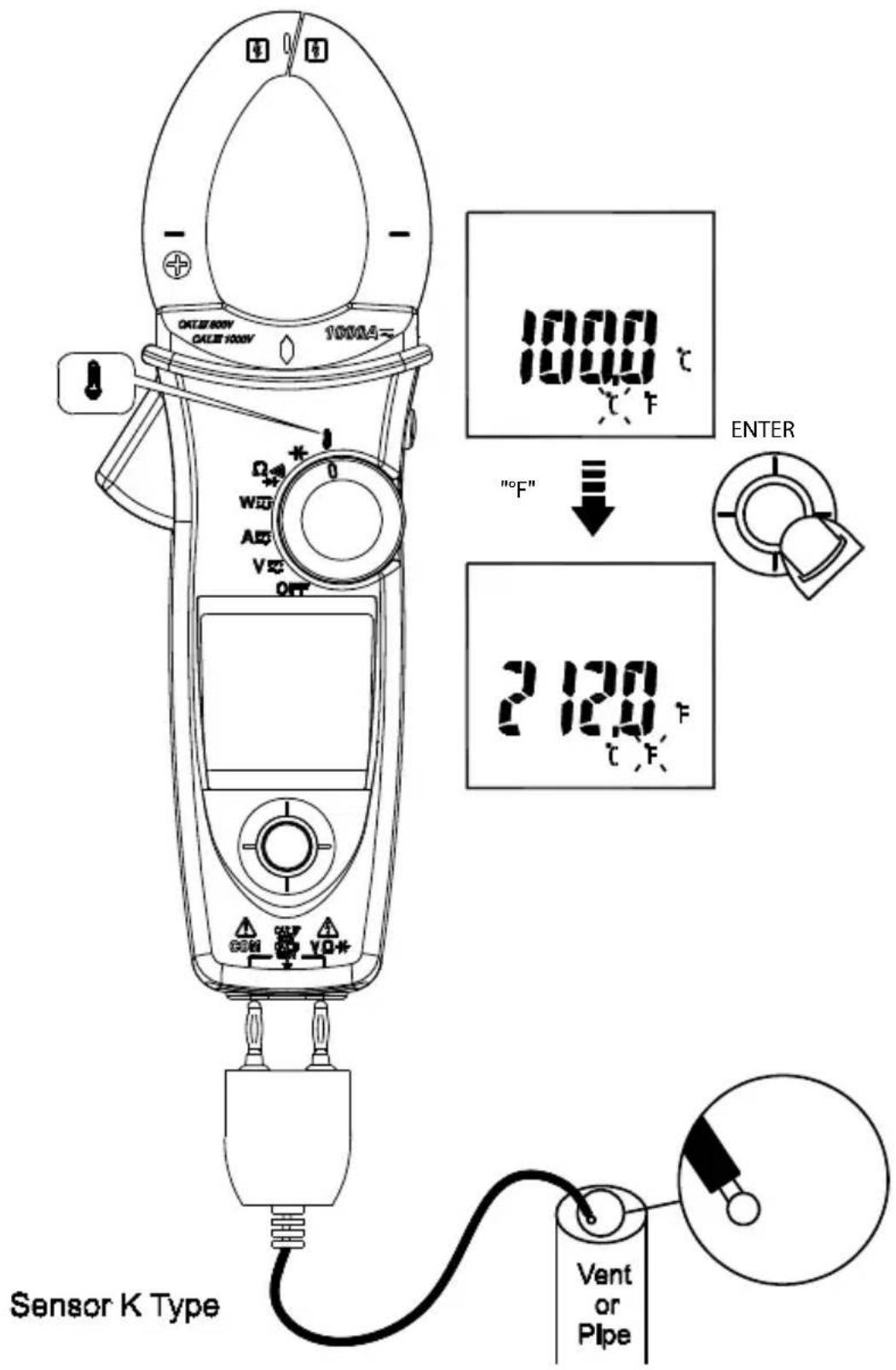
Don't take any high voltage measurement prior to accurate ^ / ^ measurements.
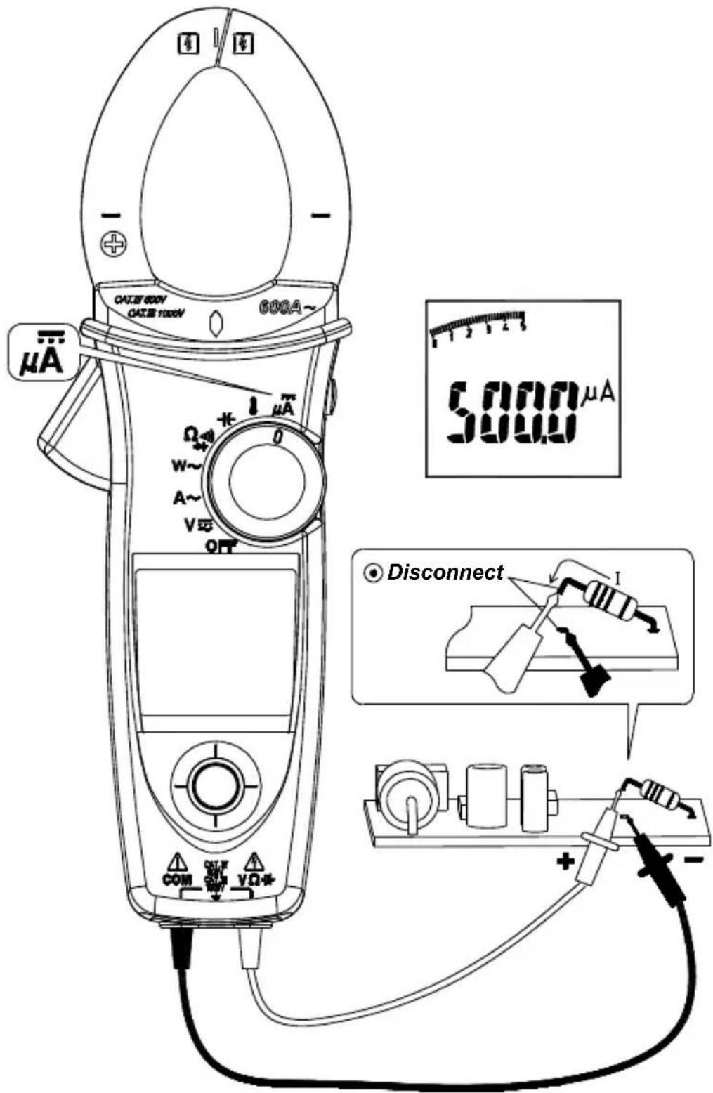
Measuring μA Current (For ACD-51NAV Only)
Set the rotary switch to the A position.
Other Function :
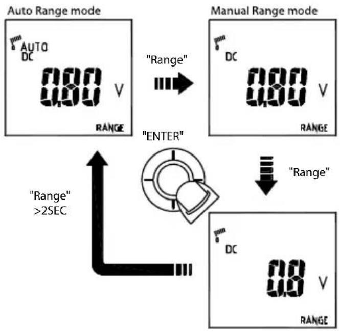
AUTO/MANUAL Range
Select the "RANGE" indicator, then press the navigator key to enter the manual range mode. To return to the auto range mode, press the navigator key for more than 2 seconds.
HOLD Key
Press HOLD key to freeze display value.
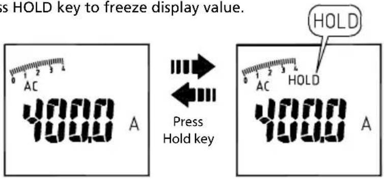
SMART HOLD: The meter will beep continuously and the display will flash if the measured signal is larger than the display reading. (for V.A.W function)
VoltSense
The red diamond shape of LED will illuminate, if there has electric field been detected from the jaw.
Buzzer
The Meter beeps once for every valid key-press, and beeps twice for every invalid key-press.
Power-up options
Press one of the following keys while turning meter on from OFF position.
Upward of Navigator key: Display of the software version.
Downward of Navigator key: Disable auto power off.
Leftward of Navigator key: Disable active backlight.
HOLD KEY: Display all LCD symbols approx 10 seconds.
Battery State display
User can know the battery state from the battery indicator
| Batter State Description | |
| [8202] | The battery is fully charged |
| [3K71] | The battery is remained 2/3 power |
| [16N43] | The battery is remained 1/3 power |
| [44KW] | Replace the battery as soon as the low battery indicator appears, to avoid inaccurate reading. |
Refer to MAINTENANCE AND REPAIR section for battery replacement.
SPECIFICATIONS
General Specifications
Display count : 10000 or 4000
Measuring rate : 3 times / per second
Overrange display: "OL" or "-OL".
Auto Power Off : Approx. 15 minutes.
Low battery indicator : ☐ is displayed. Replace the battery when the indicator appears in the display.
Power requirement : 9V battery.
Battery life : ALKALINE 9V 50 hours (without Backlight).
Environmental Conditions
Indoor Use
Calibration: One year calibration cycle.
Operating temperature: 0 °C \~ 10 °C
11 °C \~ 30 °C (≤80% RH)
30^ 40^ (≤75% RH)
40 °C \~ 50 °C (≤45%RH)
Storage temperature: -10 to 50 °C for current,
-20 to 60 °C for other function,
0 to 80% RH (batteries not fitted).
Temperature coefficient: 0.2 x (Specified accuracy) / °C, < 18°C, > 28°C.
Over voltage category: CAT IV 600 V, CAT III 1000 V : IEC61010-2-030 and 61010-2-032
| CAT Application field |
| IThe circuits not connected to mains. |
| IIThe circuits directly connected to Low-voltage installation. |
| IIIThe building installation. |
| IVThe source of the Low-voltage installation. |
CENELEC Directives: The instrument conforms to CENELEC Low-voltage directive 2006/95/EC and Electromagnetic compatibility directive 2004/108/EC.
Safety Compliance:
- IEC/EN 61010-1 Ed. 3.0, UL 61010-1(2nd Ed.), CAN/CSA-C22.2 No.61010-1-04 to Measurement Category III 600 V, Pollution Degree 2
- IEC/EN 61010-2-030
- IEC/EN 61010-2-032, CAN/CSA-C22.2 No.61010-2-032-04
- IEC/EN 61010-031 (test leads)
EMC: meets all applicable requirements in IEC/EN 61326-1
Operating altitude: up to 2000m (6562 ft)
Conductor Size:
37mm diameter for ACD-50NAV, ACD-51NAV, ACDC-52NAV
42mm diameter for ACD-53NAV, ACDC-54NAV
Shock vibration: Sinusoidal vibration per MIL-T-28800E (5 \~ 55 Hz, 3g maximum).
Drop Protection: 4 feet drop to hardwood on concrete floor.
Electrical Specifications
Accuracy is ±(% reading + number of digits) at 23^ C ± 5^ C < 80% RH.
(1) Voltage
| ACD-50NAV, ACD-51NAV, ACDC-52NAV, ACD-53NAV, ACDC-54NAV | ||
| Function Range Accuracy* | ||
| DC V | 99.99V | ± (0.7% + 2dgt) |
| 999.9V | ||
| AC V | 99.99V | ± (1.0% + 5dgt) |
| 999.9V | 50 ~ 500Hz | |
| LPF | 99.99V | 50 ~ 60Hz ± (1% + 5dgt) |
| 999.9V | 61 ~ 400Hz ± (5% + 5dgt) | |
* DCV <1000dgt, add 6 dgt to the accuracy. ACV <1000dgt, add 3 dgt to the accuracy.
Overload protection: 1000Vrms
Input Impedance: 3.5MΩ // <100pF
AC Conversion Type: AC Conversions are ac-coupled, true RMS responding, calibrated to the RMS value of a sine wave input. Accuracies are given for sine wave at full scale and nonsine wave below half scale. For non-sine wave (50/60Hz) add the following Crest Factor corrections:
For Crest Factor of 1.4 to 2.0, add 1.0% to accuracy.
For Crest Factor of 2.0 to 2.5, add 2.5% to accuracy.
For Crest Factor of 2.5 to 3.0, add 4.0% to accuracy.
CF 3 @ 460V,460A (for ACD-53NAV, ACDC-54NAV),
280A (for ACD-50NAV, ACD-51NAV, ACDC-52NAV)
2 @ 690V, 690A (for ACD-53NAV, ACDC-54NAV),
420A (for ACD-50NAV, ACD-51NAV, ACDC-52NAV)
AC+DC Vrms Accuracy: same as ACV spec. +DCV spec.
(2) Current
| ACD-50NAV, ACD-51NAV, ACD-53NAV | ||
| Function Range Accuracy | ||
| AC A | 99.99A | 50 ~ 60Hz ± (1.5% + 5dgt) ** |
| 599.9A / 999.9A* | 61 ~ 400Hz ± (2% + 5dgt) ** | |
| LPF | 0.10A ~ 99.99A | 50 ~ 60Hz ± (1.5% + 5dgt) ** |
| AC A | 599.9A / 999.9A* | 61 ~ 400Hz ± (5% + 5dgt) ** |
* ACD-50NAV, ACD-51NAV: 599.9A; ACD-53NAV : 999.9A
** The measured value <1000dgt, add 5 dgt to the accuracy.
| ACDC-52NAV, ACDC-54NAV | ||
| Function Range Accuracy | ||
| DC A | 99.99A ± (1.5% + 0.2A) | |
| 599.9A / 999.9A* ± | (1.5% + 5dgt) ** | |
| AC A | 0.10A ~ 99.99A | 50 ~ 60Hz ± (1.5% + 5dgt) ** |
| 599.9A / 999.9A* | 61 ~ 400Hz ± (2% + 5dgt) ** | |
| LPF | 0.10A ~ 99.99A | 50 ~ 60Hz ± (1.5% + 5dgt) ** |
| AC A | 599.9A / 999.9A* | 61 ~ 400Hz ± (5% + 5dgt) ** |
* ACDC-52NAV: 599.9A ; ACDC-54NAV: 999.9A
** The measured value <1000dgt, add 5 dgt to the accuracy.
Overload protection: 1000Arms For ACD-53NAV, ACDC-54NAV
600Arms For ACD-50NAV, ACD-51NAV, ACDC-52NAV
Position Error: ±1% of reading.
AC Conversion Type and additional accuracy is same as AC Voltage.
AC+DC Arms Accuracy: Same as ACA spec + DCA spec.
- For better measurement accuracy of high current, do not measurement more than 10 minutes (for ACD-50NAV, ACD-51NAV, ACD-53NAV)
- DC A affected by the temperature and the residual magnetism.
Press HOLD key > 2 seconds to compensate it.
(3) Peak Hold : Peak MAX / Peak MIN
| ACD-50NAV, ACD-51NAV, ACDC-52NAVV | ||
| Function Range Accuracy | ||
| AC V | 140.0V | ± (3.0% + 15dgt) |
| 1400V | ||
| AC A | 140.0A | ± (3.0% + 15dgt) |
| 850A | ||
| ACD-53NAV, ACDC-54NAV | ||
| Function Range Accuracy | ||
| AC V | 140.0V | ± (3.0% + 15dgt) |
| 1400V | ||
| AC A | 140.0A | ± (3.0% + 15dgt) |
| 1400A | ||
Overload protection: 1000 Vrms
600 Arms For ACD-50NAV, ACD-51NAV, ACDC-52NVA
1000 Arms For ACD-53NAV, ACDC-54NAC
Accuracy defined for:
Sine wave, ACV>5Vrms / ACA≥5Arms, Freq. 50\~400Hz.
- Only suitable for the repetitive events.
(4) Frequency
| ACD-50NAV, ACD-51NAV, ACDC-52NAV, ACD-53NAV, ACDC-54NAV | ||
| Function Range Accuracy | ||
| Frequency | 20.00 ~ 99.99Hz | ± (0.5% + 3dgt)20.0 ~ 999.9Hz |
| 0.020 ~ 9.999KHz | ||
Overload protection : 1000 Vrms
600 Arms For ACD-50NAV, ACD-51NAV, ACDC-52NAV
1000 Arms For ACD-53NAV, ACDC-54NAV
Sensitivity :
10\~100Vrms for AC 100V range
10\~100Arms for AC 100A range (>400Hz Unspecified)
100\~1000Vrms for AC 1000V range
100\~600/1000Arms for AC 600A/1000A range (>400Hz Unspecified)
- Reading will be 0.0 for signals below 10.0 Hz.
(5) Total Harmonic Distortion:
| ACD-50NAV, ACD-51NAV, ACDC-52NAV, ACD-53NAV, ACDC-54NAV | ||
| Function Range Accuracy | ||
| AC A / AC V 99 | 9% ± (3.0% + 10dgt) | |
Harmonic distortion measurement:
| ACD-50NAV, ACD-51NAV, ACDC-52NAV, ACD-53NAV, ACDC-54NAV | ||
| Harmonic order | Range Accuracy | |
| H01 ~ H12 | 99.9%10% + 10dgt) | ± (5% + 10dgt) |
| H13 ~ H25 ± (10% + 10dgt) | ||
Overload protection: 1000 Vrms
600 Arms For ACD-50NAV, ACD-51NAV, ACDC-52NAV
1000 Arms For ACD-53NAV, ACDC-54NAV
- If ACV<10Vrms or ACA <10Arms, it will display "rdy".
- If the fundamental frequency out of range 45 \~ 65Hz, it will display "out.F".
(6) Inrush Current:
| ACD-50NAV, ACD-51NAV, ACDC-52NAV, ACD-53NAV, ACDC-54NAV | ||
| Function Range Accuracy | ||
| AC A | 99.99A ± (2.5% + 0.2A) | |
| 599.9A / 999.9A * ± (2.5% + 5dgt) | ||
* ACD-50NAV, ACD-51NAV, ACDC-52NAV: 599.9A
ACD-53NAV, ACDC-54NAV : 999.9A
Overload protection: 1000 Vrms
600 Arms For ACD-50NAV, ACD-51NAV, ACDC-52NAV
1000 Arms For ACD-53NAV, ACDC-54NAV
Accuracy defined for:
Sine wave, ACA≥10Arms, Freq. 50/60Hz
- Integration time about 100m seconds
(7) Active Power : Watt (DC/AC)
| ACD-50NAV, ACD-51NAV, ACDC-52NAV, ACD-53NAV, ACDC-54NAV | ||
| Function Range Accuracy | ||
| AC W / DC W | 9.999KW** | A,error×V,reading+V,error×A,reading |
| 99.99KW | ||
| 599.9KW / 999.9KW* | ||
* ACD-50NAV, ACD-51NAV, ACDC-52NAV: 599.9KW
ACD-53NAV, ACDC-54NAV: 999.9KW
** The measured value<1.000kW, add 10 dgt to the accuracy.
Overload protection : 1000 Vrms
600 Arms For ACD-50NAV, ACD-51NAV, ACDC-52NAV
1000 Arms For ACD-53NAV, ACDC-54NAV
Accuracy defined for :
AC W :
Sine wave, ACV≥ 10 Vrms, ACA≥ 5 Arms
Freq. 50\~60Hz, PF=1.00
DCW (For ACDC-52NAV, ACDC-54NAV only):
DCV ≧ 10V, DCA ≧ 5 A
(8) Power Factor:
| ACD-50NAV, ACD-51NAV, ACDC-52NAV, ACD-53NAV, ACDC-54NAV | ||
| Function Range Accuracy* | ||
| PF -1.00 ~ | 0.00 ~1.00 ±3°±1dgt | |
* ACA<100A, add ±2° to the accuracy (For ACD-50NAV, ACD-51NAV, ACD-53NAV)
Overload protection : 1000 Vrms
600 Arms For ACD-50NAV, ACD-51NAV, ACDC-52NAV
1000 Arms For ACD-53NAV, ACDC-54NAV
(9) Resistance & Continuity & Diode:
| ACD-50NAV, ACD-51NAV, ACDC-52NAV, ACD-53NAV, ACDC-54NAV | ||
| Function Range Accuracy | ||
| Resistance | 999.9 Ω ± (1.0% + 5dgt) | |
| 9.999 kΩ | ± (1.0% + 3dgt) | |
| 99.99 kΩ | ||
| Continuity | 999.9 Ω ± (1.0% + 5dgt) | |
| Diode 0.4 | 0 ~ 0.80V ± 0.1V | |
Overload protection : 1000Vrms
Max. Test Current : Approx. 0.5mA.
Maximum Open Circuit Voltage for , [11]) Approx. 3V
Maximum Open Circuit Voltage for diode : Approx. ±1.8V
Continuity check :
Continuity Threshold: <30 ohm Beep On.
<100 ohm Beep Off.
Continuity Indicator : 2 KHz Tone Buzzer
(10) Capacitance:
| ACD-50NAV, ACD-51NAV, ACDC-52NAV, ACD-53NAV, ACDC-54NAV | ||
| Function Range Accuracy | ||
| Capacitance | 3.999 μF | ± (1.9% + 8dgt) |
| 39.99 μF | ||
| 399.9 μF | ||
| 3999 μF | ||
Overload protection : 1000Vrms
(11) Temperature :
| ACD-51NAV, ACDC-54NAV | ||
| Function Range Accuracy | ||
| °C | -50 °C ~ 99.9 °C ± (1% + 2°C) | |
| 100 °C ~ 399.9 °C400 °C ~ 1000 °C | ± (1% + 1°C) | |
| °F | -58 °F ~ 211.9 °F ± (1% + 4°F) | |
| 212.0 °F ~ 751.9 °F752 °F ~ 1832 °F | ± (1% + 2°F) | |
Overload protection : 1000 Vrms
- The above specification is assumed at the ambient temperature stability within ±1^ . In addition, the temperature probe has to be connected to meter for more than 1 hour before taking measurement.
- The meter needs 2 hours for stability for ambient temperature variation more than ±5^ .
(12) DC μA :
| ACD-51NAV | ||
| Function Range Accuracy | ||
| DCμA 999.9 | μADC ± (1.7% + 2dgt)* | |
^* <1000dgt, add 3 dgt to the accuracy.
Overload protection : 1000 Vrms
MAINTENANCE AND REPAIR
⚠️ CAUTION
To avoid electrical shock, disconnect the meter from any circuit, remove the test leads from the input jacks and turn OFF the meter before opening the case. Do not operate with open case. Install only the same type of battery or equivalent
Trouble Shooting
If the instrument fails to operate, check battery, leads, etc., and replace as necessary. Double check operating procedure as described in this user's manual. If the instrument voltage-resistance input terminal has subjected to high voltage transient (caused by lightning or switching surge to the system) by accident or abnormal conditions of operation, the series fusible resistors will be blown off (become high impedance) like fuses to protect the user and the instrument. Most measuring functions through this terminal will then be open circuit. The series fusible resistors and the spark gaps should then be replaced by qualified technician. Refer to the LIMITED WARRANTY section for obtaining warranty or repairing service.
Cleaning and Storage
Periodically wipe the case with a damp cloth and mild detergent; do not use abrasives or solvents. If the meter is not to be used for periods of longer than 60 days, remove the battery and store it separately.
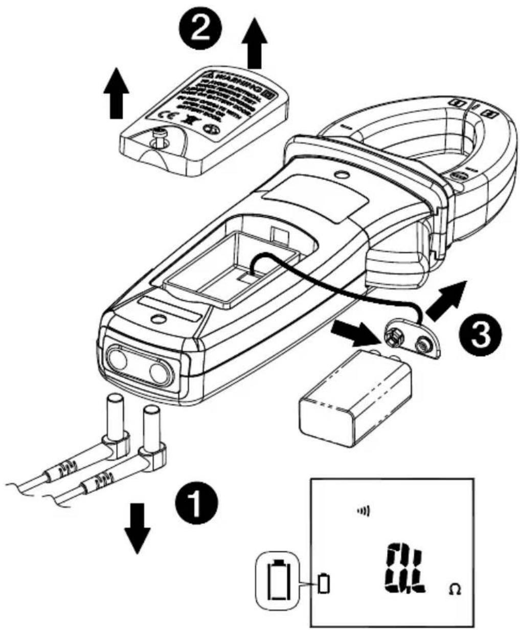
Battery Replacement
- Remove test leads and turn the Meter OFF.
- Loosen the screw from the battery access door of the case. Lift the battery access door and thus the battery compartment up.
- Replace the battery (9V alkaline battery NEDA1604A, JIS6AM6 or IEC6LF22).
- Put the battery access door back and re-fasten the screw.
CAUTION
Remove test leads from Meter before opening the battery cover or Meter case.
AMPROBE®
ACD-50NAV
Pince de navigation 600 A c.a.
ACD-51NAV
Amprobe Test Tools Amprobe Test Tools
Everett, WA 98203 Mississauga, ON L4Z 1X9
Tél : 888-993-5853 Tél : 905-890-7600
Fax: 425-446-6390 Fax: 905-890-6866
Min/Moy/Max (MAX/MIN/AVG) 9
Sous tension
Arrêt automatique
Min/Moy/Max (MAX/MIN/AVG)
Avertisseur
(7) Puissance active : Watt (c.c./c.a.)
V c.c. ≧ 10V, A c.a. ≧ 5 A
ATTENTION
Einschalten
Summer
Freq. 50 \~ 60 Hz, PF = 1,00
DCW (nur ACDC-52NAV, ACDC-54NAV):
DCV ≧ 10 V, DCA ≧ 5 A
⚠ VORSICHT
Amprobe Test Tools Amprobe Test Tools
Everett, WA 98203 Mississauga, ON L4Z 1X9
Tel: 888-993-5853 Tel: 905-890-7600
Fax: 425-446-6390 Fax: 905-890-6866
Accensione
V DC ≧ 10 V, A DC ≧ 5 A
ATTENZIONE
Amprobe Test Tools Amprobe Test Tools
Everett, WA 98203 Mississauga, ON L4Z 1X9
Tel: 888-993-5853 Tel: 905-890-7600
Fax: 425-446-6390 Fax: 905-890-6866
Encendido
Apagado automático
Indicador acústico
Onda sinusoidal, V CA ≧ 10 V rms, A CA ≧ 5 A rms
Frec. 50 \~ 60 Hz, PF = 1,00
V CC ≧ 10 V, A CC ≧ 5 A
⚠ PRECAUCIÓN
Visit www.Amprobe.com for
- Catalog
- Application notes
• Product specifications - User manuals


- Limited Warranty and Limitation of Liability
- Repair
- In-Warranty Repairs and Replacement – All Countries
- Non-Warranty Repairs and Replacement – US and Canada
- In USA In Canada
- Non-Warranty Repairs and Replacement – Europe
- Amprobe® Test Tools Europe
- Safety Information
- Measurement category:
- ⚠ WARNING
- UNPACKING AND INSPECTION
- FEATURES
- OPERATION
- Power On / Off
- Auto Power Off
- Navigator Key
- Making Basic Measurements
- ⚠️ CAUTION
- Measuring Voltage
- ⚠CAUTION
- AUTO SENSE mode:
- Note:
- PEAK HOLD M (AC mode only)
- Inrush Current (AC mode only)
- DC A ZERO (For ACDC-52NAV, ACDC-54NAV Only)
- Measuring Frequency (AC mode only)
- MAX/MIN/AVG
- Note :
- THD Measurement (AC mode only)
- Individual Harmonic Measurement (AC mode only)
- LPF (AC mode only)
- Measuring Active Power (W) / Power factor (PF)
- Single Phase Power Measurement
- Active power sign :
- Power factor sign :
- Overrange display :
- Three Phase Power Measurement
- Phase Rotation
- The screen will display the result as below:
- ⚠ CAUTION
- Measuring Capacitance
- Measuring μA Current (For ACD-51NAV Only)
- AUTO/MANUAL Range
- HOLD Key
- VoltSense
- Buzzer
- Power-up options
- Battery State display
- SPECIFICATIONS
- Environmental Conditions
- Indoor Use
- Safety Compliance:
- Conductor Size:
- Electrical Specifications
- Voltage
- Current
- Accuracy defined for:
- Frequency
- Sensitivity :
- Total Harmonic Distortion:
- Harmonic distortion measurement:
- Inrush Current:
- Accuracy defined for :
- Continuity check :
- MAINTENANCE AND REPAIR
- Trouble Shooting
- Cleaning and Storage
- Battery Replacement
- CAUTION
- AMPROBE®
- ACD-50NAV
- ACD-51NAV
- Arrêt automatique
- Min/Moy/Max (MAX/MIN/AVG)
- Avertisseur
- ATTENTION
- Summer
- ⚠ VORSICHT
- ATTENZIONE
- Apagado automático
- Indicador acústico
- ⚠ PRECAUCIÓN
- Visit www.Amprobe.com for
Brand : Amprobe
Model : ACDC52NAV
Category : Measuring equipment