
VacuFlush 4806 - Toilet DOMETIC - Free user manual and instructions
Find the device manual for free VacuFlush 4806 DOMETIC in PDF.
| Brand | Dometic |
| Model | VacuFlush 4806 |
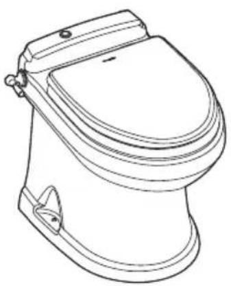
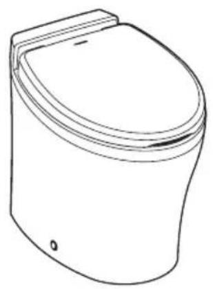
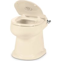
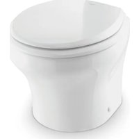
| Product type | Vacuum toilet for boat or RV |
| Power supply | 12 V DC (via vehicle electrical system) |
| Bowl material | Porcelain |
| Flush type | Vacuum pump (VacuFlush system) |
| Flush modes | Normal (adds 0.95 L of water) and dry bowl |
| Bidet function | Yes (model 4800), with hot/cold water adjustment |
| Indicator lights | Green (power on), Orange (tank 75%), Red (tank full) |
| Water consumption per flush | Approximately 0.95 liters (normal mode) |
| Service and maintenance | Clean with non-abrasive products; monthly preventive maintenance |
| Winterization | Potable water antifreeze recommended |
| Safety | Close water valves when away; flood risk |
| Common replacement parts | Ball seal, flush ball, water valve, duckbill valves |
| Warranty | Limited warranty (see Dometic website) |
| Country of origin | United States |
| Approximate dimensions (L x W x H) | 40 x 35 x 45 cm (estimated) |
| Approximate weight | 15 kg (estimated) |
| Applicable standards | ANSI/NFPA 70, ABYC, CSA Z240 |
| Operating temperature | Freeze protection: drain required below 0°C |
Frequently Asked Questions - VacuFlush 4806 DOMETIC
User questions about VacuFlush 4806 DOMETIC
0 question about this device. Answer the ones you know or ask your own.
Ask a new question about this device
Download the instructions for your Toilet in PDF format for free! Find your manual VacuFlush 4806 - DOMETIC and take your electronic device back in hand. On this page are published all the documents necessary for the use of your device. VacuFlush 4806 by DOMETIC.
USER MANUAL VacuFlush 4806 DOMETIC
Service Center & Dealer Locations
Refer to "7 Customer Service" on page 16.
Form No. 600347476 07/18 | ©2018 Dometic Corporation
Read these instructions carefully. These instructions MUST stay with this product.
CONTENTS
1 Explanation of symbols and safety instructions. 3
2 Intended use 4
3 Operation. 4
4 Maintenance 7
5 Troubleshooting. 9
6 Disposal 16
7 Customer Service. 16
8 Limited warranty. 16
1 EXPLANATION OF SYMBOLS AND SAFETY INSTRUCTIONS
This manual has safety information and instructions to help you eliminate or reduce the risk of accidents and injuries.
1.1 Recognize safety information

This is the safety alert symbol. It is used to alert you to potential physical injury hazards. Obey all safety messages that follow this symbol to avoid possible injury or death.
1.2 Understand signal words
A signal word will identify safety messages and property damage messages, and will indicate the degree or level of hazard seriousness.
WARNING indicates a hazardous situation that, if not avoided, could result in death or serious injury.
CAUTION indicates a hazardous situation that, if not avoided, could result in minor or moderate injury.
NOTICE
is used to address practices not related to physical injury.

indicates additional information that is not related to physical injury.
1.3 Supplemental directives

Read and follow all safety information and instructions to avoid possible injury or death. Read and understand these instructions before use and maintenance of this product. Incorrect operation and maintenance of this product can lead to serious injury. The installation must comply with all applicable local or national codes, including the latest edition of the following standards:
U.S.A.
ANSI/NFPA70, National Electrical Code (NEC)
ANSI/NFPA 1192,Recreational Vehicles Code
- ABYC guidelines for marine installations
Canada
- CSA C22.1, Parts I & II, Canadian Electrical Code
- CSA Z240 RV Series, Recreational Vehicles
1.4 General safety messages
WARNING Failure to obey the following warnings could result in property damage, serious injury, or death:
- This product must be installed and serviced by a qualified service technician.
-
Do not modify this product in any way. Modifi cation can be extremely hazardous.
FLOOD HAZARD: -
Before beginning work on this product, be sure that all electrical power to the unit has been turned off and that seacocks are in the closed or off position.
- For toilets connected to any through-the-hull fittings: always close seacocks when the toilet is not in use (even if boat is unattended for a brief period).
- Instruct all passengers on how to close valves when the toilet is not in use.
- For toilets using fresh water for flushing, disconnect any shoreside or municipal water connections when the boat or RV is unattended for any length of time.
NOTICE
RISK OF PROPERTY DAMAGE. Failure to comply may cause damage to the to
or toilet system.
- Only flush water, bodily wastes, and rapid-dissolving toilet tissue.
- Do not overfill the holding tank, or serious damage can occur to the sanitation system. Overfilling the holding tank can rupture the holding tank, or release tank contents into the bilge.
2 INTENDEDUSE
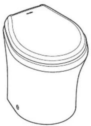
The 4000 Series toilets are designed and intended for use only inside a boat or recreational vehicle (hereinafter referred to as "RV") for which it is supplied. Use the instructions to ensure correct operation of the toilet. Dometic accepts no liability for damage in the following cases:
- Faulty assembly or connection.
- Damage to the product resulting from mechanical influences and excess voltage.
- Alterations to the product without expressed permission from the Dometic Corporation.
- Use for purposes other than those described in the operating manual.
Dometic Corporation reserves the right to modify appearances and specifications without notice.
RV installation is available for certain models only. Refer to the toilet installation manual for information on the applicable models.
3 OPERATION
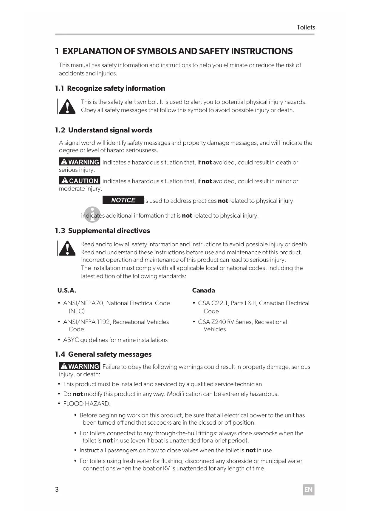
3.1 Using the flush touchpad or flush switches
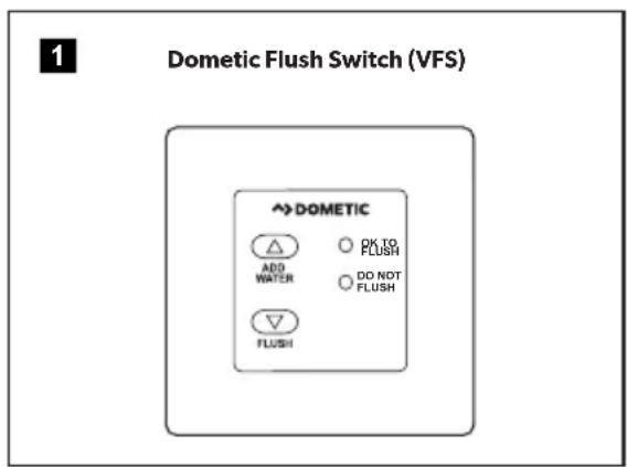
Press and hold the Add Water switch to reach the desired water level.
Press the Flush switch, then release it.
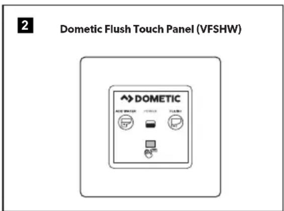
3.2 Using the flush handle (4700 models only)
Lift the flush handle to fill the bowl to the desired water level.
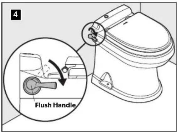
Press the flush handle down, then release it to flush the toilet.
3.3 Understanding the indicator lights for 4500, 4600, 4700, and 4800
Indicator Light Status
Power on Steady green Electrical power to the toilet is
activated
Flashing green The flush mode is changing
Tank level Amber The holding tank is 75% full
Red The holding tank is 100% full*
*Flush actuation is disabled to prevent overfilling the holding tank
3.4 Changing the flush modes for 4500, 4600, 4700, and 4800
Flush modes Action Gallons per flush
Normal Adds water to the bowl after 1 quart (0.95 liters)
every flush
Dry bowl
Does not add water to the
1 pint (0.5 liters)
bowl after every flush
To change modes, press the Flush switch or handle until the power-on light begins flashing (about five seconds).
Release the Flush switch or handle.
3.5 Service Mode
To clean the toilet bowl or seals, or to perform other servicing that requires keeping the flush ball open without running water, use the Service switch.
Push and hold the Service switch for three seconds.
Perform the required servicing.
After servicing is complete, push and hold the Service switch for three seconds to change back to normal operation.
3.6 Initializing the toilet system
Turn on the water supply and electrical power to the toilet and other vacuum system components.
Flush water through the entire vacuum toilet system by flushing the toilet five times (press the Flush handle or switch and allow each flush to complete until the green light indicates that the system is ready for the next flush).
Each cycle takes approximately one minute. If the toilet does not function as expected, refer to "5 Troubleshooting" on page 9 for possible solutions.
3.7 Using the bidet (4800 models only)
WARNING FLOOD HAZARD: Shut the bidet faucet off completely after use. Failure to do so could result in property damage, serious injury, or death.
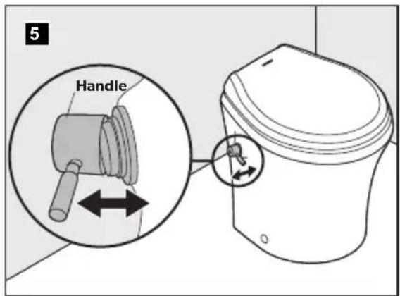
Turn the handle away from the toilet to activate the bidet faucet.
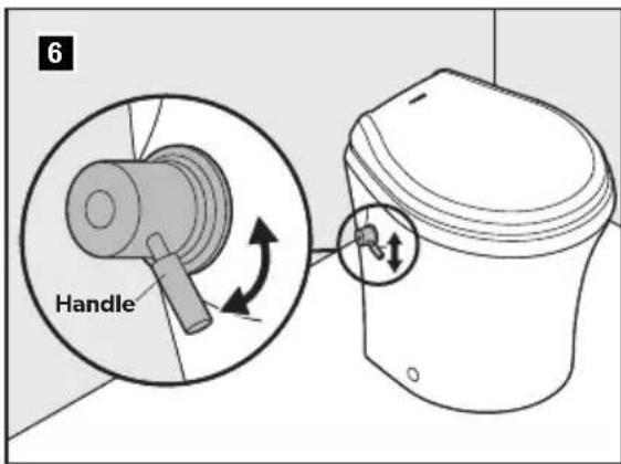
Adjust the water temperature by turning the handle up for warm water, and down for cool water.
Use the electronic flush switch to clear the toilet bowl during and after using the bidet.
3.8 Using the bidet (4500 models only)
WARNING FLOOD HAZARD: Shut the bidet faucet off completely after use. Failure to do so could result in property damage, serious injury, or death.
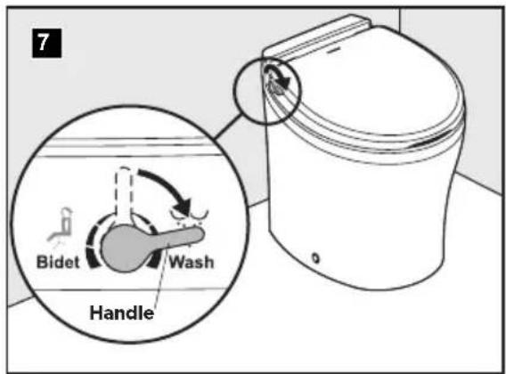
Turn the handle toward the front of the toilet to activate the Wash function.
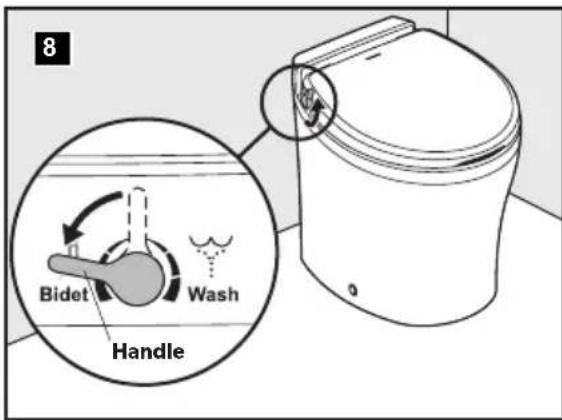
Turn the handle toward the back of the toilet to activate the Bidet function.
4 MAINTENANCE
NOTICE RISK OF PROPERTY DAMAGE: Do not use abrasive cleaners, caustic chemicals, or lubricants and cleaners that contain alcohols or petroleum distillates. These substances may cause damage to the toilet's internal seals.
4.1 Cleaning the toilet
Use non-abrasive cleaners to maintain the original appearance of the toilet.
4.2 VacuFlush system maintenance
Maintenance procedures vary widely and depend on factors such as frequency of use, quality of flushing water, etc. The chart provides a general guideline for keeping your toilet system ready for use at any time.
Maintenance Procedure Service Interval Notes
| ROUTINE | ||
| Check all clamped hose joints below water line for leaks | Monthly — | |
| Check filter screen in water valve | After first year of service, then as needed if water flow is noticeably slower | Screen is located inside water valve inlet |
| Replace vent filter (if installed in holding tank vent line) | Annually — | |
| MAJOR SYSTEM MAINTENANCE | ||
| Replace duckbill valves in vacuum generator or vacuum pump | Every three years See vacuum generator or vacuum pump parts list for replacement kit part number | |
| Replace flush ball seal and flush ball (if required) | Every three years See toilet parts list for replacement kit part number | |
4.3 Recommended spare parts
When operating a boat or other vehicle in remote areas, keep the following spare parts on hand to assure continuous toilet system operation.
| Description Where Used | |
| Flush ball seal | VacuFlush toilet (see parts list) |
| Flush ball | VacuFlush toilet (see parts list). |
| Electric water valve | VacuFlush toilet (see parts list) |
| Vacuum switch kit | Vacuum tank or vacuum generator (see parts list) |
| Duckbill valves | Vacuum tank or vacuum generator (see parts list) |
To order spare parts, refer to "7 Customer Service" on page 16
4.4 Clearing blockage in toilet base
Turn off water to the toilet.
Open the flush ball in Service Mode.
Pull the foreign material from the one-inch diameter orifice at the bottom of the base or, using a small diameter blunt rod, attempt to push the blockage through the orifice.
4.5 Locating potential vacuum leaks in base assembly
The VacuFlush toilet is part of a vacuum system that includes a vacuum pump and vacuum tank, or a vacuum generator and discharge plumbing lines. If a vacuum leak is suspected, special equipment will isolate the source of the leak. If the toilet is determined to be the source of the leak, there are three possible areas to investigate:
Flush ball and flush-ball seal. See "Water does not stay in toilet bowl (leaks between flush ball and seal)" on page 12.
O-rings on the rotor shaft.
O-rings around the bottom of the toilet base assembly.
Sources 1 and 2 will require the base assembly to be removed from the toilet and partially disassembled.
4.6 Preparing the toilet for an extended period of non-use
Toilet system sanitation hoses should be cleared if the toilet will not be used for more than two weeks.
Flush the toilet in Normal Mode.
Add 4 oz. (120 ml) of liquid biodegradable laundry detergent. The detergent should not contain bleach or other environmentally harmful substances.
Open the flush ball in Service mode. Hold the Add Water switch down for about two minutes.
Release the Add Water switch and return the Service Mode switch to the Normal position.
Turn off the water supply to the toilet.
Flush the toilet without water, allowing the vacuum pump to shut off after the flush. Repeat three times. (This procedure will minimize any remaining water in the sanitation hoses.)
Turn off power to the vacuum pump.
Completely pump out the holding tank
If the system will be subjected to freezing temperatures, please follow the above procedure, then proceed to "4.7 Winterizing the toilet" on page 8.
If people will not be using the boat or RV for an extended period of time (vacation, maintenance, off-season, etc.), or in the event of a long electrical power interruption, electrical power and water supply to the toilet and the vacuum generator should be shut off.
4.7 Winterizing the toilet
WARNING RISK OF POISONING: Do not use an automotive-type antifreeze in fresh-water systems. Failure to comply could result in property damage, serious injury, or death.
The amount of antifreeze needed may vary, depending on the installation.
At the end of each season, the VacuFlush toilet system should be winterized for storage. The following procedure should be used:
Thoroughly flush the system with fresh water.
Drain the potable tank.
Empty the holding tank.
Add potable-water antifreeze to the freshwater tank.
Flush the potable-water antifreeze and water mixture through the toilet and into the entire plumbing system. Each installation is different, so amounts may vary. User discretion is required to assure adequate protection.
Turn off power to the toilet and all other vacuum system components.
Empty the holding tank of any remaining contents.
5 TROUBLESHOOTING
5.1 Toilet base assembly
5.2 Troubleshooting
| Fault Possible cause Suggested remedy | ||
| Water does not enter the bowl and the toilet does not flush | Toilet fuse or circuit breaker is tripped | To check the toilet fuse, turn off electrical power to toilet, wait 60 seconds, then turn on the power to the toilet. Check the circuit breaker at the main distribution panel |
| Loose wire connections Check for loose or defective wires at circuit board pins 9 and 10 | ||
| Incorrect wiring of toilet to incoming power | Check for reverse polarity of incoming power | |
| Defective circuit board Replace the circuit board | ||
| Water enters toilet bowl, but toilet does not flush | "OK to Flush" light is not lit on status panel | Check for loose/defective wires between the vacuum switch (on vacuum generator) and wire 6 of the circuit board |
| Electrical failure from flush switch to toilet | Check for loose/defective wires between the flush switch and wires 2 and 4 of the circuit board | |
| Flush switch may be defective Replace if necessary | ||
| Loose flush ball motor wires Check the wires between motor and circuit board wires 17 and 18 | ||
| Defective flush ball motor Replace if necessary | ||
| Flush ball motor drive arm failure. See "Replacing the flush ball" on page 14 | ||
| Drive linkage failure See "Replacing the drive linkage" on page 15 | ||
| Water does not enter toilet bowl, but toilet flushes. | Blocked water supply Clear the blockage in the water line or filter screen at the water valve inlet | |
| Loose/defective wires Check the wires between the water valve and toilet circuit board wires 15 and 16 | ||
| Defective water valve Replace the water valve | ||
| Defective circuit board Replace the circuit board | ||
| Water does not enter toilet when pressing "Add Water" switch. | Electrical failure Check the wires between the "Add Water" switch and circuit board wires 1 and 4 | |
| Defective flush switch Replace the flush switch | ||
| Water does not shut off and toilet bowl overflows. | Debris inside water valve or defective water valve | Replace the water valve |
Fault Possible cause Suggested remedy
| Excessive drag between the flush ball and seal | Clean the surface of the flush ball and under the edge of the seal. Lubricate with alcohol-free cooking spray | |
| Defective spring assembly Replace the spring | ||
| Electrical short circuit Check the wires between “Flush” switch and circuit board wires 2 and 4 | ||
| Flush ball opens slowly | Cam switch needs to be adjusted to align with the flush ball | See “Aligning Cam Switch/Flush Ball” on page 13 |
| Defective cam switch Replace the cam switch. See “Correcting spring assembly, rotor cam shaft, or cam switch” on page 14 | ||
| Defective drive linkage Replace the drive linkage. See “Replacing the drive linkage” on page 15 | ||
| Flush switch must be held in “Flush” position to close flush ball | Service Mode switch is in “Service” position | Return the Service Mode switch to “Normal” position |
| Loose/defective wires Check the wires between cam switch and circuit board wires 11 and 12 | ||
| Defective cam switch Replace the cam switch. See “Correcting spring assembly, rotor cam shaft, or cam switch” on page 14 | ||
| Flush ball does not close completely | Cam switch needs adjustment/ flush ball alignment or replacement | See “Correcting spring assembly, rotor cam shaft, or cam switch” on page 14 |
| Rotor shaft cam is loose or defective | See “Replacing the rotor shaft cam” on page 15 | |
| Flush ball does not open completely. | Rotor shaft cam is loose or defective | See “Replacing the rotor shaft cam” on page 15 |
| Weak or defective spring assembly | Replace the spring | |
| Excessive drag between flush ball and seal | Clean the surface of the flush ball and under the edge of the seal. Lubricate with alcohol-free cooking spray | |
| Squeaky noise occurs during flush cycle. | Lubrication needed between flush ball and seal | Lubricate with alcohol-free cooking spray |
| Lubrication needed between drive arm/linkage joint | Lubricate the joint with silicone grease | |
Fault Possible cause Suggested remedy
| Flush ball seal is worn and needs to be replaced | See “Replacing the flush ball” on page 14 | |
| Water does not stay in toilet bowl (leaks between flush ball and seal) | Flush ball is scratched or worn and needs to be replaced | See “Replacing the flush ball” on page 14 |
| Cam switch/flush ball alignment needs adjustment | See “Aligning Cam Switch/Flush Ball” on page 13 | |
| Bolts that hold base to toilet need tightening to 20-25 in.-lbs | DO NOT OVERTIGHTEN or damage to toilet may occur | |
| Toilet flushes in both “Add Water” and “Flush” positions | Defective circuit board Replace circuit board | |
| Water leaks from toilet onto floor | Loose water line connection Tighten the water line connections | |
| Defective water valve Replace the water valve | ||
| Toilet bowl seal is defective Replace the bowl seal. See “Replacing the flush ball” on page 14 | ||
| Mounting bolts holding base to toilet need tightened to 20-25 in.-lbs | DO NOT OVERTIGHTEN or damage to the toilet may occur | |
| Green “OK to Flush” light does not illuminate | Loose wire at circuit board Check wires 3 and 6 of the circuit board | |
| Loose wire at “Flush” switch Check green wire at the “Flush” switch | ||
| Loose or defective wire between vacuum switch and toilet | Repair or replace the wires | |
| Defective green light Replace the status panel | ||
| Red “Do Not Flush” light does not illuminate | Loose wire at circuit board Check wires 5 and 7 of the circuit board | |
| Loose wire at “Flush” switch Check red wire at the “Flush” switch | ||
| Loose or defective wire between vacuum switch and toilet | Repair or replace the wires | |
| Loose or defective wire between “Full Tank” relay and toilet circuit board pin 8 | Repair or replace the wire | |
| Defective red light Replace the status panel | ||
Fault Possible cause Suggested remedy
| Flush ball opens and closes, but waste does not leave bowl (no vacuum) | No electrical power to vacuum pump | Check power wires, fuse, or circuit breaker to the vacuum pump |
| “Full Tank” shut-down relay prevents vacuum pump from operating | Pump out the holding tank | |
| Blockage inside bottom of toilet base | See “4.4 Clearing blockage in toilet base” on page 8 |
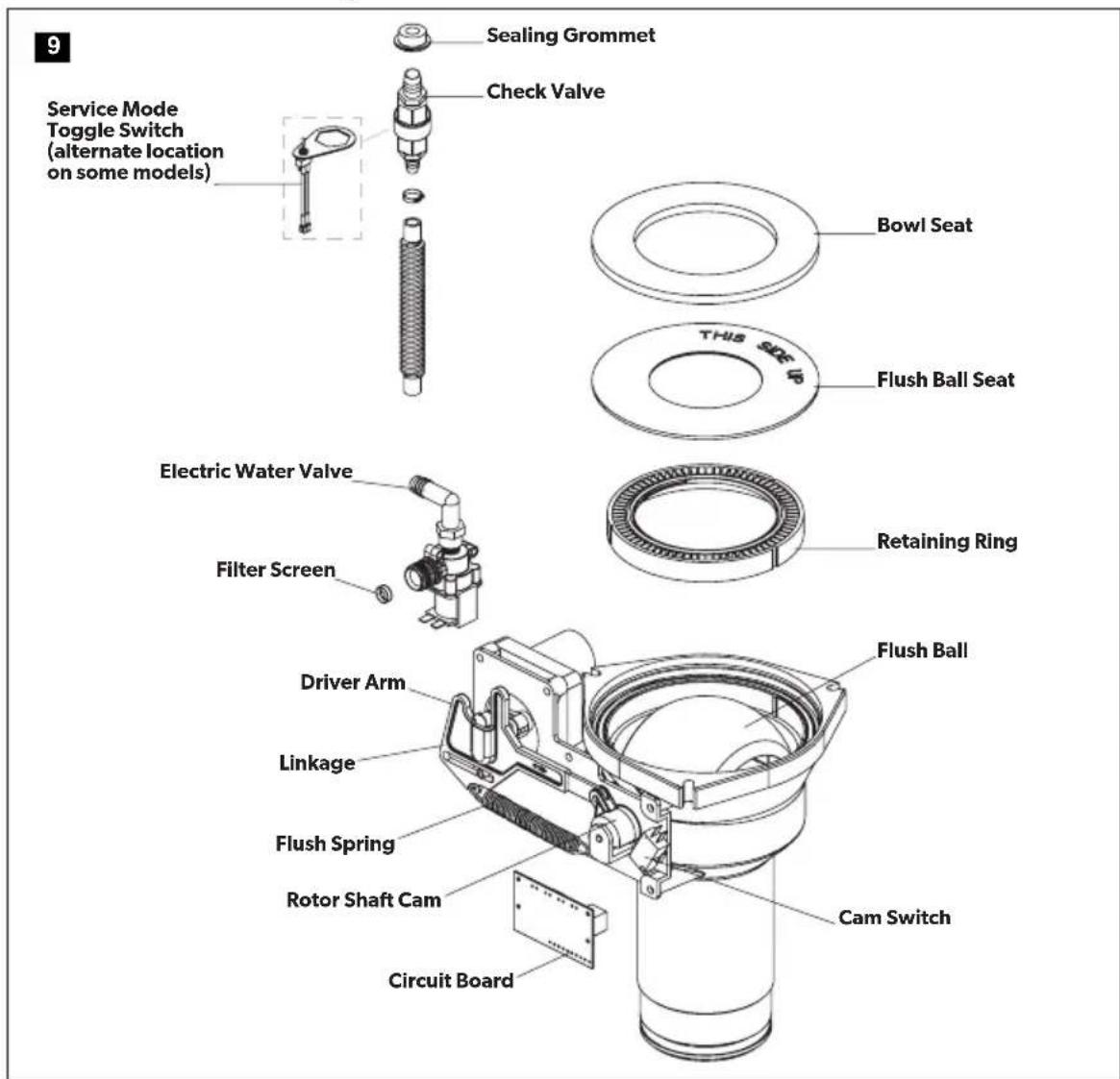
5.3 Servicing the toilet base components
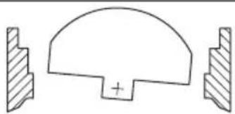
Aligning Cam Switch/Flush Ball
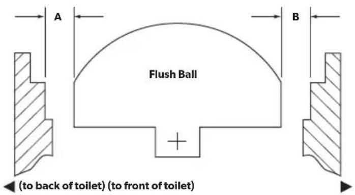
10
The flush ball should be properly positioned so that the "A" and "B" distances are equal (see illustration above). If the flush ball becomes misaligned (resulting in water leaking from bowl or other flushing problems), follow instructions below to resolve problem.
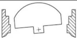
11
Over-travel condition
Under-travel condition
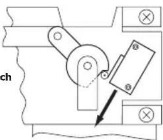
Slide cam switch DOWN
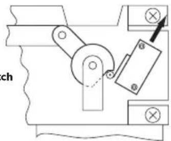
Slide cam switch UP
Removing the toilet from the floor
Turn off the water and the electrical power to the toilet.
Remove the water inlet hose from the toilet.
Remove the toilet from the floor and turn it upside-down.
Make sure the power wires are secure.
Correcting spring assembly, rotor cam shaft, or cam switch
Loosen the cam switch mounting screws with a 3/32-inch hex tool and a 1/4-inch box-end wrench. Slide the cam switch up or down depending on the flush ball position.
Tighten the cam switch mounting screws, apply electrical power and check the adjustment. Repeat as necessary.
After the cam switch and flush ball are properly positioned, connect the water line and reinstall the toilet.
Replacing the flush ball seal
Turn off water and electrical power to the toilet.
Remove water inlet hose from the toilet.
Remove the toilet from the floor and turn it upside-down. Disconnect the service switch wires at the in-line connectors.
Remove the three nuts and flat washers securing the base assembly to the toilet bowl, using a 1/4-inch drive ratchet wrench, 7/16-inch deep-well socket, and an extension.
Pull the check valve or vacuum breaker out of the sealing grommet located in the rear of the toilet bowl.Lift the base assembly from the toilet.
Replace the old seals with a new complete seal kit.
Reconnect the base assembly to the toilet with the new mounting bolts (L-shaped) included with the seal kit. Tighten the nuts to 20-25 in.-lbs. torque.
Reconnect the service switch wires. Reattach the water inlet hose to the toilet.
Reinstall the toilet to the floor.
Replacing the flush ball
Turn off the water to the toilet.
Open the flush ball in Service Mode, then turn off electrical power to the toilet.
Disconnect the water inlet hose.
Remove the toilet from the floor, turn it upside-down, and disconnect the service switch wires at in-line connectors.
Pull the check valve out of the sealing grommet located in the rear of the toilet bowl.
Remove the three nuts and flat washers securing the base assembly to the ceramic toilet bowl, using a 1/4-inch drive ratchet wrench, 7/16-inch deep-well socket, and an extension.
Lift the base assembly from the toilet.
Remove the bowl seal, the flush-ball seal, and the retainer plate to expose the flush ball.
Loosen the set screw in the rotor shaft cam, using a 1/8-inch hex tool.
Remove the #8 x 1/4-inch long screw and flat washer from the linkage slot.Remove the four screws securing the mounting bracket to base.
Pull the mounting bracket and the rotor cam off the base.
Rotate the flush ball forward and remove the flush-ball retaining screw.
Replace the flush ball and reverse the disassembly procedure.
Push the rotor cam all the way onto the rotor shaft. Tighten the set screw.
Lubricate the moving parts with silicone grease.
Before reassembling the entire toilet, the cam switch may require adjustment. See "Aligning Cam Switch/Flush Ball" on page 13.
Replacing the rotor shaft
Follow the disassembly steps in "Replacing the flush ball" on page 14.
Pull the rotor shaft out from inside the base.
Lubricate the O-rings on the new shaft with silicone grease.
Align the flat section on the rotor shaft with the flat section in the ca. Push the rotor shaft cam fully onto the rotor-shaft. Tighten the set screw.
Lubricate moving parts with silicone grease.
Reverse the disassembly procedure.
Before attaching the base to the toilet, the cam switch may require adjustment. See "Aligning Cam Switch/Flush Ball" on page 13.
Replacing the rotor shaft cam
Follow disassembly steps under "Replacing the flush ball" on page 14.
Remove the linkage pin clip and pin.
Attach the new rotor shaft cam to the linkage, using the pin and clip.
Lubricate moving parts with silicone grease.
Reverse the disassembly procedure.
Before attaching the base to the toilet, the cam switch may require adjustment. See "Aligning Cam Switch/Flush Ball" on page 13.
Replacing the motor drive arm
Follow the disassembly steps in "Replacing the flush ball" on page 14.
Remove the four motor-mounting screws.
Remove the motor from the mounting bracket.
Loosen the drive-arm set screw using a 3/32-inch hex tool, then remove the old drive-arm.
Install the new drive arm and push it onto the motor shaft as far as possible. Tighten the set screw.
Lubricate moving parts with silicone grease.
Reverse the disassembly procedure.
Before attaching the base to the toilet, the cam switch may require adjustment. See "Aligning Cam Switch/Flush Ball" on page 13.
Replacing the drive linkage
Follow the disassembly steps in "Replacing the flush ball" on page 14.
Remove the linkage pin clip and pin at the rotor shaft cam.
Remove the flush spring retaining screw and washer from the retaining post.
Remove the flush spring from the old linkage.
Insert the flush spring into the new linkage, and reattach the spring to the retaining post.
Attach the linkage to rotor shaft cam using the pin and clip.
Lubricate moving parts with silicone grease.
Reverse the disassembly procedure.
6 DISPOSAL
Place the packaging material in the appropriate recycling waste bins, whenever possible. Consult a local recycling center or specialized dealer for details about how to dispose of the product in accordance with all applicable national and local regulations.
7 CUSTOMER SERVICE
For the Authorized Service Center near you, call between 8:00 a.m. and 5:00 p.m. (ET), Monday through Friday, or contact the nearest Parts Distributor.
Telephone: 1 800-321-9886 U.S.A. and Canada
330-439-5550 International
Fax: 330-496-3097 U.S.A. and Canada
330-439-5567 International
Website: www.dometic.com
8 LIMITED WARRANTY
LIMITED WARRANTY AVAILABLE AT: dometic.com/warranty.
IF YOU HAVE QUESTIONS, OR TO OBTAIN A COPY OF THE LIMITED WARRANTY FREE OF CHARGE, CONTACT:
DOMETIC CORPORATION
SANITATION CUSTOMER SUPPORT CENTER
13128 STATE ROUTE 226
BIG PRAIRIE, OHIO, USA 44611
+1800-321-9886
SANITAIRE
CUVETTES DE TOILETTE
4500/4600/4700/4800
FR
Serie 4000
3.5 Mode Maintenance

- Service Center & Dealer Locations
- CONTENTS
- EXPLANATION OF SYMBOLS AND SAFETY INSTRUCTIONS
- Recognize safety information
- Understand signal words
- Supplemental directives
- U.S.A.
- Canada
- General safety messages
- NOTICE
- INTENDEDUSE
- OPERATION
- Using the flush touchpad or flush switches
- Using the flush handle (4700 models only)
- Understanding the indicator lights for 4500, 4600, 4700, and 4800
- Indicator Light Status
- Changing the flush modes for 4500, 4600, 4700, and 4800
- Flush modes Action Gallons per flush
- Service Mode
- Initializing the toilet system
- Using the bidet (4800 models only)
- Using the bidet (4500 models only)
- MAINTENANCE
- Cleaning the toilet
- VacuFlush system maintenance
- Recommended spare parts
- Clearing blockage in toilet base
- Locating potential vacuum leaks in base assembly
- Preparing the toilet for an extended period of non-use
- Winterizing the toilet
- TROUBLESHOOTING
- Toilet base assembly
- Troubleshooting
- Fault Possible cause Suggested remedy
- Servicing the toilet base components
- Aligning Cam Switch/Flush Ball
- Removing the toilet from the floor
- Correcting spring assembly, rotor cam shaft, or cam switch
- Replacing the flush ball seal
- Replacing the flush ball
- Replacing the rotor shaft
- Replacing the rotor shaft cam
- Replacing the motor drive arm
- Replacing the drive linkage
- DISPOSAL
- CUSTOMER SERVICE
- LIMITED WARRANTY
- SANITAIRE
- CUVETTES DE TOILETTE
- Mode Maintenance
Brand : DOMETIC
Model : VacuFlush 4806
Category : Toilet