Profile PNRQ21LBN - Water filter GE - Free user manual and instructions
Find the device manual for free Profile PNRQ21LBN GE in PDF.

User questions about Profile PNRQ21LBN GE
0 question about this device. Answer the ones you know or ask your own.
Ask a new question about this device
Download the instructions for your Water filter in PDF format for free! Find your manual Profile PNRQ21LBN - GE and take your electronic device back in hand. On this page are published all the documents necessary for the use of your device. Profile PNRQ21LBN by GE.
USER MANUAL Profile PNRQ21LBN GE
Safety Instructions .....2
Specification Guidelines .....3
Operating Instructions
About the RO System .....4, 5
Installation Instructions
Tools and Materials Required .....6
Before Beginning Installation . . .6, 7
Mounting System Installation .....8
Feed Water Supply .....9–12
Faucet Assembly .....13, 14
Battery Installation .....14
Filtration Drain Connection . .15, 16
Storage Tank and Startup .....17
Care and Cleaning
Prefilter, Postfilter and
RO Cartridge Replacement .....18
Sanitization .....19
Water Test Kit .....20
Troubleshooting Tips .....21-23
Consumer Support
Consumer Support .....Back Cover
Parts List/Catalog .....24, 25
Warranty 26
NSF®
Tested and Certified by NSF International to NSF/ANSI Standard 58. For the reduction of the claims specified, see the Performance Data Sheet.
Write the model and serial numbers here:
Model # ____
Serial # ____
You can find them on the bracket.
Owner's Manual and Installation
PNRQ21LBN
PNRQ21LRB
Osmose Inversée
natural_image
Abstract decorative swirl design with no text or symbols101710 215C1174P007 49-50214 05-06 JR
IMPORTANT SAFETY INFORMATION. READ ALL INSTRUCTIONS BEFORE USING.
⚠ WARNING!
For your safety, the information in this manual must be followed to minimize the risk of property damage or personal injury.

SAFETY PRECAUTIONS
■Check with your state and local public works department for plumbing and sanitation codes. You must follow these guidelines as you install the Reverse Osmosis system. Using a qualified installer is recommended.
■If house water pressure is over the maximum (120 pounds per square inch), install a pressure reducing valve in the water supply line to the Reverse Osmosis system.
■ Be sure the water supply conforms with the Specification Guidelines. If the water supply conditions are unknown, contact your municipal water company or your local health department for a list of contaminants in your area and a list of laboratories certified by your state to analyze drinking water.
A WARNING: Before using the Reverse Osmosis system for the first time, the system must be purged. The Reverse Osmosis cartridge contains a food grade preservative that must be purged from the system. The preservative will give product water an unpleasant taste and odor.
A water an implesant taste and odor. WARNING: Do not use with water that is microbiologically unsafe or of unknown quality
without adequate disinfection before or after the system. Systems certified for cyst reduction may be used on disinfected water that may contain filterable cysts.
This system has been tested for the treatment of water containing pentavalent arsenic (also known as As(V), As(+5) or arsenate) at concentrations of 0.050 mg/L or less. This system reduces pentavalent arsenic, but may not remove other forms of arsenic. This system is to be used on water supplies containing a detectable free chlorine residual or on water supplies that have been demonstrated to contain only pentavalent arsenic. Treatment with chloramine (combined chlorine) is not sufficient to ensure complete conversion of trivalent arsenic to pentavalent arsenic. Please see the Arsenic Facts section of the Performance Data Sheet for further information.
This reverse osmosis system contains a replaceable component critical to efficiency of the system. Replacement of the reverse osmosis component should be with one of identical specifications, as defined by the manufacturer, to assure the same efficiency and contaminant reduction performance.

PROPER INSTALLATION AND MAINTENANCE
This Reverse Osmosis system must be properly installed and located in accordance with the Installation Instructions before it is used.
■Install or store where it will not be exposed to temperatures below freezing or exposed to any type of weather. Water freezing in the system will damage it. Do not attempt to treat water over 100^ F.
■ Do not install on HOT WATER. The temperature of the water supply to the Reverse Osmosis system must be between the minimum of 40^ F and the maximum of 100^ F. See the Specification Guidelines.
■Extended non-use of the Reverse Osmosis system. If the system has not been used for one week or more, open the RO water faucet and allow the system to drain. Close the RO water faucet and allow the system to regenerate the water supply.
■Recommended installation is under the sink. However, the unit can be installed in a remote location, up to 20 feet away from the sink.
- However, additional materials will be required, including additional tubing and extension phone cable. This extension phone cable must be 6 conductor wire and connectors; typical 4 conductor wire will not work. See parts list to obtain additional materials from GE.
- Locating the tank on a basement floor, with the faucet at a first floor sink may result in some loss of flow rate and capacity (approximately 20% ).
Installing a second tank will improve this performance. An RVKIT can be used.
■If Reverse Osmosis system is connected to a refrigerator icemaker, a special icemaker connection kit is required (RVKIT). Do not use copper tubing for the connection between the Reverse Osmosis system and the refrigerator.
⚠️WARNING: Discard all unused parts and packaging material after installation. Small parts remaining after the installation could be a choke hazard.
■ Sanitize upon installation of the Reverse Osmosis system and after servicing inner parts, including replacement of prefilter, postfilter and Reverse Osmosis cartridge. It is important to have clean hands while handling inner parts of the system. See the Sanitizing the Reverse Osmosis System section.
This Reverse Osmosis system contains a replaceable treatment component critical for effective reduction of total dissolved solids. This product water shall be tested periodically to verify that the system is performing satisfactorily. See the About the Water Test Kit section.
BE SURE TO FOLLOW ALL APPLICABLE STATE AND LOCAL CODES.

READ AND FOLLOW THIS SAFETY INFORMATION CAREFULLY.
SAVE THESE INSTRUCTIONS
Product – height 11" width 10.5" depth 4"
The system makes a good supply of drinking water each day.
How much it will make depends primarily on these things...
Feed water pressure limits—pounds per square inch (psi) .....40–120 ^a
Feed water temperature limits—minimum/maximum degrees F .....40–100
Maximum Total Dissolved Solids (TDS)—parts per million (ppm) .....2000
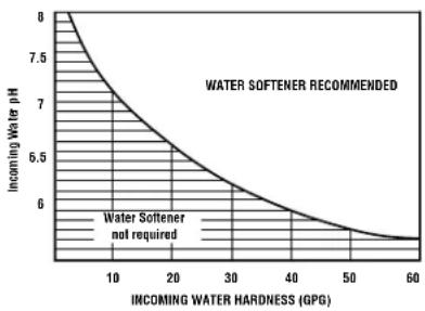
Maximum water hardness @ 6.9 pH recommended to optimize membrane
life—grains per gallon (gpg)....10
For water with hardness greater than 10 grains (at 6.9 pH), the use of a softener is recommended. Failure to install a water softener will reduce the life of the Reverse Osmosis membrane. See chart for additional information on the possible need for a water softener.
area
| INCOMING WATER HARDNESS (GPG) | INCOMING WATER pH | |---|---| | 0 | 8.0 | | 10 | 7.2 | | 20 | 6.8 | | 30 | 6.4 | | 40 | 6.1 | | 50 | 5.9 | | 60 | 5.8 |Maximum iron, manganese, hydrogen sulfide (ppm) ....<0.1
Chlorine in water supply 2.0 ppm Maximum Allowable ^b
Feed water pH limits (pH) 4–10
Storage tank capacity—gallons 4 ^c
Automatic shutoff control ....yes
Prefilter and postfilter (FQROPF) Carbon Block
Reverse Osmosis membrane ....(FQROMF) Thin Film Polyamide
Storage Tank Dimension (inches) . . . . . . . . . . . . . . . . . . . . . . . . . . . . . . . . . . . . . . . . . . . . . . . . . . . . . . . . . . . . . . . . . . . . height 15" diameter 11"
System Body Dimension (inches) . . . . . . . . . . . . . . . . . . . . . . . . . . . . . . . . . . . . . . . . . . . . . . . . . . . . . . . . . . . . . height 11" width 10.5" depth 4"
a. If house water pressure is over 120 psi, install a pressure reducing valve in the water supply line. If house water pressure is under 40 psi, install a Reverse Osmosis booster pump (contact your local plumbing supply company).
b. Removed (maximum of 2.0 ppm) by the Reverse Osmosis prefilter. REGULAR MAINTENANCE IS REQUIRED. Chlorine will destroy the Reverse Osmosis membrane.
c. Theoretical tank capacity. When tested according to NSF/ANSI Standard 58 at 50 psig inlet pressure, tank capacity is 2.3 gallons.
About the reverse osmosis system.
How the Reverse Osmosis System Works
Reverse Osmosis reduces Total Dissolved Solids (TDS) and organic matter from water by diffusing it through a special membrane. The membrane separates minerals and impurities from the water and they are flushed to the drain. For the reduction of the claims specified, see Performance Data Sheet. High quality product water goes directly to the drinking water faucet or to the storage tank. The system makes a good supply of drinking water each day. How much it makes depends on the feed water supply pressure, temperature and quality.
The prefilter and postfilter are replaceable cartridges. The carbon prefilter reduces chlorine while also filtering sediments. The postfilter reduces any other undesirable tastes and odors before you use the water.
These systems include an electronic faucet assembly with a prefilter and postfilter change reminder, Reverse Osmosis membrane change reminder and a status okay reminder.
The prefilter and postfilter change reminder will flash amber after six months have passed or 900 gallons have been used. When this occurs, it is time to replace these cartridges and sanitize the system.
The membrane change reminder flashes amber when the TDS monitor in the system has measured the amount of impurities removed is less than 75%. When this occurs, it is time to replace this Reverse Osmosis membrane cartridge and sanitize the system.
Finally, a green flashing light will indicate the system is functioning properly.
Description of the Reverse Osmosis System
7 Prefilter—Water from the cold supply pipe is directed to the prefilter cartridge. The prefilter is a replaceable sediment cartridge containing activated carbon. The prefilter reduces chlorine in the feed water because CHLORINE DESTROYS THE REVERSE OSMOSIS MEMBRANE. Filtered, clean, chlorine-reduced water flows from the prefilter to the Reverse Osmosis cartridge.
2 Reverse Osmosis Cartridge—The middle cartridge includes a tightly wound, special membrane. Water is forced through the cartridge where the membrane reduces the dissolved solids and organic matter. For the reduction of the claims specified, see Performance Data Sheet. High quality product water exits the Reverse Osmosis cartridge and goes to the storage tank. Reject water, with the dissolved solids and organic matter, leaves the cartridge and is discharged to the drain through 1/4" tubing.
3 Postfilter—After leaving the storage area, but before going to the system faucet, product water goes to the postfilter cartridge. The postfilter is also a replaceable sediment cartridge that contains activated carbon. Any remaining tastes, odors or sediments are reduced from product water by the postfilter. Clean, high quality drinking water flows through the tubing and to the system faucet.
4 Storage Tank—The storage area holds up to 2-1/2 gallons of product water. A diaphragm inside the tank keeps water pressurized, when the tank is full, for fast flow to the faucet when drinking water is needed.
natural_image
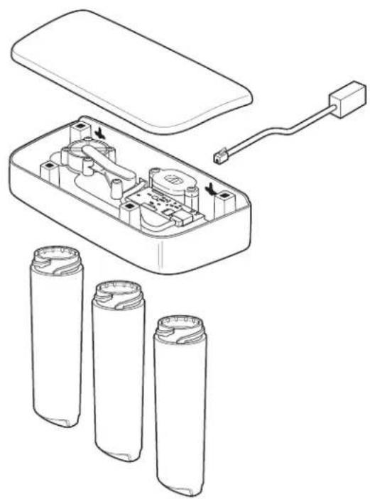
Diagram of an open battery pack with internal components and three cylindrical batteries, showing wiring connections (no text or labels)5 Check Valve—The check valve prevents a backward flow of product water from the storage tank. A backward flow could cause the Reverse Osmosis membrane to rupture.
6 Automatic Shutoff Assembly—To conserve water, the drinking water system has an automatic shutoff. When the storage tank has filled to capacity and the drinking water faucet is closed, pressure closes the shutoff. Water flow to the Reverse Osmosis housing is shut off until drinking water is used again, and pressure drops in the Reverse Osmosis system.
7 Flow Control—The flow control regulates the flow of water through the Reverse Osmosis cartridge at the required rate to produce high quality water. The control is located in the 1/4" drain line exiting off the manifold.
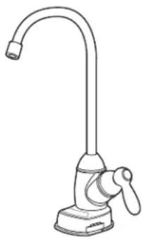
8 Faucet and Electronics—The countertop faucet dispenses filtered drinking water when opened. It has a hand-operated lever, with variable flow adjustment. You can keep the faucet open by removing your hand from the lever once water is flowing. To comply with plumbing codes, an air gap is built into the faucet drain water connection.
natural_image
Line drawing of a standard kitchen faucet with handle and base (no text or symbols)The electronic faucet provides a six month timer and flow monitor to remind you when it is time to replace your prefilter and postfilter. Replace these when the amber filter light flashes. The faucet also provides an amber RO light indicating when the Reverse Osmosis cartridge is no longer filtering out at least 75% of the TDS. Replace this cartridge when this amber light flashes. The green flashing light will indicate the system is functioning properly.
Installation Instructions
Reverse Osmosis Filtration System
Models PNRQ21LBN and PNRQ21LRB
Questions? Call 800.GE.CARES (800.432.2737)
⚠ WARNING: Read entire manual. Failure to follow all guides and rules could cause personal injury or property damage.
- Check with your state and/or local public works department for plumbing codes. You must follow their guides as you install the Water Filtration system.
NOTE: Failure to comply with these installation instructions will void the product warranty, and the installer will be responsible for any service, repair or damages caused thereby.
TOOLS AND MATERIALS REQUIRED FOR INSTALLATION
- Electric drill and 1-1/4" Drill Bit (type as required) if mounting is needed for faucet
- Two (2) Adjustable Wrenches
- 1/16" Drill Bit (optional for pilot holes)
- Tape Measure
• Phillips and Flat Blade Screwdrivers - Utility Knife
- If your main water line is a rigid pipe, you will require a compression fitting and possibly other plumbing hardware to complete the installation.
⚠️CAUTION: To avoid damaging the
sink, consult a qualified plumber or installer for drilling procedures. Special drill bits may be needed for porcelain or stainless steel.
BEFORE BEGINNING INSTALLATION
Read these instructions completely and carefully.
- IMPORTANT — Save these instructions for local inspector's use.
• IMPORTANT — Observe all governing codes and ordinances.
- Note to Installer – Be sure to leave these instructions with the Consumer.
- Note to Consumer – Keep these instructions for future reference.
- Proper installation is the responsibility of the installer.
- Product failure due to improper installation is not covered under the Warranty.
- A shutoff valve must be available or added near the installation point.
CONTENTS INCLUDED WITH PRODUCT
- Reverse Osmosis Assembly and Tubing
- Product Literature (Owner's Manual and Installation Instructions)
• Performance Data Sheet - Feed Water Adapter and Supply Valve
- Faucet Assembly with Electronic Base Monitor and Tubing
- Storage Tank
- Drain Line Adapter
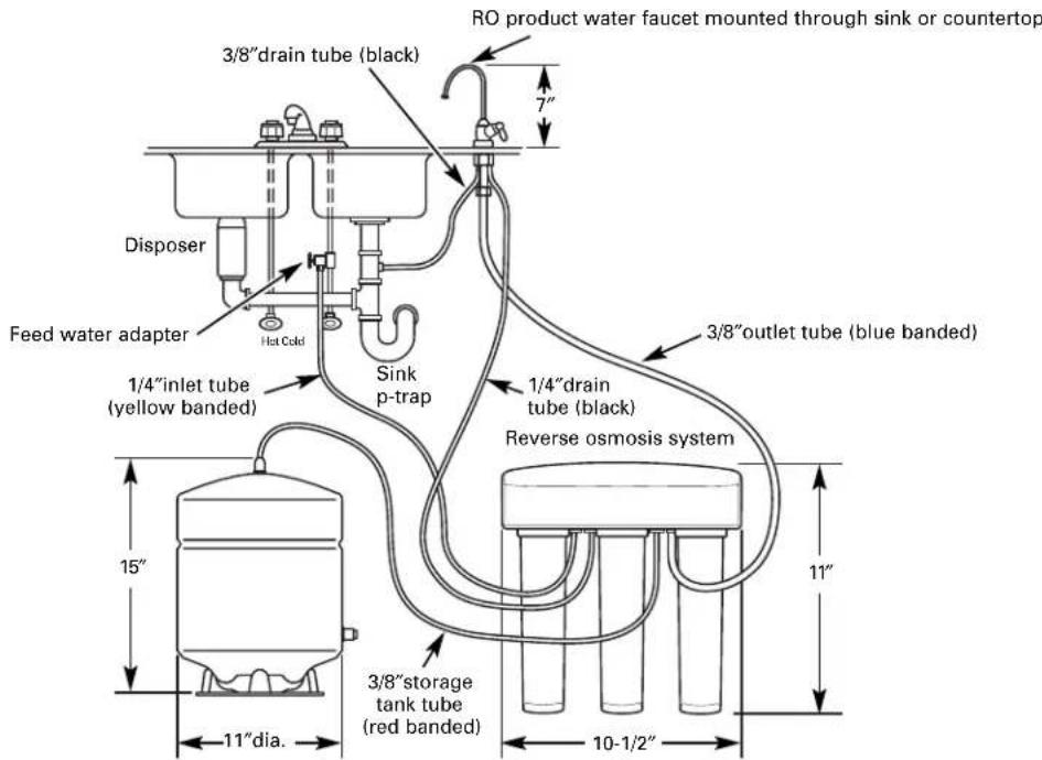
Things to Check Before Beginning Installation
text_image
RO product water faucet mounted through sink or countertop 3/8"drain tube (black) 7" Disposer Hot Cold Feed water adapter 1/4"inlet tube (yellow banded) Sink p-trap 1/4"drain tube (black) 3/8"outlet tube (blue banded) Reverse osmosis system 15" 11" 11"dia. 3/8"storage tank tube (red banded) 10-1/2"TUBING/FILTER DETAIL
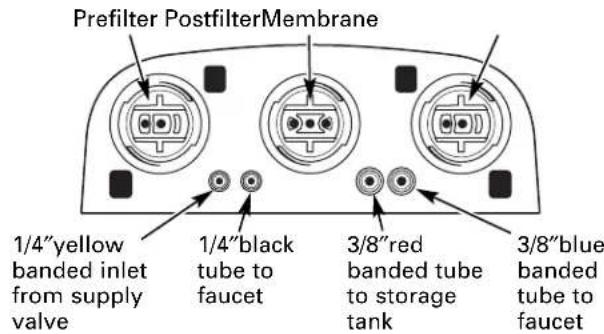
text_image
Prefilter PostfilterMembrane 1/4"yellow banded inlet from supply valve 1/4"black tube to faucet 3/8"red banded tube to storage tank 3/8"blue banded tube to faucetFEED WATER
The water supply to the undercounter Reverse Osmosis system must have the qualities listed in the specifications. Municipal water supplies most often will have these qualities. Well water may need conditioning—have the water tested by a water analysis laboratory and get their recommendations for treatment.
⚠️CAUTION: For water with a hardness greater than 10 grains (at 6.9 pH), the use of a softener is recommended. Failure to install a softener will reduce the life of the Reverse Osmosis cartridge.
FILTRATION DRAIN CONNECTION
A suitable drain point and air gap (check your state and/or local codes) are needed for reject water from the Reverse Osmosis membrane cartridge.
RO FAUCET
The RO product water faucet installs on the sink or on the countertop next to the sink. Often, it is installed in an existing sink spray attachment hole or a hole may be drilled. Space is required underneath for tubing to and from the faucet, and for securing the faucet in place. All faucet connections are done on or above the sink or countertop.
BASEMENT INSTALLATION
If installing in a basement, leave enough tubing in place during installation to be able to move unit to floor for ease at servicing and making filter/membrane changes. Additional tubing and fittings required.
NOTE: See parts list on page 25 for optional parts that may be required for a basement installation.
REVERSE OSMOSIS ASSEMBLY
MOUNTING SYSTEM INSTALLATION
Choose a location under the sink to mount the system. Location should be easily accessible, with adequate clearance between the bottom of the filter cartridges and the floor or bottom of the cabinet for removal of filter cartridges. Allow enough space on either side of the system for the tubing connections.
- Remove the prefilter and postfilter cartridges.
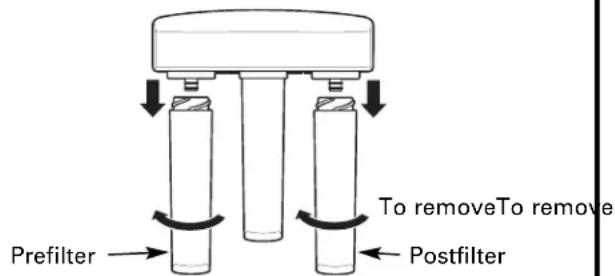
text_image
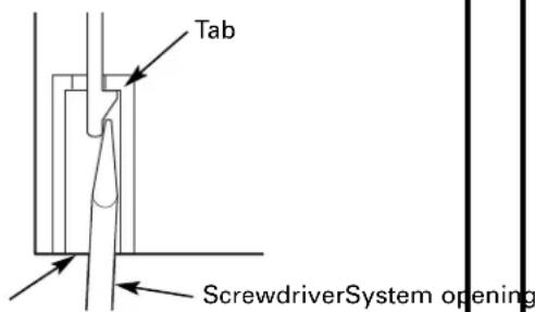
Prefilter To removeTo remove Postfilter- Remove the assembly cover by unlocking the four tabs on the cover from the system.
- Use a flat-head screwdriver to work from left to right from the underside of the system.
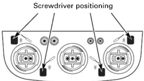
text_image
Screwdriver positioning- Use the icons on the bottom of the system for screwdriver positioning.
text_image
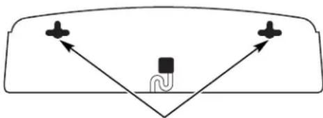
Tab ScrewdriverSystem opening- Hold the Reverse Osmosis assembly up to the wall surface where you wish to install it. Mark location for screws. There should be a minimum of 17 inches from the marks to the bottom of the cabinet floor.
natural_image
Simple diagram showing a car with two directional arrows pointing toward a central body and a curved line, no text or symbols present.Screw locations
⚠️CAUTION: Do not get dirt or debris inside the assembly area. Use only to mark mounting hole locations.
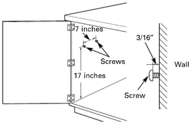
- Install screws to the wall, leaving a 3/16-inch clearance between the head of the screw and wall (drill pilot holes if needed).
text_image
7 inches Screws 17 inches 3/16" Wall Screw- Hang the Reverse Osmosis assembly on the screws. Tighten or loosen the screws as desired until the system is secure on the wall.
- To install the cover, line up the front tabs on the cover with the openings in the system.
- Snap the cover in place; the tabs will flex, allowing the cover to snap in place.
- Remove the membrane cartridge.
natural_image
Technical line drawing of a mechanical component with arrows indicating assembly or movement (no text or symbols)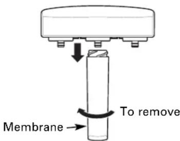
text_image
Membrane To removeFEED WATER SUPPLY
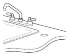
Check and comply with local plumbing codes as you plan, then install a cold feed water supply fitting.
A. PREFERRED INSTALLATION
Utilizing existing kitchen sink water supply valve (A) and removable faucet tubing (B).
- Refer to illustration below to complete assembly depending on supply valve size (A).
- Close the cold water supply valve (A) under the sink.
- Unscrew the flexible tubing line (B) from the supply valve (A) that connects to the COLD water riser.
NOTE: For rigid pipe, see C. Optional Installation on page 10.
Note Adapter (C) orientation:
3/8-inch installation—Rounded end of adapter (C) connects to supply valve (A).
1/2-inch installation—Rounded end of adapter (C) connects to coupling (D), then to existing faucet tubing (B).
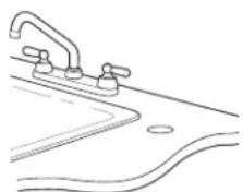
For 3/8" Plumbing
natural_image
Line drawing of a faucet and sink with a curved pipe (no text or symbols)For 1/2" Plumbing
natural_image
Line drawing of a faucet and sink with a curved pipe (no text or symbols)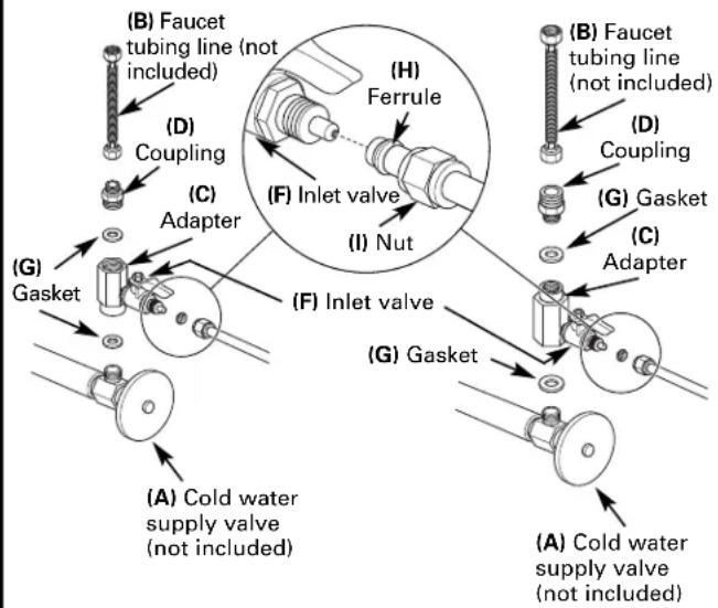
text_image
(B) Faucet tubing line (not included) (D) Coupling (C) Adapter (H) Ferrule (F) Inlet valve (I) Nut (G) Gasket (C) Adapter (F) Inlet valve (G) Gasket (A) Cold water supply valve (not included) (A) Cold water supply valve (not included)- Assemble adapter (C) and coupling (D) as shown in illustration at left, per your configuration. Ensure that the gasket (G) is in place before final assembly. Start installation by hand, then finish tightening with adjustable wrench. Be careful not to overtighten or cross thread as damage to threads may occur.
- Hand tighten assembled adapter (C) onto supply valve (A) for the proper size installation. Be sure gasket (G) is in place before final assembly. Start installation by hand, then finish tightening with an adjustable wrench. Be careful not to overtighten or cross thread as damage to threads may occur.
- Reconnect faucet tubing line (B) to top of adapter (C).
NOTE: If inlet valve (F) is to be removed for installation, refer to E. Removal and Reinstallation of Inlet Valve on page 11.
- Cut wire ties on tubing coils, using care not to damage tubes or parts if using a utility knife.
- Remove the 1/2" nut (I) and ferrule (H) from end of inlet valve. Using the yellow banded tubing provided, place the nut (I) and ferrule (H) onto the tubing and install onto inlet valve (F) as shown at left. Tighten with adjustable wrench. Be careful not to overtighten or cross thread as damage to threads may occur.
NOTE: Inspect the ends of the tubing prior to installation to be sure there are no imperfections and that the end of the tubing is cut square. It may be necessary to cut the tubing again.
FEED WATER SUPPLY (cont.)
B. OPTIONAL HOME INSTALLATION
Where codes permit (Requires additional parts)
*For 1/2"OD or larger metal tubing only.
NOTE: Codes in the state of Massachusetts require installation by a licensed plumber and do not permit the use of the saddle valve. For installation, use plumbing code 248-CMR of the Commonwealth of Massachusetts.
Saddle valve is available through GE Parts and Services at 1.800.626.2002, part number WS15X10023. Self piercing saddle valves are not recommended.
- Turn off the cold water supply and attach saddle valve as required by product selection. (Be sure to follow manufacturers' Installation Instructions).

DANGER: Many homes are
electrically grounded through the plumbing. To protect yourself from serious injury or fatal shock, use a battery-powered hand drill only to make the hole. DO NOT USE AN ELECTRIC DRILL.
- Close the water supply valve by turning the handle clockwise.
- Open the main water supply valve and several house faucets to purge air from the system. Close faucets when water runs smoothly.
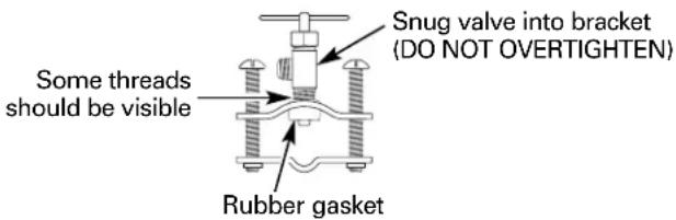
text_image
Some threads should be visible Snug valve into bracket (DO NOT OVERTIGHTEN) Rubber gasketOptional water supply connection (using saddle valve)*
*For 1/2 "OD or larger metal tubing only.
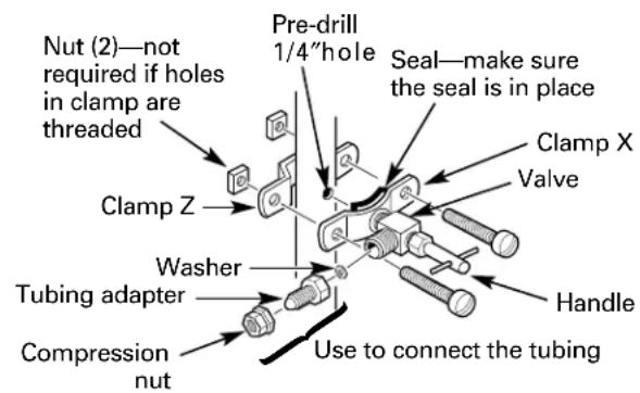
text_image
Nut (2)—not required if holes in clamp are threaded Clamp Z Washer Tubing adapter Compression nut Pre-drill 1/4"hole Seal—make sure the seal is in place Clamp X Valve Handle Use to connect the tubingC. OPTIONAL RIGID PIPE INSTALLATION
For installation with rigid pipe between supply valve and sink faucet.
Option 1
- Remove pipe from supply valve and sink faucet.
- Obtain flexible pipe sized to your plumbing.
- Install flexible pipe.
- GO back to A. Preferred Installation section, step 4.
Option 2
- Obtain compression fittings to fit rigid pipe.
- Obtain any other fittings required to connect compression fittings to adapter.
NOTE: Adapter has 1/2-inch and 3/8-inch internal and external threads.
-
Remove pipe from supply valve.
-
Cut pipe to fit length of assembled fittings and adapter.
-
Install compression fitting to pipe.
-
GO back to A. Preferred Installation section, step 4.
NOTE: Above described materials are not included with the product.
D. OPTIONAL REMOTE LOCATION INSTALLATION
(requires additional part)
- Turn off the cold water supply.
- Complying with plumbing codes, install a fitting on the cold water pipe to adapt 1/4" OD tubing. A typical connection is shown in illustration below. Make sure a water supply valve is used.
- If the RO unit is to be installed more than 6 feet from the valve, replace the yellow banded inlet tubing with a longer length of GE 1/4" tubing. A 33 foot length of 1/4" tubing is available through GE Parts and Services at 1.800.626.2002, part number WS07X10018. DO NOT SUBSTITUTE TUBING OF UNKNOWN QUALITY.
- If the RO unit is to be installed more than 6 feet from the faucet, replace the blue banded outlet tubing with a longer length of GE 3/8" tubing. A 33 foot length is available through GE Parts and Services at 1.800.626.2002, part number WS07X10019. See Faucet Installation on page 13 for more details. DO NOT SUBSTITUTE TUBING OF UNKNOWN QUALITY.
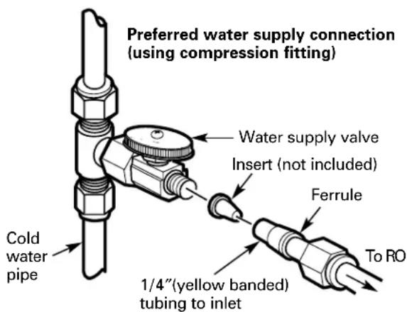
text_image
Preferred water supply connection (using compression fitting) Water supply valve Insert (not included) Ferrule Cold water pipe 1/4"(yellow banded) tubing to inlet To ROIf you are using copper tubing, DO NOT connect it directly onto the RO unit. Purchase a connector and use a short length of the yellow banded tubing provided to make final connection to RO. Do not use copper tubing to attach to icemaker or faucet.
E. REMOVAL AND RE-INSTALLATION OF INLET VALVE (required only if inlet valve needs to be removed to complete Step 5 on page 13)
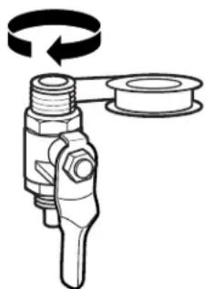
- Remove inlet valve (F) from adapter (C) using adjustable wrench on valve body. See illustration below for detail. DO NOT USE WRENCH ON HEX NUT END OF VALVE AS LEAK MAY OCCUR.
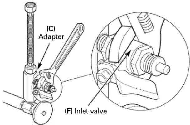
text_image
(C) Adapter (F) Inlet valve- Remove all sealing tape from inlet valve (F) and adapter (C) threads.
- Hand tighten assembled adapter (C) onto supply valve (A) for the proper size installation. Be sure the gaskets (G), as shown on page 13, are in place before final assembly. Finish tightening with adjustable wrench. Be careful not to overtighten or cross thread as damage to threads may occur.
- Using white thread sealing tape provided, apply approximately 9 wraps of tape around the large threads on inlet valve (F) in a clockwise direction, as shown below.
natural_image
Mechanical component diagram showing a pulley and threaded shaft assembly (no text or symbols)- Hand tighten inlet valve (F) into the adapter (C), then finish tightening with adjustable wrench. DO NOT USE WRENCH ON HEX NUT END OF VALVE AS LEAK MAY OCCUR.
TUBING AND FLOW RESTRICTOR INSTALLATION
INSTALLING THE TUBING TO TANK AND FAUCET
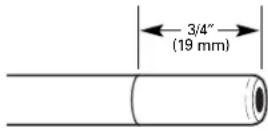
- Measure 3/4" from the end of each remaining piece of tubing (faucet end and inlet end) and mark with a pencil. (Check for roundness, smoothness, cuts, nicks, flat spots and sharp edges).
INCORRECT
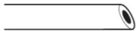
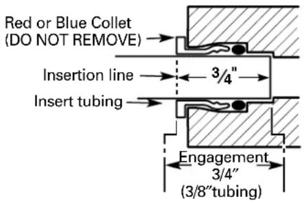
- Push the tubing firmly into each fitting on the manifold until the line is flush with the fitting collar. (If the tubing is removed, re-cut the end, measure, mark and re-insert). Tubing must be fully inserted to avoid leaks. To remove tubing: depress and hold red or blue collet; pull tubing out to remove.
text_image
Red or Blue Collet (DO NOT REMOVE) Insertion line 3/4" Insert tubing Engagement 3/4" (3/8"tubing)- Pull out slightly on tubing to ensure a good seal.
FLOW RESTRICTOR REPLACEMENT PROCEDURE
Each time the Reverse Osmosis cartridge is changed, you will need to replace the flow restrictor in the drain line as well.
Be sure to wash your hands before handling inner parts of the system.
FLOW RESTRICTOR REPLACEMENT PROCEDURE (cont.)
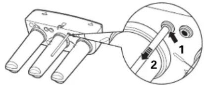
- Remove drain line tubing by pushing up on the drain line collet with one hand (1) and removing the drain line with the other hand (2).
text_image
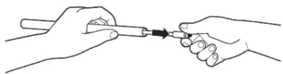
Technical diagram showing a mechanical assembly with labeled parts 1 and 2, including a magnified inset view.- Once the drain line has been removed from the system base, grasp the end of the flow restrictor and pull it straight out from the tube*. If the restrictor is difficult to remove by hand, a pair of pliers may be used to grip the end of the restrictor to aid in removal from the tubing.
natural_image
Line drawing of two hands holding a tool with an arrow indicating direction (no text or symbols)*In some instances, the restrictor may slide out of the drain tubing as it is removed from the drain line port. If, after removing the drain line as described in step 1, the restrictor is no longer in the end of the tubing, check the drain line port. Remove the restrictor from the port and proceed to step 3.
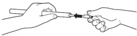
- Take new restrictor and slide it back into the drain tubing. Insert the restrictor by hand only. Do not use pliers to insert. Make sure to insert restrictor all the way into the tubing. Failure to do so could result in improper operation of the RO system.
natural_image
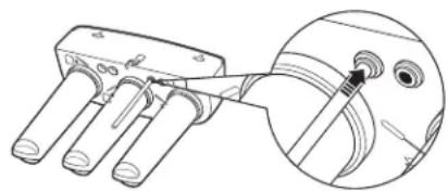
Line drawing of two hands holding a tool with an arrow indicating direction (no text or symbols)- Reinsert drain line tubing in system base. Tug lightly on the tubing to ensure that the collet is engaged and has a proper grip on the tubing.
natural_image
Technical line drawing of a mechanical component with three pins and a magnified inset showing internal structure (no text or symbols)FAUCET ASSEMBLY
FAUCET MOUNTING INSTALLATION
Be sure there is room underneath the sink to make the needed connections. Select one of the following locations to install the faucet:
- In an existing sink spray attachment or soap dispenser hole.
- In a hole to be drilled in the sink top.
- In a hole to be drilled in the countertop, next to the sink.
NOTE: Be sure the faucet base will fit flat against the surface at the selected location so the gasket will seal.
-
If drilling is needed, make a 1-1/4" dia. hole. Be sure to use the proper procedure for drilling porcelain or stainless steel. Special drill bits may be needed. Consult a qualified plumber for proper procedure.
-
Remove the faucet, thin o-ring (D), faucet base (E), bottom base gasket (F), lock washer (G), hex nut (H) and mounting bracket (I) from the packaging.
-
Feed the 3/8" blue banded, 1/4" black tube (attached to the Reverse Osmosis System) and the 3/8" black tube (included in separate packaging) up through the mounting hole in the sink or countertop. This step may require two people to assemble. See page 14 for Optional One Person Faucet Tubing Installation.
-
Feed the two black tubes up through the gasket (F), faucet base (E) and O-ring (D).
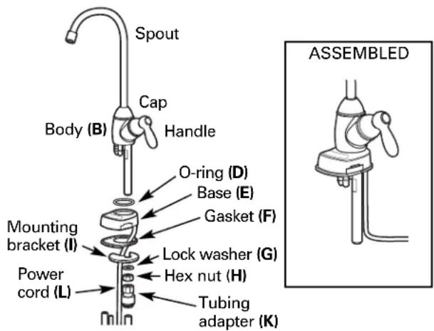
text_image
Spout Cap Handle Body (B) O-ring (D) Base (E) Gasket (F) Mounting bracket (I) Lock washer (G) Power cord (L) Hex nut (H) Tubing adapter (K) ASSEMBLEDNOTE: For ease of service and maintenance, keep tubing lengths long enough so removal of the Reverse Osmosis system from under the sink is possible.
- Push the 1/4" black and 3/8" black tubing onto their respective fittings on the body (B).
NOTE: To ease insertion, submerge tubing ends into hot water for a few minutes to soften.
-
Seat the base (E) and body (B) together. Make sure the O-ring and gasket are in place when the base meets the body. The faucet handle will be at the 3 o'clock position with respect to the base.
-
Slide the lock washer onto the threaded stem of the body (B), then thread the hex nut (H) onto the stem. Screw about halfway up.
NOTE: If installing faucet on a stainless steel sink, slide on installation spacer (M) before the lock washer.
-
Screw the blue tipped tubing adapter (K) onto the threaded stem of the body (B).
-
Push the blue banded tubing into the adapter. It should go in about 3/4". Pull on it to make sure it is installed correctly.
-
Feed the tubing, stem and power cord back down through the 1-1/4"hole.
-
Lower the faucet assembly into place in the mounting hole and orient to final position. Place the mounting bracket (I) above the lock washer (G) around the faucet stem. While holding the mounting bracket in place, securely tighten the hex nut. This step may require two people.
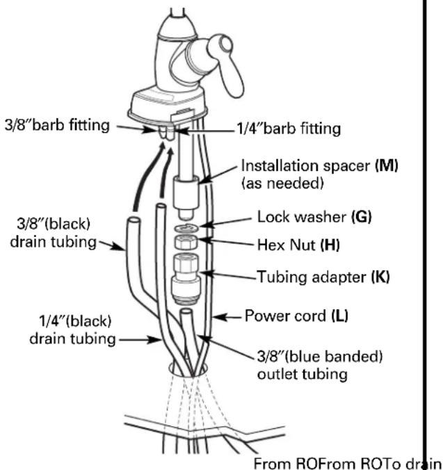
text_image
3/8"barb fitting 1/4"barb fitting Installation spacer (M) (as needed) 3/8"(black) drain tubing Lock washer (G) Hex Nut (H) Tubing adapter (K) Power cord (L) 1/4"(black) drain tubing 3/8"(blue banded) outlet tubing From ROFrom ROTo drainFAUCET ASSEMBLY (cont.)
OPTIONAL ONE PERSON FAUCET TUBING INSTALLATION
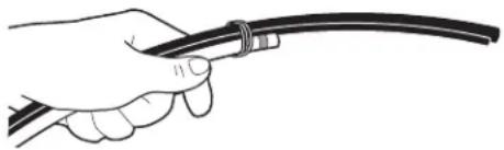
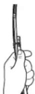
- From under the sink, gather the 1/4" drain line (black), 3/8" drain line (black) and 3/8" outlet tube (blue banded) in one hand with the drain tubes the same length and the outlet tube offset approximately 6 inches.

natural_image
Illustration of a hand holding a cable or wire (no text or symbols)- Wrap a rubber band around all 3 tubes.
natural_image
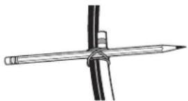
Illustration of a hand holding a cable with a flexible wire (no text or symbols)- Insert a typical No. 2 pencil through the rubber band location.
natural_image
Simple line drawing of a pencil tied with a vertical rod, no text or symbols present- Rotate the pencil down until it is in line with the tubing and push up through the mounting hole. Release the grip on the pencil and the tubes will remain in position for easier faucet connection.
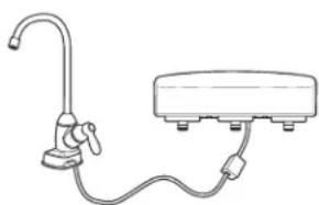
POWER CORD INSTALLATION
Connect power cord from faucet to union outlet from the Reverse Osmosis Assembly.
NOTE: If extension cord is required for a remote location, this extension phone cable must be 6 conductor wire and connectors; typical 4 conductor will not work.
natural_image
Line drawing of a kitchen sink with faucet and water dispenser (no text or symbols)BATTERY INSTALLATION
-
Use a small flat blade screwdriver or coin to remove the battery tray (A) at the side of the faucet base.
-
Install one CR2032, 3 volt battery (B) positive "+" side down into the battery tray (A).
-
Slide tray into faucet base (C) until the battery tray (A) edge is flush with the side of the base.
-
Each light will illuminate in sequence twice. At the end, the OK (green) light or filter (yellow) light may stay on for a few extra seconds. If you want to reinitiate the start-up sequence, remove the battery for 90 seconds; the electronics need to fully discharge. Then put the battery back in.
-
The OK (green) light will normally flash one time per second when dispensing water. The filter or RO (amber) lights will flash one time per second when dispensing water if the system needs service. If the system needs service, they will also flash randomly when the system is not in use.
For lights to change between OK and RO, the system must detect a change in the filtering process for 25 consecutive seconds. For example, if the system was not filtering correctly, the RO light would be flashing. When the problem is corrected and the system is filtering correctly, the electronics will wait for 25 seconds to confirm the changes before changing to an OK light.

text_image
(D) Green or amber lights (B) Battery - + (A) Battery tray (C) Faucet baseFOR FILTER CHANGE: Replace battery when changing filter. Remove used battery and wait at least 90 seconds before installing new battery. This will ensure full electronic reset and proper operation for the next 6 months.
FILTRATION DRAIN CONNECTION
Check and comply with local plumbing codes as you plan.
CAUTION: The options detailed below are the ONLY approved installation configurations. Do not use any drain saddle device.
NOTE: Failure to follow these Installation Instructions will void the warranty, and the installer will be responsible for any service, repair or damages caused thereby.
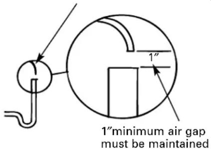
PREFERRED INSTALLATION: OPTION A—BASEMENT ACCESS INSTALLATION
Route the drain line DIRECTLY from the Reverse Osmosis system to a standpipe in the basement, bypassing the air gap provided in the faucet. The air gap installation is left to the discretion of the installer. The drain line may also be routed to a floor drain or washtub, provided that the air gap is maintained. Special air gap fittings are available to connect the drain line to the top of the standpipe.
Drain line from the Reverse Osmosis system
text_image
1" minimum air gap must be maintainedPREFERRED INSTALLATION: OPTION B—DRY-VENTED P-TRAP INSTALLATION
Install a separate dry-vented p-trap under the sink to be used exclusively for the Reserve Osmosis drain line. A dry-vented p-trap is a p-trap that has its own vent/stack. Attach the drain line adapter to the p-trap and secure it with the slip joint nut and washer as shown. The drain line MUST be routed through the air gap provided in the RO water faucet.
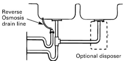
text_image
Reverse Osmosis drain line Optional disposerInstall a p-trap under the sink to be used exclusively for the Reverse Osmosis drain line. A wet-vented p-trap is a p-trap that shares a common vent/stack. Attach the drain line adapter to the p-trap and secure it with the slip joint nut and washer as shown. The drain line MUST be routed through the air gap provided in the RO water faucet. Locate the Reverse Osmosis p-trap as high as possible (minimum of 4" above horizontal).
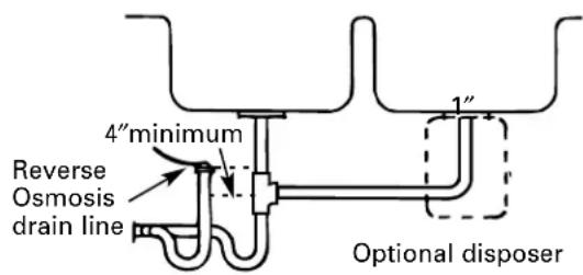
text_image
4" minimum Reverse Osmosis drain line 1" Optional disposerSECONDARY INSTALLATION: OPTION D—DRAIN LINE ADAPTER INSTALLATION
CAUTION: Using Option D may result in clogging under adverse conditions and requires periodic inspection/cleaning by the user.
DO NOT INSTALL THE DRAIN LINE DOWNSTREAM OF A DISPOSER OR IN A HORIZONTAL PIPE. Install the drain line adapter under the sink as shown (parts included). The baffle tee shown must be installed to prevent a clog in the Reverse Osmosis drain line. Route the drain line from the air gap to the drain line adapter, ensuring that there are no dips, loops or low spots in the line. The drain line adapter should be aligned vertically so that the hose connection points upward (the hose connection should never be allowed to drop below 45° from this vertical position). This installation MAY result in a slight drain noise in the sink drain when the Reverse Osmosis system is regenerating. If this happens, simply place the sink drain stoppers in the strainer to suppress it.
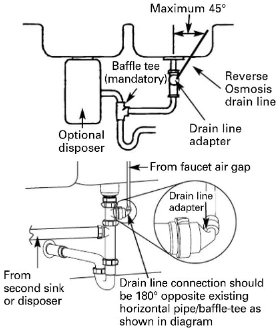
text_image
Maximum 45° Baffle tee (mandatory) Reverse Osmosis drain line Drain line adapter Optional disposer From faucet air gap Drain line adapter From second sink or disposer Drain line connection should be 180° opposite existing horizontal pipe/baffle-tee as shown in diagramProper drain line adapter orientation.
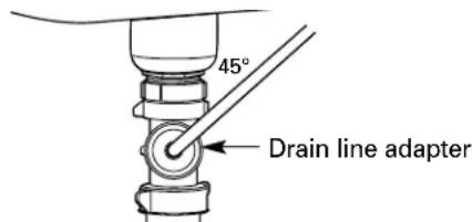
text_image
45° Drain line adapterSTORAGE TANK AND STARTUP
STORAGE TANK INSTALLATION
-
Remove the protective cap from the top of the tank.
-
Apply 2–3 wraps of thread tape, in a clockwise direction, to the tank threads.

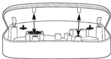
- Install the push-to-connect fittings on the threaded fitting on the tank as shown.
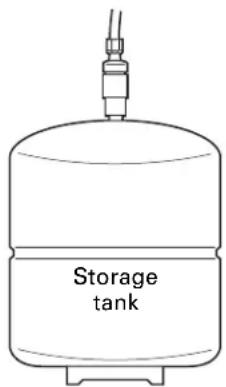
text_image
Storage tank- Push the 3/8" red banded tubing from the Reverse Osmosis System into the fitting on the storage tank.
SYSTEM STARTUP PROCEDURE
A CAUTION: If installing the unit in new construction, ensure that house plumbing is flushed thoroughly before opening the water supply valve.
- Check that all tubing connections are secure.
- Turn on the Feed Water Supply Valve.
- Check all connection points for leaks.
- Follow the Sanitization procedures on page 19.
- After sanitization is complete, reinstall prefilter, postfilter and Reverse Osmosis cartridges.
- Membrane contains a food grade preservative. Allow the system to fill the tank, then drain it completely four times before using the water from the system.
- Recheck all water connection points a few days later to check for small leaks.
Care and cleaning of the reverse osmosis system.
Prefilter, Postfilter and Reverse Osmosis Membrane Cartridge Replacement Procedure
When the amber filter light in the faucet base flashes, it is time to replace the prefilter and postfilter. This will occur every 6 months.
Be sure to wash your hands before handling inner parts of the system.
- Turn OFF the icemaker (if attached to the system).
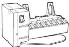
natural_image
Line drawing of a mechanical device with ports and connectors (no text or symbols)- Turn off water supply to the system.
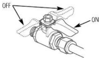
text_image
OFF ON-
Turn ON faucet to drain tank (may take several minutes). Turn OFF faucet when tank is empty.
-
Remove the prefilter, postfilter and Reverse Osmosis cartridge by rotating to the left about 1/3 turn.
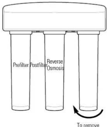
text_image
Prefilter Postfilter Reverse Osmosis To remove-
Follow Sanitizing the Reverse Osmosis System procedure found on page 19.
-
Remove foil on top of new replacement cartridges. Install new cartridges into the manifold by turning to the right about 1/3 turn until the alignment marks line up and the cartridges stop. DO NOT OVERTIGHTEN. The cartridges will rise up as they are turned.
NOTE: The prefilter and postfilter are identical. You may install either filter in the prefilter or postfilter position. The reverse osmosis cartridge is installed in the center position.
-
Turn ON water supply to fill the system (may take up to four hours). Check for leaks.
-
Remove the battery tray and replace the battery, positive "+" side down, to reset timer and monitor function in faucet base (see Battery Installation for proper procedure).
NOTE: Allow at least 90 seconds to elapse before installing new battery. This will ensure a full electronic reset and proper operation for the next 6 months.
-
If only the prefilter and postfilter are replaced, turn the faucet ON and empty the filled storage tank. If the membrane cartridge is replaced, fill and empty the storage tank a total of four times. (This will remove the food grade preservatives contained in new membranes. This preservative will give product water an unpleasant taste and odor.)
-
Once the storage tank is full, turn on the icemaker.

natural_image
Line drawing of a mechanical device with ports and wiring (no text or symbols)NOTE: System should be sanitized when replacing the prefilter and postfilter cartridge or the Reverse Osmosis cartridge. Follow the Sanitizing the Reverse Osmosis System procedure on page 19.
Sanitizing the Reverse Osmosis System
Sanitize upon installation of the Reverse Osmosis system and after servicing inner parts, including replacement of prefilter, postfilter and the membrane cartridge.
Be sure to wash your hands before handling inner parts of the system.
⚠️ CAUTION: Before sanitizing, be sure to remove all cartridges. Chlorine will destroy the Reverse Osmosis membrane cartridge.
- Follow steps 1 through 4 under Prefilter, Postfilter and Reverse Osmosis Membrane Cartridge Replacement Procedure.
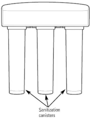
- Fill the empty canister labeled "Sanitization Canister" with water to within 1 inch of the upper opening. Add 1 oz. (2 Tbsp.) ordinary household bleach. Install canister into the prefilter canister position by turning to the right about 1/3 turn until the alignment marks line up and the canister stops.
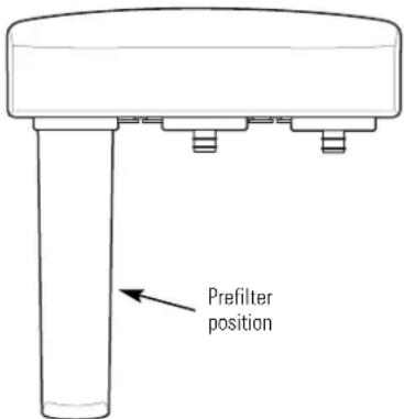
text_image
Prefilter position- Install the two additional "sanitization canisters" into the membrane canister and postfilter openings in the manifold by turning to the right about 1/3 turn until the alignment marks line up and the canister stops.
text_image
Sanitization canisters- Turn ON water supply. Turn ON faucet until water begins to flow from the faucet, then turn faucet OFF. Allow system to fill for 10 minutes.
- Turn faucet ON and allow water to flow for 20 minutes, or until bleach odor is gone. Turn OFF water supply again. Turn ON faucet to drain the system.
- Once the system is drained, turn the faucet OFF and remove the canisters by turning to the left about 1/3 turn. Keep these in a safe place until needed the next time.
Care and cleaning of the reverse osmosis system.
To obtain replacement filters, call toll-free GE Appliance Parts at 800.626.2002 (U.S.), 800.663.6060 (Canada–English), 800.361.3869 (Canada–French), or visit the store where you purchased your reverse osmosis system.
Prefilter/Postfilter Cartridge Replacement FQROPF Carbon Block
Reverse Osmosis Cartridge Replacement FQROMF Thin Film Polyamide
CAUTION: Before servicing the Reverse Osmosis system, close the water supply/saddle valve and open the RO water faucet. Allow the system to drain.
The Water Test Kit
To obtain an independent laboratory water test kit, please call Legend Technical Services at 1.800.949.8220, Option 4. They will contact you to find out what water tests you are interested in, and inform you of the cost of the testing. You will then receive a kit that will include all necessary tests to properly indicate the performance level of your system. Product water should be tested a minimum of every six months.
NOTE: When the TDS reduction of the system falls below 75%, it is time to replace the reverse osmosis cartridge in addition to the prefilter and postfilter.

Troubleshooting Tips
Save time and money! Review the charts on the following pages first and you may not need to call for service.
Problem Possible Causes What To Do
| Water has air bubbles and is cloudy | Air in system after installation. | • Will go away after it runs for a while. |
| Amber “FILTER” light on the faucet base of product water usage has faucet base. is flashing occurred. This is the maximum life of the prefilter and postfilter. | Six months or 900 gallons | • Replace the prefilter, postfilter and battery in the |
| Amber “RO” light flashing. NOTE: Disregard initial or regenerate the water supply.occasional short periods of this flashing light | Low usage of Reverse Osmosis product water. | • Open the RO water faucet and allow system to drain. Close the RO water faucet and allow the system to |
| The Reverse Osmosis cartridge is no longer removing the required amount of Total Dissolved Solids. | • Replace the Reverse Osmosis cartridge and flow control. | |
| Water supply to the Reverse Osmosis system not within specifications. | • Increase water pressure, precondition the water, etc., as needed to conform before doing maintenance on the Reverse Osmosis system. | |
| It takes 25 seconds or light flashes for RO light to switch to OK light with good filtered water. | • Normal operation. See description of operation on page 14. | |
| Indicator lights on faucet base not working | Faucet base leadwire not connected to the electronics board lead wire. | • Connect. |
| Battery installed incorrectly or expended. | • Observe orientation markings on page 14 and install correctly. Replace battery if old. | |
| Leadwires damaged. | • Inspect and repair as needed. | |
| Battery is dead. | • Use new CR2032, 3-volt battery. | |
| Amber “FILTER” light ON after filter and battery replacement | Electronics not fully reset when battery was replaced. | • Remove battery for 90 seconds, then reinstall. |
Before you call for service...

Troubleshooting Tips
Problem Possible Causes What To Do
| Chlorine taste and/or The ppm of chlorine in your odor in the Reverse Osmosis product water | water supply exceeds maximum limits and has destroyed the Reverse Osmosis membrane. maintenance on the Reverse Osmosis system. | ·If the water supply contains more than 2.0 ppm of chlorine, additional filtering of the water supply to the Reverse Osmosis is needed. Correct this condition before doing |
| The prefilter is no longer removing chlorine from flow control, screen, prefilter, postfilter and battery in the faucet base. | ·Replace the Reverse Osmosis membrane cartridge, | |
| Other taste and/or odor | High quality product water may have a different taste than what you're used to. | ·This is normal. |
| Low water usage. | ·Completely drain system and allow to refill. | |
| Contamination in product water storage. | ·Use sanitizing procedures. | |
| Prefilter and postfilter need to be changed. | ·Replace the prefilter and postfilter.·Sanitize system. | |
| Water leaking from faucet air gap hole | Drain side of faucet air gap (3/8" tubing) plugged, restricted or incorrectly connected to the drain. | ·Inspect and eliminate restriction or plug. It is important that there are no dips, loops or low spots in the drain line from the faucet air gap to the drain pipe. Refer to Installation Instructions for proper drain connection. If drain line adapter was used as the drain point, periodic inspection/cleaning is recommended. |
| System makes product water slowly | This is normal. | ·Water flow rate will be lower than your regular faucet.·It takes 3-4 hours to fill the tank. |
| Water supply to the Reverse Osmosis system not within specifications. | ·Increase water pressure, precondition the water, etc., as needed to conform before doing maintenance on the Reverse Osmosis system. | |
| Prefilter cartridge plugged with sediments. | ·Replace the prefilter. If rate does not increase, replace the postfilter. | |
| Reverse Osmosis membrane plugged with sediments. | ·Replace Reverse Osmosis membrane cartridge, flow control and battery in the faucet base. |
Common problems associated with filter or RO cartridge replacement.
ge.com

Troubleshooting Tips
Problem Possible Causes What To Do
| No Water | Water supply valve not turned on. | Turn water supply valve on. See diagram on page 11. |
| After filter change, tank is empty. water to fill the tank. | It takes 3–4 hours for RO system to provide enough | |
| Leaks at fittings | Improperly installed. | Reinstall. See Installation Instructions. |
| Sounds you may hear | Sink drain, drain water from system. | This is normal.Drain line can be installed to an alternative drain, such as a basement drain. See pages 15 and 16 for alternative drain configurations. |
| Faucet air gap—drain water flowing through the faucet system to reduce the pressure below 90 psi. This may be associated with high pressure water supply, generally 90 psi or greater. | Install a pressure regulator in the house water supply | |
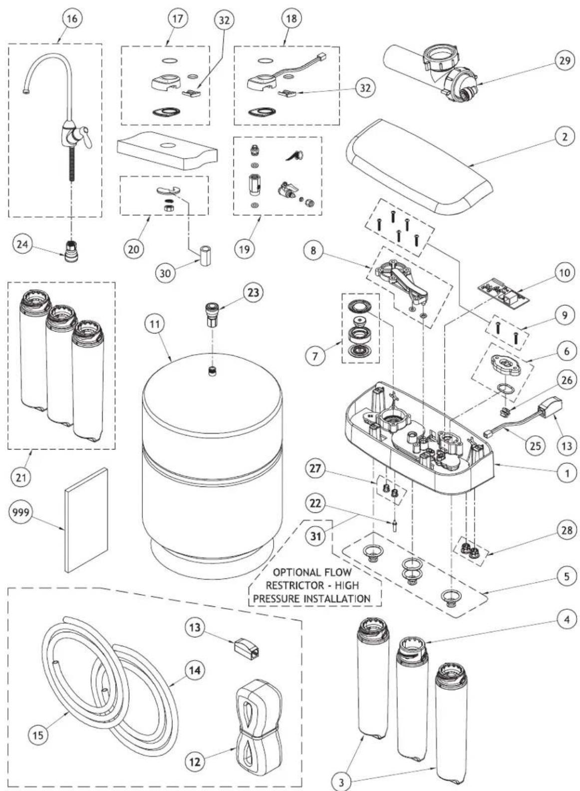
| An alternative flow restrictor for high pressure installations is available from GE (see item #31 on the parts list, page 25). Contact GE Parts and ask for Flow Restrictor, High Pressure, Part Number WS15X10049. |
PNRQ21LBN and PNRQ21LRB
text_image
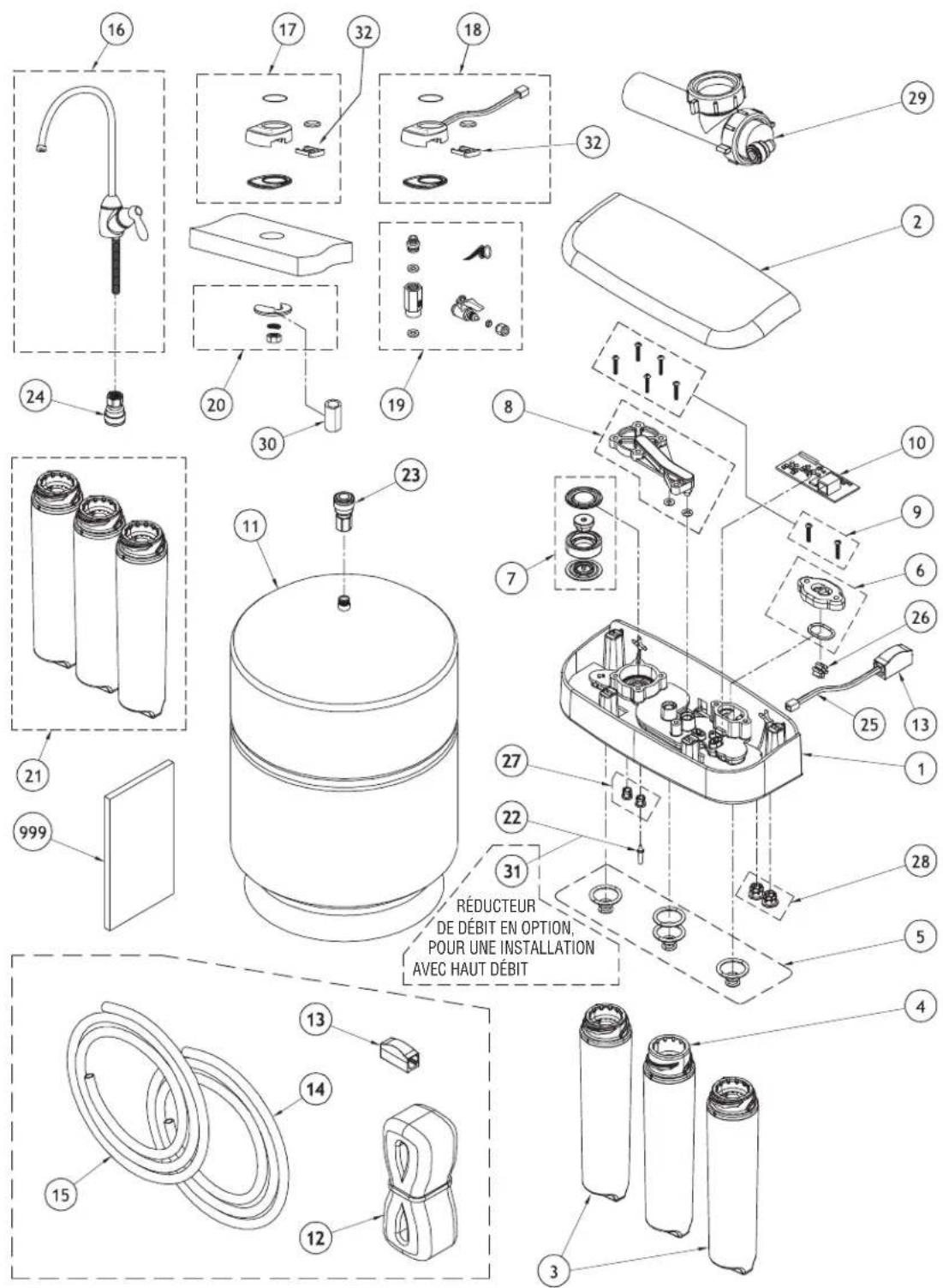
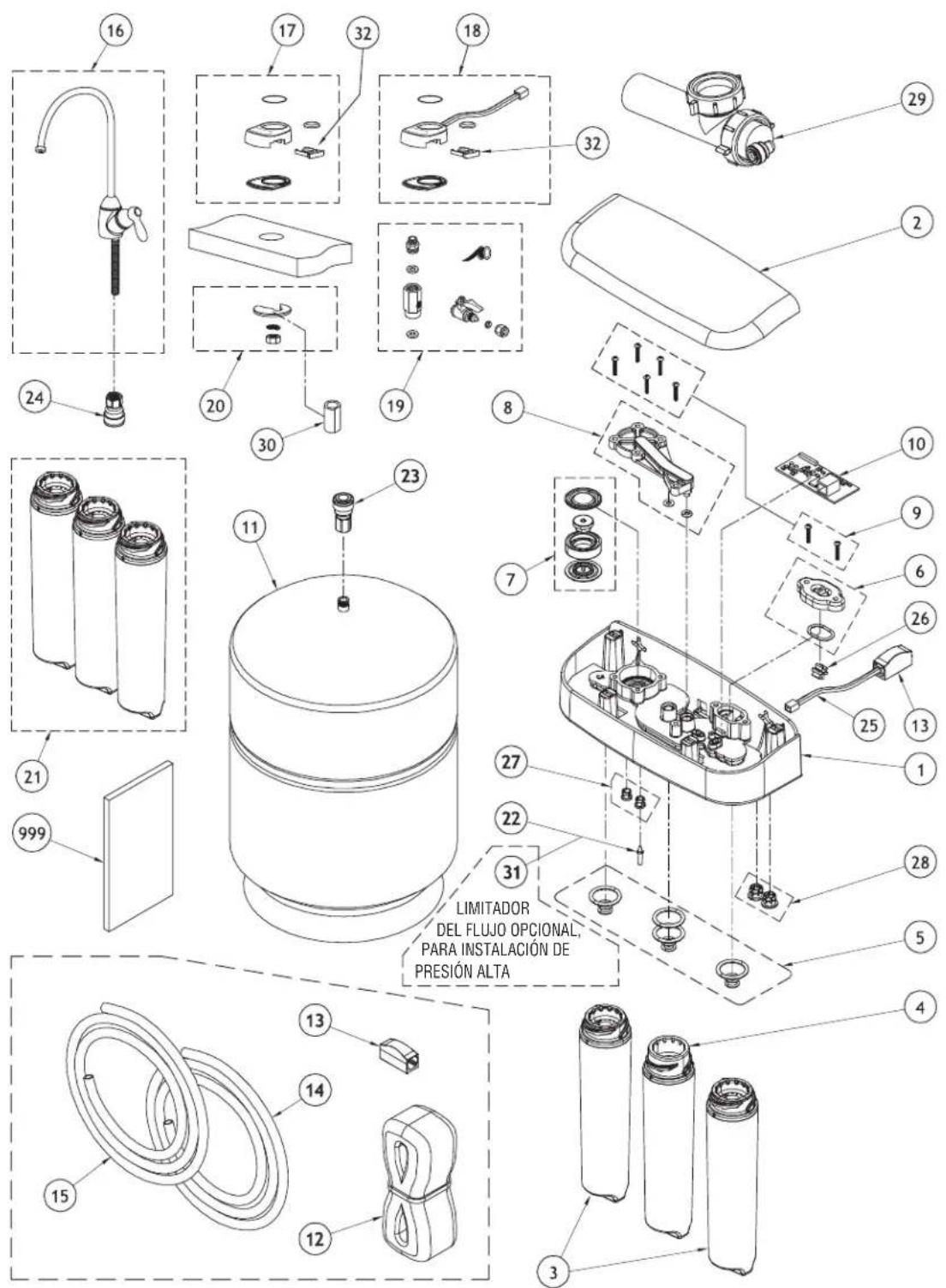
OPTIONAL FLOW RESTRICTOR - HIGH PRESSURE INSTALLATIONOPTIONAL PARTS FOR REMOTE INSTALLATION
| QTY | ||||
| P | P | |||
| N | N | |||
| R | R | |||
| Q | Q | |||
| 2 | 2 | |||
| 1 | 1 | |||
| L | L | |||
| B | R | |||
| REF. NO. GE PART NO. PART DESCRIPTION N B | ||||
| 0001 WS19X10022 MANIFOLD ASSEMBLY 1 1 | ||||
| 0002 WS19X10018 HOOD 1 1 | ||||
| 0003 FQROPF PRE AND POSTFILTER SET 1 1 | ||||
| 0004 FQROMF RO CARTRIDGE 1 1 | ||||
| 0005 WS03X10047 O-RING KIT (4 LG, 6 SM) | 1 1 | |||
| 0006 WS03X10048 FLOW METER CAP & O-RING | 1 | 1 | ||
| 0007 WS15X10040 SHUT-OFF VALVE ASSEMBLY | 1 1 | |||
| 0008 WS10X10030 SHUT-OFF COVER & CHECK | ||||
| BALL ASSEMBLY | 1 1 | |||
| 0009 WS02X10034 SCREWS, SET OF 7 | 1 1 | |||
| 0010 WS06X10005 CIRCUIT BOARD | 1 1 | |||
| 0011 WS32X10021 WATER STORAGE TANK | 1 1 | |||
| 0012 WS60X10009 6 PIN PHONE CORD—25 FT | -- | |||
| 0013 WS60X10010 PHONE CORD CONNECTOR | -- | |||
| 0014 WS07X10018 TUBING, 1/4" DIA. X 33'—WHITE | 1 | 1 | ||
| 0015 WS07X10019 TUBING, 3/8" DIA. X 33'—WHITE | 1 | 1 | ||
| 0016 WS15X10051 FAUCET, BRUSHED NICKEL, HIGH ARC | 1 - | |||
| WS15X10052 FAUCET, OIL-RUBBED BRONZE, HIGH ARC | - 1 | |||
| 0018 WS10X10036 FAUCET BASE, W/WIRE—BRUSHED NICKEL | 1 - | |||
| WS10X10037 FAUCET BASE, W/WIRE—OIL-RUBBED BRONZE | - 1 | |||
| 0019 WS18X10009 FEED WATER ADAPTER KIT | 1 | 1 | ||
| 0020 WS02X10031 WASHER & NUT—FAUCET | 1 1 | |||
| 0021 WS35X10041 SANITIZATION KIT | 1 1 | |||
| 0022 WS15X10041 FLOW RESTRICTOR | 1 1 | |||
| 0023 WS22X10055 TANK CONNECTOR, 3/8" TUBE | 1 | 1 | ||
| 0024 WS22X10054 FAUCET FITTING, 3/8" TUBE | 1 | 1 | ||
| 0025 WS19X10019 PHONE CORD JUMPER, 12" | 1 | 1 | ||
| 0026 WS19X10020 FLOW METER IMPELLER | 1 1 | |||
| 0027 WS22X10052 COLLET, 1/4" (SET OF 2) | 1 | 1 | ||
| 0028 WS22X10053 COLLET, 3/8" (SET OF 2) | 1 | 1 | ||
| 0029 WS18X10006 DRAIN LINE ADAPTER 1 1 | ||||
| 0030 WS02X10030 SPACER, FAUCET MOUNT | 1 1 | |||
| 0031 WS15X10049 FLOW RESTRICTOR, HIGH PRESSURE | - | - | ||
| 0032 WS21X10019 BATTERY TRAY | 1 | 1 | ||
| 0999 49-50214 OWNER'S MANUAL & INSTALLATION INSTRUCTIONS | 1 1 | |||
GE Reverse Osmosis System Warranty.

All warranty service provided by our SmartWater™ Authorized Servicer Network. To schedule service, call us toll-free at 800.GE.CARES (U.S.) or 866.777.7627 (Canada). Please have serial number and model number available when calling for service.
Staple your receipt here. Proof of the original purchase date is needed to obtain service under the warranty.
For The Period Of: GE Will Replace:
One Year
From the date of the
Any part of the Reverse Osmosis Filtration System which fails due to a defect in materials or workmanship. During this limited one-year warranty, GE will also provide, free of charge, all labored service to replace the defective part.
What GE Will Not Cover:
■Service trips to your home to teach you how to use the product.
■Improper installation, delivery or maintenance.
■Failure of the product if it is abused, misused, used for other than the intended purpose or used commercially.
■Use of this product where water is microbiologically unsafe or of unknown quality, without adequate disinfection. Systems certified for cyst reduction may be used on disinfected water that may contain filterable cysts.
■Filter cartridges, membrane cartridges and batteries after 30 days from date of purchase.
■Damage to the product caused by accident, fire, floods or acts of God.
■Incidental or consequential damage caused by possible defects with this appliance.
EXCLUSION OF IMPLIED WARRANTIES—Your sole and exclusive remedy is product repair as provided in this Limited Warranty. Any implied warranties, including the implied warranties of merchantability or fitness for a particular purpose, are limited to one year or the shortest period allowed by law.
This warranty is extended to the original purchaser and any succeeding owner for products purchased for home use within the USA. If the product is located in an area where service by a GE Authorized Servicer is not available, you may be responsible for a trip charge or you may be required to bring the product to an Authorized GE Service location for service. In Alaska, the warranty excludes the cost of shipping or service calls to your home.
Some states do not allow the exclusion or limitation of incidental or consequential damages. This warranty gives you specific legal rights, and you may also have other rights which vary from state to state. To know what your legal rights are, consult your local or state consumer affairs office or your state's Attorney General.
Warrantor: General Electric Company. Louisville, KY 40225
natural_image
Diagram of an open battery pack with three cylindrical batteries and a cable inserted into it, showing internal components and wiring (no text or symbols)natural_image
Line drawing of a standard kitchen faucet with handle and base (no text or symbols)natural_image
Diagram of three circular electronic components with arrows pointing to them, no text or symbols presenttext_image
Diagram showing three circular components with labeled connectors and directional arrows, likely illustrating a mechanical or electrical assembly.natural_image
Technical line drawing of a mechanical component with arrows indicating assembly or movement (no text or symbols)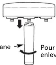
text_image
ane Pour enlevALIMENTATION D'EAU
natural_image
Line drawing of a faucet and sink with a curved pipe (no text or symbols)natural_image
Line drawing of a faucet and sink with a curved pipe (no text or symbols)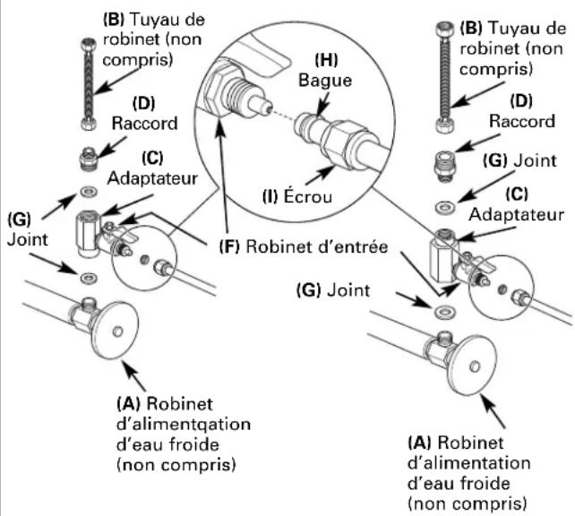
natural_image
Technical line drawing of a mechanical valve or fitting with a rotating knob (no text or symbols)text_image
Technical diagram showing a mechanical assembly with labeled parts 1 and 2, including a magnified inset view.natural_image
Illustration of two hands holding a pen with an arrow indicating direction (no text or symbols)natural_image
Illustration of two hands holding a tool with a small object inserted (no text or symbols)natural_image
Technical line drawing of a mechanical component with a magnified inset showing internal detail (no text or symbols)INSTALLATION DU ROBINET
MONTAGE DE ROBINET
natural_image
Line drawing of a hand holding a cable or wire (no text or symbols)natural_image
Simple line drawing of a pencil being inserted into a wire (no text or symbols)natural_image
Line drawing of a kitchen sink with faucet and appliance (no text or symbols)natural_image
Line drawing of a mechanical device with ports and wiring (no text or symbols)natural_image
Line drawing of a printer with ports and cables (no text or symbols)PNRQ21LBN, PNRQ21LRB
text_image
Exploded view diagram of a water purifier assembly with numbered parts and Chinese explanatory text.PIÈCES EN OPTION POUR UNE INSTALLATION À DISTANCE
| QUANTITÉ | ||
| P | P | |
| N | N | |
| R | R | |
| Q | Q | |
| 2 | 2 | |
| 1 | 1 | |
| L | L | |
| B | R | |
| N° DE RÉF N° DE PIÈCE DESCRIPTION DES PIÈCES | N | B |
| 0001 WS19X10022 ENSEMBLE DE COLLECTEUR 1 1 | |
| 0002 WS19X10018 CAPUCHON 1 1 | |
| 0003 FQROPF ENSEMBLE PRÉ-FILTRE ET POST-FILTRE 1 1 | |
| 0004 FQROMF CARTOUCHE D'OSMOSE INVERSÉE 1 1 | |
| 0005 WS03X10047 JEU DE JOINTS TORIQUES(4 GRANDS, 6 PETITS) 1 1 | |
| 0006 WS03X10048 CAPUCHON D'INDICATEUR DE DÉBITET JOINT TORIQUE 1 1 | |
| 0007 WS15X10040 ENSEMBLE DE ROBINET D'ARRÊT 1 1 | |
| 0008 WS10X10030 ENSEMBLE DE COUVERCLED'ARRÊT ET DE BALLE DE VÉRIFICATION | 1 1 |
| 0009 WS02X10034 VIS, ENSEMBLE DE 7 | 1 1 |
| 0010 WS06X10005 CARTE DE CIRCUIT IMPRIMÉ 1 1 | |
| 0011 WS32X10021 RÉSERVOIR DE STOCKAGE D'EAU | 1 1 |
| 0012 WS60X10009 CORDON TÉLÉPHONIQUE6 BROCHES—25 PIEDS | - - |
| 0013 WS60X10010 CONNECTEUR DE CORDONTÉLÉPHONIQUE | - - |
| 0014 WS07X10018 TUYAU, DIAMÈTRE DE 1/4 PO X33 PIEDS—BLANC | 1 1 |
| 0015 WS07X10019 TUYAU, DIAMÈTRE DE 3/8 PO X33 PIEDS—BLANC | 1 1 |
| 0016 WS15X10051 ROBINET, NICKEL BROSSE, ARC ÉLEVÉWS15X10052 ROBINET, BRONZE HUILÉ, ARC ÉLEVÉ | - 1 |
| 0018 WS10X10036 BASE DE ROBINET AVEC FIL—NICKEL BROSSEWS10X10037 BASE DE ROBINET AVEC FIL—BRONZE HUILÉ | - 1 |
| 0019 WS18X10009 TROUSSE D'ADAPTATEURD'ALIMENTATION D'EAU | 1 1 |
| 0020 WS02X10031 RONDELLIE ET ÉCROU—ROBINET | 1 1 |
| 0021 WS35X10041 TROUSSE D'ASEPTISATION | 1 1 |
| 0022 WS15X10041 RÉDUCTEUR DE DÉBIT | 1 1 |
| 0023 WS22X10055 RACCORD DE RÉSERVOIR, TUYAUDE 3/8 PO | 1 1 |
| 0024 WS22X10054 RACCORD DE ROBINET, TUYAU DE 3/8 PO | 1 1 |
| 0025 WS19X10019 CAVALIER DE CORDON TÉLÉPHONIQUE,12 PO | 1 1 |
| 0026 WS19X10020 IMPULSEUR D'INDICATEUR DE DÉBIT | 1 1 |
| 0027 WS22X10052 VIROLE, 1/4 PO (ENSEMBLE DE 2) | 1 1 |
| 0028 WS22X10053 VIROLE, 3/8 PO (ENSEMBLE DE 2) | 1 1 |
| 0029 WS18X10006 ADAPTATEUR DE TUYAU DE VIDANGE | 1 1 |
| 0030 WS02X10030 BAGUE DE MONTAGE DU ROBINET | 1 1 |
| 0031 WS15X10049 RÉDUCTEUR DE DÉBIT, HAUT DÉBIT | - - |
| 0032 WS21X10019 TIROIR À PILE | 1 1 |
| 0999 49-50214 MANUEL D'UTILISATIONET D'INSTALLATION | 1 1 |
Garant : General Electric Company. Louisville, KY 40225
natural_image
Diagram of an open battery pack with three cylindrical batteries and a cable inserted into it, showing internal components (no text or symbols)natural_image
Line drawing of a standard kitchen faucet with handle and base (no text or symbols)natural_image
Diagram of three electronic device ports with labeled connectors and connection points (no text or symbols)text_image
Diagram showing three circular components with labeled connectors and directional arrows pointing to them, likely illustrating a mechanical or electrical assembly.natural_image
Technical line drawing of a mechanical component with arrows indicating direction (no text or symbols)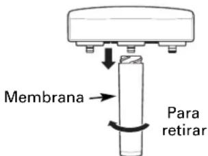
text_image
Membrana Para retirarnatural_image
Technical line drawing of a mechanical valve or fitting with a rotating knob (no text or symbols)text_image
Technical diagram showing a mechanical assembly with labeled parts 1 and 2, including a magnified inset view.natural_image
Illustration of two hands holding a tool with an arrow indicating direction (no text or symbols)natural_image
Illustration of two hands holding a pen or tool, no text or symbols presentnatural_image
Technical line drawing of a mechanical component with a magnified inset showing a detail (no text or symbols)ENSAMBLADURA DEL GRIFO
natural_image
Illustration of a hand holding a cable or wire (no text or symbols)natural_image
Illustration of a hand holding a cable or wire (no text or symbols visible)text_image
Technical diagram showing a pipe fitting with a circular component and dimension label '1''natural_image
Line drawing of a mechanical device with ports and wiring (no text or symbols)natural_image
Line drawing of a mechanical device with no visible text or symbolsPNRQ21LBN, PNRQ21LRB
Garante: General Electric Company. Louisville, KY 40225
General Manager, Customer Relations
GE Appliances, Appliance Park
Louisville, KY 40225
Registre su electrodoméstico ge.com
Have a question or need assistance with your appliance? Try the GE Appliances Website 24 hours a day, any day of the year! For greater convenience and faster service, you can now download Owner's Manuals or order parts on-line.
Schedule Service
In the U.S.: ge.com
Expert GE repair service is only one step away from your door. Schedule your service at your convenience by calling 800.GE.CARES (800.432.2737) during normal business hours.
In Canada, call 1.800.361.3400
Real Life Design Studio
In the U.S.: ge.com
GE supports the Universal Design concept—products, services and environments that can be used by people of all ages, sizes and capabilities. We recognize the need to design for a wide range of physical and mental abilities and impairments. For details of GE's Universal Design applications, including kitchen design ideas for people with disabilities, check out our Website today. For the hearing impaired, please call 800.TDD.GEAC (800.833.4322).
In Canada, contact: Manager, Consumer Relations, Camco, Inc.
Suite 310, 1 Factory Lane
Moncton, N.B. E1C 9M3
Extended Warranties
In the U.S.: ge.com
Purchase a GE extended warranty and learn about special discounts that are available while your warranty is still in effect. You can purchase it on-line anytime, or call 800.626.2224 during normal business hours. GE Consumer Home Services will still be there after your warranty expires. In Canada, call 1.888.261.2133
Parts and Accessories
In the U.S.: ge.com
Individuals qualified to service their own appliances can have parts or accessories sent directly to their homes (VISA, MasterCard and Discover cards are accepted). Order on-line today, 24 hours every day or by phone at 800.626.2002 during normal business hours.
Instructions contained in this manual cover procedures to be performed by any user. Other servicing generally should be referred to qualified service personnel. Caution must be exercised, since improper servicing may cause unsafe operation.
Customers in Canada should consult the yellow pages for the nearest Camco service center, or call 1.888.261.3055.

Contact Us
In the U.S.: ge.com
If you are not satisfied with the service you receive from GE, contact us on our Website with all the details including your phone number, or write to: General Manager, Customer Relations
GE Appliances, Appliance Park
Louisville, KY 40225
In Canada: www.geappliances.ca, or write to: Director, Consumer Relations, Camco, Inc.
Suite 310, 1 Factory Lane
Moncton, N.B. E1C 9M3
Register Your Appliance
In the U.S.: ge.com
Register your new appliance on-line—at your convenience! Timely product registration will allow for enhanced communication and prompt service under the terms of your warranty, should the need arise. You may also mail in the pre-printed registration card included in the packing material, or detach and use the form in this Owner's
Manual. In Canada: www.geappliances.ca